

Page 1

MODEL 220
HYDRAULIC
IMPACT HAMMER
OPERATING AND MAINTENANCE MANUAL
J&M MODEL 220
SERIAL NUMBERS: 484002 AND ABOVE
OM-220-325-0296
HYDRAULIC IMPACT HAMMER
WITH MODEL 335 POWER PACK
J&M FOUNDATION
EQUIPMENT, LLC
SPECIALIZING IN PILE DRIVING EQUIPMENT
Page 2

MODEL 220
HYDRAULIC
IMPACT HAMMER
Page 3

MODEL 220
HYDRAULIC
IMPACT HAMMER
This manual was prepared to acquaint the owner, operator and serviceman with the
construction, operation and servicing of the J&M Model 220 Hydraulic Impact Pile Hammer
and the J&M Model 325 Power Unit. We strongly suggest that this manual be studied carefully
and understood by all personnel involved in operating or performing maintenance work on the
hammer. J&M equipment is engineered to provide reliable operation and a long servJ&M life
under normal operating conditions. Equipment reliability and service life can be improved by
following the maintenance procedures in this manual.
This manual is divided into seven sections- Introduction, General information, Preparation for
Operation, Operation, Maintenance, Trouble-Shooting and Ordering Parts.
The General Information section contains a brief description of the hammer and specification
information.
The Preparation for Operation section contains information about maintenance and other work
required before starting the hammer.
The Operation section includes general operating information plus details on hot and cold
weather operation.
The Maintenance & Adjustments section contains routine maintenance procedures and
instructions for making adjustments and repairs to the hammer.
The Trouble-Shooting section has suggestions for identifying and resolving operating
difficulties.
The Ordering Parts section contains information for ordering parts including parts drawings and
lists.
PREFACE
Page 4

MODEL 220
HYDRAULIC
IMPACT HAMMER
Page 5

MODEL 220
HYDRAULIC
IMPACT HAMMER
J&M, Foundation Equipment, LLC. (J&M) warrants new products sold by it to be free from
defects in material and workmanship for a period of 90 days after date of delivery to the first
user and subject to the following conditions: J&M’s obligation and liability under this warranty is
expressly limited to repairing or replacing, at J&M's option, any parts which appear to J&M
upon inspection to have been defective in material or workmanship. Such parts shall be
provided at no cost to the user at the business establishment of J&M or at the J&M distributor
of the product during regular working hours.
This warranty shall not apply to component parts or accessories of products not manufactured
by J&M and which carry the warranty of the manufacturer thereof or to normal maintenance
parts (such as filters).
Replacement or repair parts installed in the product covered by this warranty are warranted
only for the remainder of the warranty as if such parts were original components of said
product.
J&M's obligation under this warranty shall not include any transportation charges, costs of
installation, duty, taxes or any other charges whatsoever, or any liability for direct, indirect,
incidental, or consequential damage or delay.
If requested by J&M, products or parts for which a warranty claim is made are to be returned
transportation prepaid to J&M.
Any improper use, including operation after discovery of defective or worn parts, operation
beyond rated capacity, substitution of parts not approved by J&M or any alteration or repair by
others in such manner as is J&M's judgment affects the product materially and adversely shall
void the warranty.
For impact pile hammers, driving in excess of 10 blows per inch (set of 0.1 inch per blow) is
considered practical refusal. Driving in excess of 10 blows per inch for more than 6 inches of
driving or driving in excess of 20 blows per inch at all is considered improper use and will void
the hammer warranty.
For vibratory drivers, driving when penetration is less than 1" per minute is considered practical
refusal. Driving when penetration is less than 1" per minute for more then 5 minutes of driving
or driving at all when penetration is less than 1" per minute and amplitude is greater than
1" (vibrator and pile are bouncing) is considered improper use and will void the vibrator
warranty.
J&M makes no other warranty, expressed or implied, and makes no warranty of
merchantability or fitness for any particular purpose.
No employee or representative is authorized to change this warranty unless such change is
made in writing and signed by an officer of J&M.
J&M, LLC.
STANDARD WARRANTY
Page 6

MODEL 220
HYDRAULIC
IMPACT HAMMER
I. GENERAL INFORMATION
A. General Description I-1
B. Major Components (line drawing) I-1
C. Specifications I-5
II. PREPARATION FOR OPERATION
A. General II-1
B. Safety Precautions II-1
C. Handling II-4
D. Connecting Crane Line To Hammer II-5
E. Attachment Of Lead Guides II-6
F. Attachment Of Drive Cap II-6
G. Mounting Hammer In Lead II-7
H. Connection Of Hydraulic Hoses II-8
I. Filling The Hammer Pressure Hose II-9
J. Filling Variable Stroke Cylinder Hoses II-10
K. Setting Variable Stroke Cylinder Pressure II-10
L. Fuel, Lubricating Oil And Grease II-11
III. OPERATING INSTRUCTIONS
A. Completion of Set-up and Maintenance III-2
B. Control Panel III-2
C. Starting And Warming Up The Engine III-3
D. Warming Hydraulic Oil III-3
E. Operation Of The Hammer III-4
1. Rated Hammer Energy III-4
2. Maximum blows per inch III-4
3. Stroke Control III-4
4. Stroke Setting III-5
F. Starting The Hammer III-6
G. Stopping The Hammer III-6
H. Single Blow Operation III-6
I. Emergency Stop III-6
J. Engine Shut Down III-6
K. Hot & Cold Weather Operation III-7
IV. MAINTENANCE AND ADJUSTMENTS
A. General IV-1
B. Maintenance - Daily IV-2
C. After Start-Up, Check The Following IV-3
D. Maintenance -Monthly IV-3
TABLE OF CONTENTS
PAGE
Page 7

MODEL 220
HYDRAULIC
IMPACT HAMMER
TABLE OF CONTENTS
IV. MAINTENANCE AND ADJUSTMENTS (CONTINUED)
E. Maintenance - Every 4 Months IV-3
F. Annually IV-3
G. Severe Conditions IV-4
H. Lubrication IV-4
I. Hydraulic Oil IV-5
J. Capacities IV-7
K. Draining And Filling Hydraulic Reservoir IV-7
L. Changing The Hydraulic Return Filter Element IV-8
M. Setting Main Relief Valve IV-9
N. Setting Stroke Control (Clamp) Reli ef Valve IV-10
O. Tensioning Wire Ropes IV-10
P. Charging Accumulators IV-12
Q. Replacing Ram Connection IV-13
R. Bolt Torque Information IV-14
S. Checking & Replacing Recoil Dampener IV-15
T. Checking & Replacing Cushion Material IV-15
V. HYDRAULIC CIRCUITRY
A. Drive Pump V-1
B. Stroke Control Pump V-2
C. Other V-3
Hydraulic Schematic V-4
D. Hydraulic Components List V-5
VI. ELECTRICAL CIRCUITRY
A. Diesel Engine VI-1
B. Stroke Range Select VI-2
C. Hydraulic Hammer VI-2
D. Remote - Local Control VI-2
E. Engine Throttle VI-3
F. Tachometer VI-3
G. Other VI-3
Electrical Layout VI-4
Electrical Schematic VI-5
H. Electrical Components List VI-6
PAGE
Page 8

MODEL 220
HYDRAULIC
IMPACT HAMMER
TABLE OF CONTENTS
VII. GENERAL DATA
A. Abbreviations VII-1
B. Screws And Bolts VII-2
C. Serial Number Locations VII-2
VIII. ORDERING PARTS
A. Procedure VIII-1
B. Fitting Description Key VIII-2
Fitting Description Selector Chart - SC1 VIII-3
C. Hose Description Code VIII-4
D. Parts Identification VIII-5
E. Miscellaneous Accessories VIII-48
F. Recommended Spare Parts VIII-51
G. Recommended Tightening Torque VIII-52
Page 9

MODEL 220
HYDRAULIC
IMPACT HAMMER
I. GENERAL INFORMATION
A. GENERAL DESCRIPTION
The J&M Model 220 Hydraulic Hammer is a Free-Fall hammer. The ram is lifted by
the hydraulic actuator and then allowed to free-fall, impacting the pile. The hammer
has been designed to provide maximum flexibility by enabling the contractor to vary
the energy range of the hammer to suit job conditions. The 220 hammer design
incorporates an all hydraulic control system, with no electrical or electronic controls
used, to ensure reliability and field serviceability. Further, without the need for
vulnerable umbilical cords, this unit is readily adaptable to alternate hydraulic power
sources.
The 220 hammer is normally powered by the same Model 175 power unit that
powers J&M Vibratory Hammers and J&M Earth Augers. This permits the
contractor to use a single power unit on jobs where both the Impact Hammer and a
Vibratory Hammer or Auger are needed. The Hammer can also be powered by any
source providing the required flow, pressure, cooling and filtration. The 220
Hydraulic Hammer delivers 46,000 ft-lbs (6359.7 Kg-M) of energy at its full stroke of
4’-0” (1.2M) at a blow rate of 40 blows per minute.
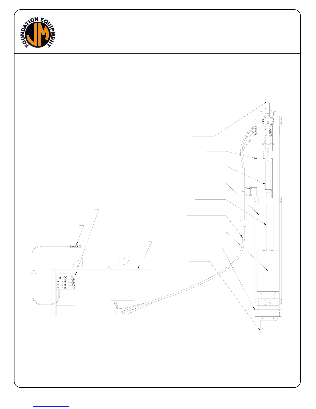
B. MAJOR COMPONENTS
The hammer system consists of 8 major components (Fig. 1) page I-4:
Hydraulic Actuator
Ram
Guide Structure
Lifting Bale
Drive Cap
Controls
Interconnecting Hoses
Power Unit
Hydraulic Actuator
The hammer is driven by the hydraulic actuator. The actuator is coupled to the ram
using a shock absorbing, self aligning, connection. Hydraulic oil flows from the
power unit, at pressure, to the actuator which accelerates the ram upward.
Attached to the ram is a trip bar which activates a trip valve after the ram has risen
a predetermined distance. Activation of the trip valve stops the flow of oil to the
actuator. The ram then decelerates and free falls to impact the pile. Power unit
energy is stored in a hydraulic accumulator while the ram is falling.
I-1
Page 10

MODEL 220
HYDRAULIC
IMPACT HAMMER
I. GENERAL INFORMATION
B. MAJOR COMPONENTS (CONTINUED)
Ram
The ram is a one piece high strength steel forging. The one piece construction of
the ram eliminates slack in the driving system and provides maximum energy
transfer to the pile. The one piece construction also eliminates the dangers of
structural failure known to exist in rams constructed of separate segments. High
performance, non-metallic, bearings, retained within the ram, prevent guide column
wear and reduces maintenance and lubrication requirements. The shock and
vibration, generated when the ram impacts the pile, are isolated from the hydraulic
actuator by an elastomeric, self aligning, coupling.
Guide Structure
The guide structure consists of tubular steel guide columns and connection plates.
The guide columns serve to guide the ram and provide the rigidity required to allow
the driving of batter piles. Guide columns, connecting plates and lifting bale are
held together by tensioned wire ropes which run from the base plate to the top of
the lifting bale. These cables provide a resilient means of connection and eliminate
the need for keys or bolted connections. The hammer is designed to fit in 26” x 8”
rail leads produced by J&M and other manufacturers. The connecting plates
provide mounting points for the lead guide rails necessary for J&M leads and
various other hammer guidance systems.
Lifting Bale
The lifting bale surrounds and protects the hydraulic actuator and hoses from
damage and is the attachment point for the lifting sheave. Two energy storing
hydraulic accumulators are mounted to, and protected by, the lifting bale.
Incorporated in the lifting bale design are the connection flanges for the hydraulic
supply hoses, and a shock absorbing hose support.
Drive Cap Assembly
Striking energy of the ram is transmitted to the pile through the three elements of the
drive cap assembly. The ram impacts the forged steel striker block which self aligns
and self centers within the lower connecting plate. Ram energy is transferred
through cushion material into the DCB-X drive cap base. The DCB-X serves to
retain the cushion material, Guide the piling, and adapt to various styles of J&M
piling inserts. Piling inserts adapt the hammer to most popular types of piling and
retain additional cushion material when required.
I-2
Page 11

MODEL 220
HYDRAULIC
IMPACT HAMMER
I. GENERAL INFORMATION
B. MAJOR COMPONENTS (CONTINUED)
Controls
The hammer is controlled by a remote electric/hydraulic system in the power unit
which allows for both manual single blow operation or automatic continuous stroke
operation. The stroke of the ram can be varied between 12” (.3M) and 48” (1.2M),
on-the-fly, allowing control of the hammer energy to suit various types of piling and
soil conditions. Under continuous operation, the hammer will operate at 45 blows
per minute at the maximum energy setting. The blow rate will increase at lower
energy settings. Control of the continuous cycling of the hammer is fully hydraulic
(non-electric), operated by valves contained within the actuator assembly. No
maintenance of adjustment of these valves is normally required. The hammer can
be operated from the control panel at the power unit, the remote pendant control or
the radio remote control unit
Interconnecting Hoses
Hydraulic power is transmitted from the power unit to the hammer through 100 ft.
(30M) of steel braid reinforced hydraulic hoses (4). High pressure, threaded type,
quick disconnects on these hoses facilitate connection to the power unit without oil
loss. Dust covers are provided to keep disconnects clean when the hammer is
disconnected.
Power Unit
Power for the hammer is normally provided by a free-standing, Model 325, dieselhydraulic power unit. The Model 325 is powered by a Caterpillar 3306 engine which
develops 325 Hp at 2100 rpm. The totally enclosed power unit is mounted on a skid
type fuel tank sub-base, and has lockable doors. Central lifting of the power unit is
facilitated by an integral lifting bale. A control panel at the side of the unit contains
all the operating gages and controls. A common reservoir supplies hydraulic oil to
the main pump and the stroke control pump. Filtration and cooling means for the
hydraulic oil are incorporated within the power unit. Electro/hydraulic valves are
provided for hammer start/stop and stroke control. Pressure limiting valves are
included for all systems. Four hydraulic hoses connect the power unit to the Model
220 hammer. This power unit can also be crane mounted for ease of operation.
If the crane is capable of providing the required flow, pressure, cooling and filtration
to the hammer, it is possible to adapt it for hammer operation and eliminate the
power unit
I-3
Page 12
MODEL 220
HYDRAULIC
IMPACT HAMMER
I. GENERAL INFORMATION
B. MAJOR COMPONENTS (CONTINUED)
SHEAVE
LIFTING BALE
HYD ACTUATOR ASM
CONTROL PANEL
CONTROL PENDANT
175 POWER UNIT
GUIDE STRUCTURE
TRIP BAR
HOSES
RAM
DRIVE CAP
INSERT
FIG 1
I-4
Page 13

MODEL 220
HYDRAULIC
IMPACT HAMMER
I. GENERAL INFORMATION
C. SPECIFICATIONS
Working Specifications
Designation J&M Model 220
Maximum stroke 4'-0" (1.2 Meter)
Rated energy @ maximum stroke 88,000 ft-lbs (119kj)
Blow rate @ maximum stroke 45 bpm
Minimum stroke 1' (0.3 Meter)
Rated energy @ minimum stroke 11,500 ft-lbs (15 kN-m)
Blow rate @ minimum stroke 75 bpm
Weights and Dimensions
Ram weight 22,000 lbs (5,215 kg)
Hammer weight (bare)* 35,000 lbs (8,573 kg)*
Complete operating weight with cap*,** 41395 lbs (18776 kg)**
Length (bare)** 121-0" (6401mm)
Complete operating length with cap** 23'-7” (7188mm)**
Width (without guides) 32" (660 mm)
Depth 48" (1219mm)
Depth centerline to back 18" (457 mm)
Depth centerline to front 18" (457 mm)
Hydraulic hose length (standard) 150' (45 m)
*Weight includes one half of hydraulic hoses.
**Set up for 26" leads and 14" square concrete pile.
Power Unit
Designation J&M Model 325
Engine CAT 3306TA
Max. power 335 HP (250kW)
Operating speed 2100 rpm
Max. drive pressure 5,000 psi (345 bar)
Drive flow 87 gpm (330 lpm)
Stroke control pressure 4,300 psi (295 bar)
Stroke control flow 5.2 gpm (20 lpm)
Weight 9,600 lbs (4355 kg)*
Length 126" (320 cm)
Width 60" (152 cm)
Height 75.5" (192 cm)
I-5
Page 14

MODEL 220
HYDRAULIC
IMPACT HAMMER
II. PREPARATION FOR OPERATION
A. GENERAL
When loading and unpacking the hydraulic hammer and accessories, use extreme
care. For your protection, make a thorough inspection of the unit immediately on
delivery. In case of any damage or shortage, notify the transit agent at once and
have the delivering carrier make a notation on the freight bill. Use timber, heavy
duty banding, etc to block ram movement during shipment.
(SEE SECTION II C FOR LIFTING INSTRUCTIONS)
B. SAFETY PRECAUTIONS
Safety is basically a matter of common sense. There are standard safety rules, but
each situation has its own peculiarities which can not always be covered by rules.
Therefore, your experience and common sense will be your best guide to safety.
Be ever watchful for safety hazards and correct deficiencies promptly.
Use the following safety precautions as a general guide to safe operations:
1. Read the manual thoroughly before operating or working on the equipment.
2. Read and follow any safety instructions in the CATERPILLAR engine operators
manual.
3. Only well trained and experienced personnel should attempt to operate or maintain
this equipment.
4. Never adjust, lubricate or repair the unit when it is in operation, or lifted above
ground level.
5. Never remove, paint over or cover warning or safety labels. If labels become
damaged or unreadable, replace immediately.
6. All personnel should wear approved safety clothing, including HARD HATS,
SAFETY SHOES, SAFETY GLASSES and HEARING PROTECTION when in the
vicinity of this machinery.
7. Do not stand any closer to this equipment than necessary when it is in operation.
Parts may loosen and fall. Piling may shatter or break. Never stand under
operating, or elevated, equipment.
8. When maintaining or repairing the equipment, never substitute parts not supplied,
or approved in writing, by J&M.
9. Do not weld, or flame cut, on this equipment.
10. Never use or store flammable liquids on or near the engine.
11. Insure that all lifting equipment, including cranes, wire rope, slings, hooks, shackles,
etc., are properly sized for the worst case loads anticipated during operations.
12. If there are any questions about the weights, specifications, or performance of the
unit, contact J&M before handling or operating the equipment.
13. If the equipment is to be used for anything other than driving plumb piles, contact
J&M before using the unit.
14. Check wire rope clips for tightness, and check wire ropes for wear, daily.
15. Insure that ground vibrations will not damage or collapse adjacent structures or
excavations.
II-1
Page 15

MODEL 220
HYDRAULIC
IMPACT HAMMER
II. PREPARATION FOR OPERATION
B. SAFETY PRECAUTIONS (CONTINUED)
16. Remove all tools, parts and electrical cords before starting the unit.
17. When operating in an enclosed area, pipe exhaust fumes outside. Continued
breathing of exhaust fumes may be fatal.
18. When servicing batteries, do not smoke or use open flames in the vicinity. Batteries
generate explosive gas during charging. There must be proper ventilation when
charging batteries.
19. When filling fuel tank, do not smoke or use open flame in the vicinity.
20. If abnormal equipment operation is observed, discontinue use immediately and
correct the problem. Do not leave the equipment control pendant (radio control)
unattended.
21. Store oily rags in approved containers, and away from engine exhaust system.
22. Make sure that the hammer is OFF before starting the power unit engine.
23. Do not adjust, or set, hydraulic pressures higher or lower than those specified in the
manual.
24. Never operate this equipment with hydraulic hoses that are damaged or “kinked”.
Replace damaged hoses immediately.
25. Do not lift, or support, hydraulic hoses with wire rope slings.
26. Never attempt to connect quick disconnects when the power unit is running.
27. Do not pull on, or attempt to move equipment, with hydraulic hoses.
28. Do not attempt to locate hydraulic leaks with your hands. High pressure hydraulic
leaks can penetrate the skin, causing severe damage, blood poisoning and
infection. Do not attempt to repair leaks while the equipment is in operation.
29. Do not attempt to tighten, or loosen, fittings or hoses when the machine is in
operation.
30. Power unit must always be placed on level, stable, ground.
31. Do not remove power unit heat shields, or operate power unit without heat shields.
Severe fires may result.
32. A properly maintained fire extinguisher, suitable for oil fires, must be kept in the
immediate vicinity of equipment operations.
33. When moving or transporting this equipment, insure that the vehicle or vessel is of
sufficient capacity to handle the load, and that the equipment is properly tied down.
34. Always block the ram, to prevent movement during transport.
35. When moving or transporting this equipment, be sure that quick disconnect dust
caps are tight, and that cap safety cables are in place. Be sure that all equipment
parts are tight, or properly secured, before shipment. Unsecured parts may vibrate
loose and fall, during transport, causing injury or property damage.
36. Keep crane boom, piles, leads, wire rope and other equipment at least 15’ (5M)
from electrical power lines, transformers and other electrical equipment, or at such
distance as required by applicable safety codes.
II-2
Page 16

MODEL 220
HYDRAULIC
IMPACT HAMMER
II. PREPARATION FOR OPERATION
B. SAFETY PRECAUTIONS (CONTINUED)
37. Rounded or damaged bolt heads or nuts should be replaced so that proper torque
values may be obtained. Proper torque values are necessary to prevent parts on
this equipment, leads and crane boom from loosening and falling. Refer to Torque
Chart, in the manual, for proper values.
38. Always be sure that the crane line is aligned with the centerline of the pile. Do not
side load crane boom or hammer. Dangerous crane boom, or hammer, damage
may result.
39. Use tag line to control hammer whenever possible.
40. When driving “batter” piles, insure that the leads, and crane boom, have sufficient
bending strength to handle the worst case load. Consult J&M.
41. Do not attempt to service hydraulic accumulators without first venting all high
pressure gas from these units.
42. Pre-charge accumulators only to pressures specified, and only with Nitrogen gas.
43. Pile ends must be cut square, and flat, before cushion material and/or drive cap are
placed onto pile.
44. Use only pile caps that are correctly sized for the type, cushion material and pile
size being driven.
45. Before starting driving operations, check that the hammer, striker block and pile cap
are properly aligned with the centerline of the pile. Dangerous lateral forces,
generated by misalignment, may damage hammer or break piling, with resultant
hazard from falling objects.
46. Stay well clear of ram point, pile cap and striker block. Fragments of metal may be
broken, or spalled off, and ejected at high speed.
47. Large amounts of heat are generated, within cushion material, during driving.
Cushion material, or flammable materials in the vicinity, may ignite. Personnel
should use extreme caution, and avoid contact with ram point, cushion material and
drive cap.
48. It is the responsibility of the contractor to determine what, if any, hazardous
materials, or gases, may be emitted from cushion materials due to deterioration,
decomposition, excessive temperature or combustion. Contact the cushion
material manufacturer.
49. Frequently inspect and tighten the wire ropes, wire rope clips and pins that secure
the drive cap to the hammer. Replace these components at the first sign of wear or
fatigue. Tighten clips regularly.
REMEMBER, SAFETY IS EVERYONE’S BUSINESS.
II-3
Page 17
MODEL 220
HYDRAULIC
IMPACT HAMMER
II. PREPARATION FOR OPERATION
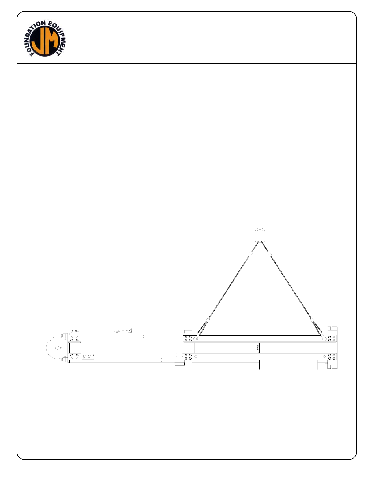
C. HANDLING
Safe handling practices will insure protection of both the hammer and personnel
working near the unit. Do not pick up the hammer by the guide columns. Doing so
can scratch the surface finish on the columns and damage the ram bearings.
To lift hammer horizontally (See Fig 1):
The hammer is designed to be picked up by the lead guide rails. Use shackles at
each of the four lifting holes provided in the lead guides to attach the four lifting
cables. Alternately, the hammer can be picked up using the lifting sheave and a pin
through the cable ears in the bottom plate. Ensure that the lifting cables are
properly sized for the hammer weight and sling angle.
Always block the ram, to prevent movement during transport and / or lifting.
FIG 1
II-4
Page 18
MODEL 220
HYDRAULIC
IMPACT HAMMER
II. PREPARATION FOR OPERATION
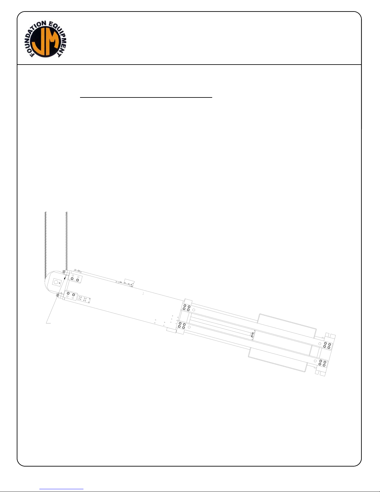
D. CONNECTING CRANE LINE TO HAMMER
Connect the crane line directly to the hammer using the lifting sheave. The
hammer is designed to be used with a two-part line. If a single-part line is desired,
the sheave can be replaced with a sleeve p/n 160777.
To lift the hammer to a vertical position, first remove the rope guide bolt and sleeve.
(See Fig 2) Pass the crane wire rope around the lifting sheave and re-attach to
crane boom. Lift hammer to the vertical position. Re-install rope guide bolt and
sleeve.
TEMPORARILY REMOVE ROPE
GUIDE BOLT AND SLEEVE
FIG 2
II-5
Page 19

MODEL 220
HYDRAULIC
IMPACT HAMMER
II. PREPARATION FOR OPERATION
E. ATTACHMENT OF LEAD GUIDES
The hammer is usually shipped with lead or spud guides already in place. If they
are not attached, bolt them into place at the sides of the hammer using the twenty
bolt holes provided on each side of the hammer.
With fixed leads, it is sometimes convenient to stand the hammer in the leads prior
to attachment of the back lead guides.
The lead guide attachment bolts should be properly torqued, using the lock washers
provided, to prevent their coming loose. Torque 1.25-7UNC SHCS to 1,600 Ft-lbs
(221.1 Kg-M).
Do not weld on hammer.
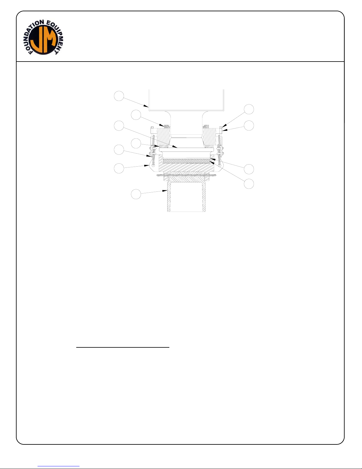
F. ATTACHMENT OF DRIVE CAP (See Fig. 3)
To attach drive cap: Set drive cap insert [11] on dunnage or firm ground. Set drive
cap base [4] (DCB-2 for 32" leads) onto drive cap insert. Attach with wire rope
through two holes provided.
Place 2"(50mm) thick and 22 1/2”(571mm) diameter cushion material [8] into top of
DCB-1 drive cap base (2”(50mm) thick and 25”(635mm) diameter for DCB-2 drive
cap base). Place 1/2”(13mm) thick aluminum plate [7] on top of cushion material.
This plate holds the cushion material in place if it fractures during driving.
Place the 9 1/2” (243mm) thick tapered steel striker block [3] on top of the
aluminum plate
Place the recoil dampener [9] around the top of the striker block.
Set the hammer onto the assembled drive cap set-up. The tapered striker block fits
inside the bottom of the hammer and will lift the ram [1] as the hammer is lowered
onto it. The hammer base plate [2] should sit squarely on the recoil dampener.
Attach the drive cap to the hammer with 3/4”(19mm) wire rope [10]. Insert bolt [6]
through the holes in the cable ears on hammer base plate [2] to keep the
3/4”(19mm) wire rope [10] in place. Secure bolt [6] with the locking nut provided
and fully tighten. Provide enough slack in the wire rope so that, when the hammer
is lifted, 1”-2” (25-50mm) of space should exist between the bottom of the hammer
and the recoil dampener.
II-6
Page 20
MODEL 220
HYDRAULIC
IMPACT HAMMER
II. PREPARATION FOR OPERATION
1
3
10
4
32” LEADS
1 Ram SAME
2 Hammer Base Plate SAME
3 Striker Block SAME
4 Drive Cap Base 700006
5 Bumper SAME
6 Bolt & Nut SAME
7 Alluminum Plate 700004
8 Cushion 700002
9 Recoil Dampener SAME
10 3/4" Wire Rope
11 Drive Cap Insert
G. MOUNTING HAMMER IN LEAD
To slide the hammer into swinging leads, in horizontal position, pick up hammer as
described in Section II-C.
For vertical installation into leads, first attach the crane line to the hammer as
described in Section II-D. and lift hammer carefully into vertical position. Position
leads over the hammer and lift the hammer into the lead guide rails.
Alternately, remove the rear lead guide angles from the hammer. Position the
hammer on the lead guide rails and re-install the rear guide angles. Be sure to
torque the guide angle attachment bolts per Section II-E.
5
6
2
9
7
8
11
FIG 3
II-7
Page 21

MODEL 220
HYDRAULIC
IMPACT HAMMER
II. PREPARATION FOR OPERATION
H. CONNECTION OF HYDRAULIC HOSES
Connection of hoses at the Power Unit
The hammer is connected to the power unit by four hydraulic hoses.
(See Fig. 4)
CAUTION: The power unit must be shut down during connection of the hydraulic
hoses.
The hoses connect to the power unit with quick-disconnect couplings. The hose
couplings are arranged so that the hoses can only be connected in the correct
manner.
Clean the couplings with a lint-free cloth before making connections.
Make sure that the couplings are fully run up (tightened). They should be firmly
hand tight. If wrenches are used, be careful not to over-tighten. Pipe wrenches are
not recommended.
Connection of hoses at the Hammer
The Model 220 is normally shipped with the hoses attached to the hammer. If the
hoses have been shipped separately, they must be connected to the hammer.
Figure 4 shows the correct hose arrangement.
After the hoses have been connected, and tightened, to their respective fittings,
they must be secured in the hose clamps on the hose bracket (See hammer
assembly drawing in the PARTS LIST section). Be sure to leave enough slack in
the hoses, above the hose clamps, to permit 3-4” (76-101mm) of downward
movement by the hose clamp shock mounting elastomer.
II-8
Page 22
MODEL 220
HYDRAULIC
IMPACT HAMMER
II. PREPARATION FOR OPERATION
I. FILLING THE HAMMER PRESSURE HOSE
The hammer is normally shipped with the hammer hydraulic hoses full of oil and the
unit may be used immediately. However, if the pressure hose has been removed
from the hammer, the hose may need to be filled with hydraulic oil prior to full speed
operation. It is not necessary to fill the return hose with oil.
Read SECTION III - OPERATING INSTRUCTIONS
Start and warm-up the engine in accordance with SECTION III C. With the engine
warmed-up and running at 1500 rpm, turn and hold the hammer switch to the
REVERSE position. The hoses will fill with oil in approximately two minutes. Do
not engage any other switches on the control pendant during this two minute
period.
PRESSURE HOSE (1 1/4")
RETURN HOSE (1 1/2")
EXTEND CYLINDER SHORTEN STROKE HOSE (3/8")
RETRACT CYLINDER LENGTHEN STROKE HOSE (3/8")
FIG 4
II-9
Page 23

MODEL 220
HYDRAULIC
IMPACT HAMMER
II. PREPARATION FOR OPERATION
J. BLEEDING THE VARIABLE STROKE CYLINDER LINES
The hammer is normally shipped with the two 3/8” hoses full of oil and the unit may
be used immediately. However, if the hoses have been removed from the hammer,
the hoses may need to be filled with hydraulic oil prior to driving operations.
Remove the hose from its fitting at the cylinder (P/N 160817) retract end. Place
and hold the end of the hose in an adequate container or bucket.
Read SECTION III - OPERATION INSTRUCTIONS
Start and warm-up the engine in accordance with SECTION III C. With the engine
warmed-up and running at 1000 rpm, turn the clamp switch, on the control pendant,
to the CLOSE position. Oil should start flowing from the hose within 20 seconds.
When the flow of oil is bubble free, return the clamp switch to the OFF position, and
stop the diesel engine.
Reconnect and tighten the hose to the cylinder.
Remove the hose from its fitting at the cylinder extend end. Place and hold the end
of the hose in an adequate container or bucket.
Start and warm-up the engine in accordance with SECTION III C. With the engine
warmed-up and running at 1000 rpm, turn the clamp switch, on the control pendant,
to the OPEN position. Oil should start flowing from the hose within 20 seconds.
When the flow of oil is bubble free, return the clamp switch to the OFF position, and
stop the diesel engine.
Reconnect and tighten the hose to the cylinder.
K. VARIABLE STROKE CYLINDER PRESSURE
The variable stroke cylinder pressure should be approximately 1500 PSI (103 Bar).
If the J&M Model 325 power unit is always used with the Model 220 hydraulic
impact hammer, the variable stroke cylinder pressure should already be properly
set. Whenever a new job is started, or when the 325 power unit has been used to
drive a vibratory driver/extractor, or when an alternate power unit is to be used, the
variable stroke cylinder pressure should always be checked before starting driving
operations.
Read SECTION III - OPERATING INSTRUCTIONS.
II-10
Page 24

MODEL 220
HYDRAULIC
IMPACT HAMMER
Page 25

MODEL 220
HYDRAULIC
IMPACT HAMMER
II. PREPARATION FOR OPERATION
K. VARIABLE STROKE CYLINDER PRESSURE (CONTINUED)
Disconnect the variable stroke cylinder lines (3/8” ID hoses) at the power unit quick
disconnects. Start and warm-up the engine in accordance with SECTION III C.
With the engine warmed-up and running at 1000 RPM, turn the clamp switch, on
the control pendant, to the OPEN position. Observe the pressure on the clamp
gage at the control panel. If the pressure is not 1500 PSI (103 Bar), the clamp relief
valve will have to be re-adjusted to 1500 PSI (103 Bar) using the procedure in
Section IV-N of the maintenance and adjustments chapter.
NOTE: DO NOT SET THE VARIABLE STROKE CYLINDER PRESSURE BY
ADJUSTING THE CLAMP PRESSURE SWITCH. The clamp light [q] on the
pendant should NOT come ON.
L. FUEL, LUBRICATING OIL AND GREASE
The following are reminders for lubrication maintenance procedures that should be
performed in preparation for operation of the Model 220 hydraulic impact hammer.
See the Caterpillar engine manual and the MAINTENANCE AND ADJUSTMENTS
section of this manual for a description of these procedures.
1. Power Unit
a. Check engine oil level
b. Check hydraulic oil level
c. Check for adequate fuel supply
d. Check engine coolant level
2. Hammer
a. Grease Columns
b. Grease sheave
c. Oil trip valve lever pivot
II-11
Page 26

MODEL 220
HYDRAULIC
IMPACT HAMMER
III. OPERATING INSTRUCTIONS
CONTROL PANEL WITH REMOTE CONTROL-PENDANT
OPERATIONS AND MAINTENANCE
INSTRUCTIONS
q
d
r
e
s
b
REVERSE
j
HOUR METER
CLOSE
HYDRAULIC FLUID COLD
CLOSE
OPEN
OFF
FORWARD
a
ON
OFF START
MAIN POWER
g
TACHOMETER
ENG. OIL PRESSURE
WATER TEMP.
AMMETER
REMOTE-LOCAL
(FIG 1)
f
ENGINE THROTTLE
DRIVE
CLOSE
OPEN
h
c
k
l
m
i
o
CLOSE
OPEN CLOSE
OFF
REV. FOR.
SLOW FAST
REMOTE CONTROL
PENDANT
p
q
r
s
n
III-1
Page 27

MODEL 220
HYDRAULIC
IMPACT HAMMER
A. COMPLETION OF SET-UP AND MAINTENANCE
1. Complete all preparation as described in Section II.
2. Read Section IV - MAINTENANCE AND ADJUSTMENTS and perform any
required maintenance.
3. Read the Caterpillar engine manual and perform any required maintenance.
B. CONTROL PANEL
1. The control box, (Fig. 1, page III-1) at the side of the power pack, contains the
controls and gages for the diesel engine and the hydraulic impact hammer.
OPERATION AND MAINTENANCE INSTRUCTIONS are posted inside the
door. The remote pendant, which duplicates the controls on the operating
panel, is connected to the bottom of the panel and stored in the box below it.
2. Control panel contains the following controls and gages:
a. Hydraulic fluid cold light - comes on if hydraulic oil is below 60°F (16°C).
b. Main power switch (Circuit Breaker) - on/off switch for 24 volt electrical
power. Must be "ON" for hammer operations.
c. Engine throttle.
d. Engine shut-down reset button - Must be held in, when starting engine, until
oil pressure exceeds 30 PSI (2 Bar).
e. Engine "ON/OFF/START" switch - for diesel engine.
f. Engine tachometer.
g. Engine oil pressure gage.
h. Engine water temperature gage.
i. Engine ammeter.
j. Engine hourmeter.
k. Pressure gage - (Drive - Forward/Reverse).
l. Pressure gage - (Clamp Close) - Short stroke pilot pressure.
m. Pressure gage - (Clamp Open).
n. Engine throttle (Remote electric).
o. Remote-Local switch.
p. Emergency Stop Button - Push to stop engine.
q. Clamp light.
r. Clamp switch - Variable stroke.
s. Hammer Drive/Stop.
3. The OPERATION AND MAINTENANCE INSTRUCTIONS on the control panel
are there as reminders only. They are not complete and therefore not intended
to substitute for a thorough understanding of this Operating Manual.
III-2
Page 28

MODEL 220
HYDRAULIC
IMPACT HAMMER
III. OPERATING INSTRUCTIONS
C. STARTING AND WARMING UP THE ENGINE
Before starting the engine, read the Caterpillar operation guide carefully. Follow the
engine starting, operation and maintenance procedures in that manual.
The diesel engine should not be started if the temperature of the hydraulic oil is
below 0°F (-18°C). The temperature may be read at the gage on the hydraulic
reservoir. If ambient temperatures below 0°F (-18°C) are anticipated, an immersion
heater for the hydraulic oil is available. Consult J&M for details.
The MAIN SWITCH on the control panel should be ON. Turn the hammer drive
FORWARD/REVERSE switch on the control panel to OFF.
NOTE: Engine will not start unless the hammer switch is in the OFF position.
Pull out the ENGINE THROTTLE about half way.
Hold the shutdown reset button in and turn the ENGINE START SWITCH to START
position. Hold the reset button in until the oil pressure reaches 30 psi 2 Bar. If the
engine fails to start after 30 seconds of cranking, allow the starter to cool for two
minutes before repeating the starting procedure.
As the engine starts, release the ENGINE START SWITCH. It will return to the
RUN position.
Adjust the throttle until the engine is running at 1500 rpm and allow the engine to
warm-up for five minutes.
Allow the temperature of the hydraulic oil to come up to at least 30°F (17°C) before
starting the hammer.
D. WARMING HYDRAULIC OIL
The hydraulic hammer should not be operated at full pressure if the temperature of
the hydraulic oil is below 60°F (16°C). The HYDRAULIC FLUID COLD light on the
control panel will be lit if the oil temperature is below 60°F (16°C). Also, check the
temperature gage on the reservoir.
If the temperature of the hydraulic oil is below 60°F (16°C), set the diesel engine at
2310 RPM and run the hammer until the temperature of the hydraulic oil exceeds
60°F (16°C). The HYDRAULIC FLUID COLD light will then go out. The engine rpm
may now be set to the desired setting.
CAUTION: Do not operate the hammer if the hydraulic oil temperature exceeds
160°F (71°C) as this may damage hydraulic components.
III-3
Page 29

MODEL 220
HYDRAULIC
IMPACT HAMMER
III. OPERATING INSTRUCTIONS
E. OPERATION OF THE HAMMER
The Model 220 hydraulic hammer is a free-fall type hammer. The ram is lifted by
the hydraulic cylinder and then allowed to free-fall.
1. Rated Hammer Energy
Rated hammer energy of 88,000 ft-lbs (119 kj) is achieved at an operating
stroke of 4'-0"(1.2 m). Minimum operating energy of 11,500 ft-lbs (15 kN-m)
occurs at an operating stroke of 1'(.3 m). The energy at which the hammer is
operating may be determined by measuring the operating stroke, in feet (m),
and multiplying the stroke by the weight of the ram 22000 lbs (9978 kg)to get
energy in ft-lbs (kN-m). Stroke length may be measured by observing the
stroke length scale (decal) located on the guide angles, and comparing them to
the pointer on the ram. The stroke length scale is marked in 1/4 ft (.076m)
increments.
2. Maximum blows per inch
Driving in excess of 10 blows per inch(25.4mm) is considered practical refusal.
Driving in excess of 10 blow per inch is considered improper use and will void
the hammer warranty.
3. Stroke Control
Stroke of the Model 220 hammer is controlled hydraulically via the location of
the trip valve lever. The hammer may be operated at infinitely variable stroke
length within the 4’-0”(1.2 m) to 1’(.3m) limits. The full stroke setting is the
normal operating mode for the hammer. The reduced stroke setting is engaged
via the control panel.
III-4
Page 30

MODEL 220
HYDRAULIC
IMPACT HAMMER
III. OPERATING INSTRUCTIONS
E. OPERATION OF THE HAMMER (CONTINUED)
4. Stroke Setting
Stroke setting is controlled by the CLAMP OPEN-CLOSE switch. The full stroke
mode is the normal hammer mode. The hammer will run in at any stroke length
as long as the clamp switch remains in the middle, neutral position. To reduce
stroke setting, turn the clamp switch to the OPEN position briefly. This will
extend the variable stroke cylinder shortening the stroke. When stroke is at the
length required, release the clamp switch. The switch will spring return to its
neutral position. To lengthen the stroke turn the clamp switch to the CLOSE
position briefly. This will retract the variable stroke cylinder lengthening the
stroke. When stroke is at the length required, return the clamp switch to its
neutral position. The stroke length may be changed while hammer is in
operation.
The operation of the hydraulic hammer can be controlled directly from the
control panel, by the remote-control pendant or with the radio control unit.
These control locations have identical switches for hammer stop/start, egine
RPM and stroke setting.
The hammer is controlled by three, two-way switches. These switches are
labeled CLAMP OPEN-CLOSE, FORWARD-REVERSE and FAST/SLOW. The
switches are labeled in this manner because Model 175 also operates J&M
Earth Augers and Vibratory Hammer.
III-5
Page 31

MODEL 220
HYDRAULIC
IMPACT HAMMER
III. OPERATING INSTRUCTIONS
F. STARTING THE HAMMER
After choosing the desired stroke setting, the hammer is started by turning the
FORWARD-REVERSE switch to the FORWARD position. The hammer will
continue to run as long as the switch is in the FORWARD position.
G. STOPPING THE HAMMER
The hammer is stopped by turning the FORWARD-REVERSE switch from the
FORWARD position to the neutral position. The hammer may be stopped at any
point in its cycle.
H. SINGLE BLOW OPERATION
The hammer can be made to deliver a single blow or a short series of blows using
the FORWARD-REVERSE switch. To deliver a single blow, start the hammer as
described above and as the ram begins to descend, turn the FORWARDREVERSE switch back to the neutral position. The ram will fall, delivering a single
blow. The hammer may be stopped after delivering any number of blows.
I. EMERGENCY STOP
When the diesel engine is running, pressing the EMERGENCY STOP button on the
pendant, energizes the coil on the SHUTDOWN RESET. The Sutdown Reset
opens and the engine and the hammer are stoppped.
J. ENGINE SHUT DOWN
Stop the hammer. Allow the diesel engine to run for 5 minutes at 1500 RPM.
Reduce engine rpm to 1000 RPM for 30 seconds. Stop the engine by turning the
ENGINE START switch to OFF. The MAIN SWITCH on the control panel should be
OFF.
III-6
Page 32

MODEL 220
HYDRAULIC
IMPACT HAMMER
III. OPERATING INSTRUCTIONS
K. HOT & COLD WEATHER OPERATION
Field experience has shown that certain modifications to normal operating
procedures can improve hammer performance in hot or cold weather. Use the
following procedures in hot weather:
1. DO NOT set engine RPM any higher than is necessary to achieve useful
penetration or stroke length. Excessive RPM (oil flow) generates heat.
2. Observe the Drive Pressure Gage while the hammer is operating. The pressure
should approach the relief valve setting only momentarily when the ram impacts
the pile. If the pressure is observed to remain at, or near, the relief valve setting
for a prolonged portion of the operating cycle, reduce engine RPM.
3. When operating at short stroke, reduce engine RPM as far as possible.
4. Be sure that the engine water/anti-freeze ratio is in the recommended range.
insufficient or excessive anti-freeze will reduce the cooling capacity of the
radiator.
5. Check coolant level regularly and keep full.
6. Be sure that the power unit main relief valve is set at the maximum allowable
setting. See Section IV-M.
7. Check the engine radiator and oil cooler often and carefully for dirt, dust or
debris. Blow out cooler and radiator with air or a pressure washer whenever a
build up is observed to maintain maximum cooling efficiency.
8. Be sure that adjacent structures or equipment are not obstructing air flow into or
out of the power unit.
III-7
Page 33

MODEL 220
HYDRAULIC
IMPACT HAMMER
III. OPERATING INSTRUCTIONS
K. HOT & COLD WEATHER OPERATION (CONTINUED)
Use the following procedures in cold weather: Below freezing weather calls for
particular care so that the hammer is gradually brought up to operating temperature
before submitting it to the shock loading of full driving force.
1. Be sure that the engine water/anti-freeze ratio is in the recommended range.
2. Always warm up the engine before applying any load.
3. In very cold weather (below 20°F / -7°C) the use of a reservoir heater is
recommended. The J&M 325 Power Unit is equipped with a “heater well” to
facilitate installation of an electric heater.
4. In extremely cold, arctic, conditions (below 0°F / -18°C) it may be necessary to
use a special, Arctic type, hydraulic oil. Consult J&M or your hydraulic oil
supplier for recommendations.
5. Consult the Caterpillar engine manual for appropriate, cold weather, engine
lubricant.
6. After the engine is warmed up, set engine speed to 1500 RPM. Turn the
FORWARD/REVERSE switch to REVERSE for 5 minutes. This will circulate
warmer hydraulic oil through, and warm, the Hydraulic Actuator.
7. With the engine running at 1500 RPM, operate the hammer in the short stroke
mode for approximately 3 minutes
8. The hammer may now be operated in the long stroke mode at 1500 engine
RPM.
9. DO NOT operate the engine above 1500 RPM until the hydraulic oil
temperature reaches 60°F (16°C)
10. In extreme cold climates, where 24 hour / day engine running is appropriate,
contact I C E for special “Arctic Circuit” information.
III-8
Page 34

MODEL 220
HYDRAULIC
IMPACT HAMMER
IV. MAINTENANCE AND ADJUSTMENTS
A. GENERAL
Preventive maintenance includes normal servicing that will keep the hydraulic
hammer in peak operating condition and prevent unnecessary trouble from
developing. This servicing consists of periodic lubrication and inspection of the
moving parts and accessories of the unit. J&M equipment is engineered to provide
reliable operation and a long service life under normal operating conditions.
Equipment reliability and service life can be improved by following the maintenance
procedures in this manual.
Lubrication is an essential part of preventative maintenance, controlling to a great
extent the useful life of the hammer. Different lubricants are needed and some
components require more frequent lubrication than others. Therefore, it is
necessary that the instructions regarding types of lubricants and frequency of their
application be closely followed.
To prevent minor irregularities from developing into serious conditions that might
involve shut-down and major repair, several other services or inspections are
recommended for the same intervals as the periodic lubrications. The purpose of
these services or inspections is to assure the uninterrupted operation of the
hammer. Thoroughly clean all lubrication fittings and caps and their surrounding
surfaces before servicing. Prevent dirt from entering with lubricants and fuel.
The intervals given in the schedule are based on normal operation. Perform these
services, inspections, etc. more often as needed for operation under abnormal or
severe conditions.
IV-1
Page 35

MODEL 220
HYDRAULIC
IMPACT HAMMER
IV. MAINTENANCE AND ADJUSTMENTS
B. MAINTENANCE - DAILY
PRIOR TO STARTING THE POWER UNIT AT EACH SHIFT CHECK THE
FOLLOWING ITEMS.
Check wire rope on drive cap for wear, and rope clamps for tightness.
Check for proper slack in wire rope holding drive cap. Adjust for 1”-2" (25mm-
51mm) of space between hammer and recoil DAMPENER
Check for loose bolts, nuts, tie-wires or other components. Re-torque bolts and
nuts on new hammer after 4 hours.
Check recoil dampener for damage. Dampener should not be less than 1-
1/4" (32mm) thick with hammer weight on dampener(See Section II-F).
Check for adequate cushion material (See Section II-F).
Check Engine oil level.
Check engine water level.
Lubricate trip valve lever at pivot and wheel on valve.
Lubricate hammer guide columns.
Torque 16 ram / cylinder rod connection bolts.
Check the oil level in the hydraulic reservoir and refill if necessary.
CAUTION: It is absolutely imperative that no dirt or other impurities be permitted to
contaminate the hydraulic oil. Any contamination will drastically shorten
the life of the hydraulic system.
Visually check all hoses for signs of damage or cuts that might cause hose failure
during operation. Be sure all connections are tight, especially the quick-disconnect
couplers.
Electrical components need no maintenance except periodic wiping with a clean,
dry, lint-free cloth to remove dust.
Perform all daily maintenance checks and lubrication indicated in the caterpillar
operation guide.
IV-2
Page 36

MODEL 220
HYDRAULIC
IMPACT HAMMER
IV. MAINTENANCE AND ADJUSTMENTS
C. AFTER START-UP, CHECK THE FOLLOWING
Check all hydraulic hoses for leaks. Make sure they hang freely with no kinks.
Check both pumps and all hydraulic manifolds for leaks.
Check the filter indicator. The return filter on the power unit must be checked with
the diesel engine running at maximum RPM and oil temperature at or above 60°F
(16°C).
D. MAINTENANCE -MONTHLY
Re-Torque ALL hammer bolts per Torque Table Page VIII-52???.
Retorque set screws on cylinder rod super nut.
Inspect ram bumpers at top of stroke.
E. MAINTENANCE - EVERY 4 MONTHS
Have the hydraulic oil tested by a local hydraulic service center. Replace if
required.
Disassemble, inspect and lubricate the connection between cylinder rod and the
ram.
Check the nitrogen gas charge in both accumulators.
F. ANNUALLY
Remove, inspect, lubricate and re-tension the four wire rope assemblies that hold
the hammer together. (Tensioning tool required)
Replace 8 Ram Bearings (P/N 160447).
IV-3
Page 37

MODEL 220
HYDRAULIC
IMPACT HAMMER
IV. MAINTENANCE AND ADJUSTMENTS
G. SEVERE CONDITIONS
The servicing intervals specified are based on normal operation conditions.
Operation under unusual conditions require some adjustments in servicing
intervals.
When the average temperature is above 89°F (31°C) or below 10°F (-12°C), reduce
servicing intervals to one half of those specified above.
When operating in the presence of dust or sand reduce servicing intervals to onethird of those specified.
When operating in air with a high salt or moisture, the servicing intervals need not
usually be changed. However, the unit should be inspected weekly to determine if
additional servicing might be required. Have hydraulic oil tested every 2 months.
During stand-by or inactive periods, the servicing interval may be twice those
specified. The unit should be exercised every 30 days or less, depending on
conditions.
H. LUBRICATION
Diesel Engine (Crankcase)
Follow the engine manufacturer’s maintenance schedule and the lubricating oil
specifications outlined in the CATERPILLAR OPERATION GUIDE.
The lubricant shall meet the performance requirements of API Service Classification
“CD” or MIL-L-2104C.
For operation in extreme sub-zero climate, refer to the CATERPILLAR
OPERATION GUIDE, Crankcase Lubricating Oils, or contact the nearest Caterpillar
representative. (CAT bullentin #SEBU5898-06)
New units are shipped with ASHLAND 400M + HDT, 15W40, but the following
multi-grade crankcase oils are recommended for use or replacement in normal
operation (10°F to 90°F) (-12°C to 32°C).
IV-4
Page 38

MODEL 220
HYDRAULIC
IMPACT HAMMER
IV. MAINTENANCE AND ADJUSTMENTS
H. LUBRICATION (CONTINUED)
AMOCO 15W-40 300
ARCO 15W-40 Fleet S3 Plus
BORON (BP) 15W-40 Vanellus C Extra
CHEVRON 15W-40 Delo 400
CITGO 15W-40 C500 Plus
CONOCO 15W-40 Fleet Supreme
EXXON 15W-40 XD3
GULF 15W-40 Super Duty Plus
MOBIL 15W-40 Delvac Super
PHILLIPS 15W-40 Super HD II
SHELL 15W-40 Rotella T
SUN 15W-40 Sunfleet Super C
TEXACO 15W-40 URSA Super 3
UNION 15W-40 Guardol
VALVOLINE 15W-40 All Fleet
I. HYDRAULIC OIL
Hydraulic System
To maintain the maximum operating efficiency in the precision parts of the
hydraulic system, it is extremely important to eliminate factors which can cause
breakdowns or unsatisfactory performance in the system. Among the most
common of these factors are rust, corrosion, contamination and products of oil
deterioration. Most problems can be minimized or avoided simply by
maintaining a disciplined preventive maintenance program.
Some simple steps to follow as part of that program are:
a. Keep stored oil dry and clean at all times and always store in clean
containers.
b. Always clean tools, spouts, lids, funnels, etc. when used in conjunction with
the transfer of oil.
c. Never put dirty oil into the hydraulic system. Use only clean,
uncontaminated oil of the types recommended below. Never return to the
system any oil which has leaked out.
CAUTION: When replacing or adding oil, be extremely careful to keep foreign
material from entering the system. Foreign material in the hydraulic
system can drastically effect the life and operation of many hydraulic
component parts.
IV-5
Page 39

MODEL 220
HYDRAULIC
IMPACT HAMMER
IV. MAINTENANCE AND ADJUSTMENTS
I. HYDRAULIC OIL (CONTINUED)
d. Clean or replace filter elements at the first indication that they are dirty or
ineffective.
e. Have hydraulic oil tested by the local supplier on a regular basis.
Laboratory oil analysis can detect contamination, products of hydraulic
component wear, water, oxidation or loss of viscosity long before it is visible
to the eye and before significant component damage has occurred.
f. Prevent water from entering the hydraulic system. Even minute amounts of
water in the hydraulic oil will accelerate oil deterioration and oxidation.
g. DO NOT operate the unit if oil temperature exceeds 160°F (71°C).
Excessive hydraulic oil temperature will accelerate oil deterioration and
oxidation.
Mixing of different manufacturers' hydraulic oil is not recommended. However, it
can be done if the oils are miscible (contain the same base and additive). It may be
necessary to contact an oil supplier to determine this.
New power units are shipped with CHEVRON Clarity AW46 hydraulic oil. This oil
exceeds the requirements of both the E.P.A. and U.S. Fish and Wildlife Service for
non-toxicity and is inherently biodegradable. ADDING ANY OTHER OIL FROM
THE LIST BELOW, WILL CONTAMINATE THE CLARITY OIL AND THE SYSTEM
WILL NO LONGER BE ENVIRONMENTALLY FRIENDLY.
Should the customer choose to use an alternate oil, the following recommendations
may be used when replacing oil in the hydraulic system.
FIRST Preference Group:
CHEVRON Clarity AW46
MOBIL DTE-15
SUN 2105
SECOND Preference Group:
ARCO Duro AW46
CHEVRON Hydraulic AW46
PHILLIPS Magnus A46
SHELL Tellus 46
IV-6
Page 40

MODEL 220
HYDRAULIC
IMPACT HAMMER
IV. MAINTENANCE AND ADJUSTMENTS
I. HYDRAULIC OIL (CONTINUED)
THIRD Preference Group:
BORON Energol HLP46
CITGO A.W. Hydraulic 46
CONOCO Super 46
EXXON Nuto H46
GULF Harmony 46AW
SUN Sunvis 846
TEXACO Rando HD AZ46
UNION Unax AW46
Whenever oils from the second preference group are used, it is necessary to test
the oil more often to insure that viscosity remains within recommended limits while
in service. Using oils from the third preference group requires even a more
discerning inspection than use of oils from the second group.
The recommended oils were chosen based on the hydraulic system operating
temperature range being 5°F (-15°C) (cold ambient start-up) to 160°F (71°C)
(maximum operating).
When operating in arctic conditions, it is recommended to use an immersion heater
to pre-heat the oil prior to starting . Contact J&M for other arctic operating
procedures. It may also be necessary in extremely cold or hot climates to use a
different viscosity oil which is better adapted to adverse conditions. Contact the
nearest oil supply representative for suggested procedures.
CHEVRON Clarity AW46 hydraulic oil is available from J&M in five gallon cans.
See SECTION VIII - ORDERING PARTS, page VIII-48.
J. CAPACITIES
1. Diesel Engine Crankcase 21 Quarts
2. Hydraulic System (Reservoir) 275 Gallons
3. Fuel Tank Sub-Base (Diesel) 130 Gallons
4. Engine Cooling System 40 Quarts
K. DRAINING AND FILLING HYDRAULIC OIL RESERVOIR
1. The Hydraulic reservoir is drained by removing a plug on the bottom of the
reservoir.
2. The hydraulic reservoir is filled by the manual pump mounted on the back
(engine side) of the reservoir. All oil is pumped into the reservoir through the
return filter (F2) to insure no dirt enters the hydraulic system.
IV-7
Page 41

MODEL 220
HYDRAULIC
IMPACT HAMMER
IV. MAINTENANCE AND ADJUSTMENTS
L. CHANGING HYDRAULIC RETURN FILTER ELEMENTS
1. The return filters are located on the hydraulic reservoir above the hex key rack.
2. To remove the return filter elements, you must use a filter wrench capable of
accepting a 5" diameter filter. (Available at your local auto-parts store.)
Unscrew the return filter elements counterclockwise to remove. Remove both
filter elements and gaskets from the filter housing.
3. Clean filter housing with a lint free rag.
4. Install the new gaskets to the new filter elements. Apply a light coating of multipurpose grease to the top of each gasket.
5. Screw the return filter elements and gaskets clockwise onto the filter housing
until the gaskets make contact to the filter housing base.
6. Using the filter wrench, tighten both return filter elements approximately 3/4 of a
turn.
7. Repeat above with the other two return filters.
8. With four new return filter elements installed, start the power unit and run for
approximately three minutes. CHECK FOR LEAKS.
IV-8
Page 42

MODEL 220
HYDRAULIC
IMPACT HAMMER
IV. MAINTENANCE AND ADJUSTMENTS
M. SETTING MAIN RELIEF VALVE
1. Locate main relief valve (P/N 130503) on power unit directional control manifold.
Manifold is located behind the large quick disconnects at the coupler panel.
See page VIII-42 item 6.
2. While holding the valve adjusting screw with a hex key, loosen the adjusting
screw jam nut with an open end wrench.
3. Make an initial adjustment of the screw by turning it approxi mately 1/8th turn in
the desired direction. (Turning the screw clockwise will increase the pressure
setting. Turning counter-clockwise will decrease pressure.)
CAUTION: NEVER ADJUST THE RELIEF VALVE WHILE THE SYSTEM IS UNDER
PRESSURE.
4. Close all power unit doors.
5. Disconnect the pressure and return (largest) disconnects at the power unit.
6. Start and warm up diesel engine. When engine is warmed up, increase engine
RPM to maximum.
7. While observing the DRIVE pressure gage, turn the FORWARD/REVERSE
switch to FORWARD. The pressure should read 4500 PSI (310 Bar).
8. If the pressure is not correct, repeat steps 3 thru 8.
9. When the desired pressure is achieved, hold the adjusting screw with a hex key
and tighten the adjusting screw jam nut.
IV-9
Page 43

MODEL 220
HYDRAULIC
IMPACT HAMMER
IV. MAINTENANCE AND ADJUSTMENTS
N. SETTING VARIABLE STROKE CONTROL (CLAMP) RELI EF VALVE
1. Locate stroke control relief valve (P/N 100898) on power unit clamp manifold.
Manifold is located behind the small quick disconnects at the coupler panel.
See page VIII-44 item 4.
2. While holding the valve adjusting screw with an open end, loosen the adjusting
screw jam nut with an open end wrench.
3. Make an initial adjustment of the screw by turning it approxi mately 1/8th turn in
the desired direction. (Turning the screw clockwise will increase the pressure
setting. Turning counter-clockwise will decrease pressure.)
CAUTION: NEVER ADJUST THE RELIEF VALVE WHILE THE SYSTEM IS UNDER
PRESSURE.
4. Close all power unit doors.
5. Disconnect the variable stroke control (smallest) disconnects at the power unit.
6. Start and warm up diesel engine. When engine is warmed up, increase engine
RPM to maximum.
7. While observing the CLOSE pressure gage, turn the CLAMP switch to CLOSE.
The pressure should read 1500 PSI (103 Bar).
8. If the pressure is not correct, repeat steps 3 thru 8.
9. When the desired pressure is achieved, hold the adjusting screw with an open
end wrench and tighten the adjusting screw jam nut.
10. Do not reset the variable stroke control pressure by adjusting the "Clamp
Pressure Switch".
O. TENSIONING WIRE ROPES
1. Clean dirt and excess paint from the threads on the wire rope assembly. Check
that the centering nut and the lock nut can be fully threaded onto these threads
by hand.
2. Install the wire rope assembly from the bottom plate of the hammer. If the rope
gets stuck between the bottom plate and the top plate, it is often helpful to twist
the rope while pushing the rope through. After the threaded end of the rope
assembly exits the top plate, it will be necessary to hand guide the end of the
rope through the lifting bale to the top rope mounting hole. USE EXTREME
CAUTION NOT TO DAMAGE THE THREADS. Grease the threads.
IV-10
Page 44

MODEL 220
HYDRAULIC
IMPACT HAMMER
IV. MAINTENANCE AND ADJUSTMENTS
O. TENSIONING WIRE ROPES (CONTINUED)
3. When fully inserted, rotate the wire rope assembly until the anti-rotation roll pin
on the wire rope lower fitting slides into the hole in the bottom plate.
4. Thread the centering nut onto the threaded wire rope fitting until it is fully hand
tight. Be sure the machined extension on the nut fits into the hole in the lifting
bale. Repeat steps 1 thru 4 to all four wire rope assemblies.
5. Install the 1.00-8UNC pulling stud (P/N 160781) into the female threaded hole in
the wire rope assembly. Pulling stud must be screwed into the threaded hole as
far as it will go.
6. Slide the cylinder support frame (P/N 160739) over the pulling stud and position
on the lifting bale.
7. Slide tensioning cylinder (P/N 160783) onto pulling stud and secure with two
nuts (P/N 400051). Tighten nuts to remove “slack” from the wire rope. When
tightening this 1.00-8UNC nut, hold rope from turning with the flats on the
threaded rope fitting.
8. Connect a hydraulic hand pump (P/N 160785), with gage, to the tensioning
cylinder.
9. Operate hand pump, extending cylinder, until gage reads 8,500 PSI (586 Bar)
(15 ton).
10. Tighten the centering nut onto the lifting bale by hand.
11. Retract the extending cylinder, re-tighten the 1” nuts, and repeat steps 9 - 11
until correct tension (step 9) is achieved.
12. Remove the tensioning cylinder, pulling stud and cylinder support frame.
13. While holding the centering nut, thread the locking nut onto the threaded rope
fitting and fully tighten against the centering nut. Repeat steps 5-13 to all 4 wire
rope assemblies.
THE TOOLS LISTED ABOVE ARE INCLUDED IN WIRE ROPE TENSIONING KIT
(P/N 810713).
IV-11
Page 45

MODEL 220
HYDRAULIC
IMPACT HAMMER
IV. MAINTENANCE AND ADJUSTMENTS
P. CHARGING ACCUMULATORS
CAUTION: DO NOT
THAN NITROGEN. DO NOT
ACCUMULATOR WITHOUT REMOVING (VENT) THE ENTIRE GAS
CHARGE.
1. Connect the charging kit (P/N 810833) to a 2000+ PSI (138 Bar) nitrogen gas
bottle.
2. Unscrew the dirt cover from the accumulator gas valve.
3. Connect accumulator adapter assembly (charge kit) to the accumulator, gas
valve, to be charged.
4. Screw in (CW) “T” screw, on accumulator adapter assembly to depress ( open)
the accumulator gas valve.
5. Read the existing accumulator charge pressure on the charge kit gage. See
page V-4 for correct pressures.
6. To increase charge pressure, carefully “crack” open the nitrogen gas bottle
valve until the charge kit gage pressure reaches the specified pressure level.
CAUTION: DO NOT
PRESSURE MAY EXCEED ACCUMULATOR PRESSURE RATING.
7. To decrease charge pressure, open the bleed valve, on the accumulator
adapter, until the charge kit gage reaches the specified pressure level.
8. After the desired charge pressure has been attained, allow the system
temperature to stabilize for 10 to 15 minutes, then recheck the charge pressure.
9. Unscrew the “T” screw, on accumulator adapter assembly to close the
accumulator gas valve.
10. Remove charge kit and re-install the gas valve dirt cover.
CHARGE (FILL) ACCUMULATORS WITH ANY OTHER GAS
ATTEMPT TO DISASSEMBLE EITHER
OPEN NITROGEN VALVE RAPIDLY, AS GAS BOTTLE
IV-12
Page 46

MODEL 220
HYDRAULIC
IMPACT HAMMER
IV. MAINTENANCE AND ADJUSTMENTS
Q. REPLACING RAM CONNECTION
Lay hammer down on flat surface or dunnage, with the trip bar up.
Loosen the set screws, in the super nut (P/N 160465).
Remove 16 3/4” SHCS in the top plate (P/N 160923) holding the cylinder rod in the
ram.
Push the cylinder rod into the actuator cylinder until the threaded end of the cylinder
rod is well clear of the ram.
Remove the nylon insert (P/N 160929), the two elastomers (P/N 160921) the two
back-up rings (P/N 160919) and the bottom plate (P/N 160925) from the ram cavity.
Remove the rod flange (P/N 160927), the super nut, the other nylon insert and the
top plate (P/N 160923) from the cylinder rod.
Carefully clean and lubricate the threads on the cylinder rod, the super nut and the
rod flange. All nuts should thread onto the cylinder rod by hand. Clean any grime
or loose pieces from cavity.
Place the top plate and one of the nylon inserts on the cylinder rod without touching
or marking threads.
Thread the super nut onto cylinder rod, with the hex heads up (toward the top
plate), until the top of the nut is aproximately 0.25 inches from the top end of the
cylinder rod threds.
Thread the rod flange, with the flange end down, onto the cylinder rod until it
contacts the super nut.
Torque super nut set screws to 233 Ft-Lbs (32.2Kg-M) (torque wrench required) in
a circular pattern. Increase torque value in three equal steps. Re-check the final
torque values at least three times to be sure it is not affected by adjacent screws.
Re-install bottom plate, the back-up rings, the elastomers, the other nylon insert
and all of the insert spacers in the cavity of the ram.
Apply Hi-Molly grease to both sides of the rod flange.
Slide cylinder rod assembly in the ram cavity until the rod flange comes in contact
with the nylon insert.
Position the other nylon insert on the insert spacers and then the top plate. Line up
bolt holes, thread and torque all 16 SHCS.
IV-13
Page 47

MODEL 220
HYDRAULIC
IMPACT HAMMER
IV. MAINTENANCE AND ADJUSTMENTS
R. BOLT TORQUE INFORMATION
The only way to actually tighten high strength bolts is with a torque wrench. Proper
use of the torque wrench is important. To obtain the listed torques, a steady pull
should be exerted to the handle until the desired torque is reached.
The following torque specifications apply to the bolts from the component
assemblies listed. Whenever any of these bolts, are replaced, the given torque
specifications should be adhered to.
LIFTING BALE Page VIII-6
Item 72 5/8"-11 233 Ft-Lbs (32.2Kg-M)
Item 35 1"-8 1009 Ft-lbs (139.4Kg-M)
RAM ASSEMBLY Page VIII-8
Item 20 3/4"-10HHCS 275 Ft-Lbs (38Kg-M)
ACTUATOR MOUNTING Page VIII-9
Item 4 3/4"-10SHCS 417 Ft-Lbs (57.6Kg-M)
ACTUATOR ASSEMBLY Page VIII-14 & 15
Item 7 1/2"-13 119 Ft-Lbs (16.4Kg-M)
Item 3, 30, 37 3/4"-10 417 Ft-Lbs (16.4Kg-M)
Item 14, 23, 34, 38 1"-8 1009 Ft-Lbs (139.4Kg-M)
IV-14
Page 48

MODEL 220
HYDRAULIC
IMPACT HAMMER
Page 49

MODEL 220
HYDRAULIC
IMPACT HAMMER
IV. MAINTENANCE AND ADJUSTMENTS
S. CHECKING & REPLACING RECOIL DAMPENER
The thickness of a new recoil dampener with hammer weight on dampener is 1
1/2"(38mm). If the thickness is less than 1 1/4"(32mm), the dampener should be
replaced.
To replace recoil dampener: Loosen wire rope holding drive cap to hammer. Pick
up hammer to allow old dampener to be removed. Replace with new dampener.
Re-tighten clamps on wire rope. Wire rope should be adjusted so that with hammer
lifted 1-2"(25-50mm) gap exists between recoil dampener and hammer base plate
(160451).
See FIG 3, Page II-7, for location of recoil dampener
T. CHECKING & REPLACING CUSHION MATERIAL
With new cushion material, the striker plate flange should be 2" (45mm) above the
top of a DCB-1 Drive Cap (32" leads). If this dimension is reduced by more than
1/2"(13mm), replace the cushion material.
See Section II F Page II-6 ATTACHMENT OF DRIVECAP for instructions on
replacing cushion material.
IV-15
Page 50

MODEL 220
HYDRAULIC
IMPACT HAMMER
V. HYDRAULIC CIRCUITRY
A. DRIVE PUMP
With the diesel engine running, hydraulic oil is taken from the reservoir by the drive
pump (P1). The drive pump flow returns to the reservoir as long as the drive switch
remains in its NEUTRAL position.
Turning the FORWARD/REVERSE switch to FORWARD operates the
DIRECTIONAL CONTROL VALVE (V2) directing the pump flow to the hammer
through a 1.25” hose. Hammer operating pressure is indicated by the drive
PRESSURE GAGE (GA1). Maximum drive pressure is limited to approximately
4540 PSI (303 Bar) by the drive pressure RELIEF VALVE (RV1). The quickdisconnect couplings (QD1 and QD2) permit de-coupling of the drive hoses at the
power unit.
The CONTROL VALVE (V3), in the hammer, sends the pump flow directly to the
lower (rod end) of the CYLINDER (CYL). The CONTROL VALVE also sends
pressure to the DUMP VALVE (DV) holding it closed. The ram lifts. Additional
hydraulic oil, stored under pressure in the PRESSURE ACCUMULATOR (A1), adds
to the pump flow causing an upward velocity of the ram that is greater than the
pump flow, alone, would generate. As the CYLINDER raises the ram, oil in the
upper (blind end) of the CYLINDER is exhausted back to the power unit through a
1.50” return hose. Flow resistance in the return hose causes a portion of this
exhaust flow to be, temporarily, stored in the TANK ACCUMULATOR (A2).
As the ram nears the top of its stroke, the trip bar activates the TRIP VALVE (V4),
which is hydraulically connected to the main pump flow via check valve CV6.
Activating the TRIP VALVE directs a pressure signal to shift the CONTROL VALVE
(V3). Pump flow is disconnected, and blocked, from the rod end of the CYLINDER
when the CONTROL VALVE shifts. Shifting the CONTROL VALVE also removes
pressure from the DUMP VALVE, which opens, and allows the ram to fall. High
upward velocity of the ram, however, causes it to continue upward movement,
decelerating, even after the DUMP VALVE is opened. While the CYLINDER is
decelerating to a stop, the rod end is kept full of oil by REPLENISHMENT CHECK
valve (CV4).
V-1
Page 51

MODEL 220
HYDRAULIC
IMPACT HAMMER
V. HYDRAULIC CIRCUITRY
A. DRIVE PUMP (CONTINUED)
After the upward movement of the ram stops, it begins to fall because the DUMP
VALVE is already open. While the ram is falling, and during the deceleration phase
of the cycle, pump flow is stored in the PRESSURE ACCUMULATOR. While the
ram is falling, the CONTROL VALVE is held in its shifted position by a pilot signal
generated by the DUMP VALVE. Oil exiting the DUMP VALVE, at high speed,
goes directly to the blind end of the CYLINDER and does not restrict the downward
movement of the ram. When the ram impacts the pile, the downward movement of
the cylinder stops, and the pilot signal is removed from the CONTROL VALVE. A
spring returns the CONTROL VALVE to its normal (lift) position, and another lift
cycle begins. The CYLINDER will continue cycling, as described above, until the
DIRECTIONAL CONTROL VALVE (V2) is de-energized by returning the
FORWARD/REVERSE switch to the NEUTRAL position. When the trip valve is
activated by the trip bar, a pilot pressure signal is sent to the CONTROL VALVE
(V3) pilot piston, shifting the CONTROL VALVE. The balance of the cycle is the
same as in the long stroke position, above.
B. STROKE CONTROL PUMP
With the diesel engine running, hydraulic oil is taken from the reservoir by the
stroke control pump (P2). The stroke control pump oil returns to the reservoir if the
clamp switch is in the NEUTRAL position. Returning oil is filtered by the return filter
(F2).
Turning the clamp switch to CLOSE retracts the variable stroke cylinder (CLY2).
Returning the switch to neutral allows the hammer to run at that stroke length.
Turning the clamp switch to OPEN momentarily, extends the variable stroke
cylinder (CLY2) Pressure is indicated by the pressure gage (GA-2). Pilot pressure
in the stroke control circuit is limited to 1500 PSI (103 Bar) by the STROKE RELIEF
valve (RV2). Adequate pressure to extend and retract the variable stroke cylinder
is insured by relief valve (RV2).
The quick-disconnect coupler (QD3 and QD4) permits de-coupling of the stroke
control hose at the power pack.
V-2
Page 52

MODEL 220
HYDRAULIC
IMPACT HAMMER
Page 53

MODEL 220
HYDRAULIC
IMPACT HAMMER
V. HYDRAULIC CIRCUITRY
C. OTHER
Returning oil is filtered by the return filters (F2) before entering the reservoir.
INDICATOR GAGE (GA5) shows condition of FILTER (F2).
The shut-off VALVE (MV1) may be closed to permit removal of the pumps (P1 and
P2) without draining the reservoir. CAUTION: DO NO start engine with MV1
closed.
The oil cooler (HE) cools the hydraulic oil returning from the hammer.
65 PSI Check VALVE (CV5) prevents excess pressure from damaging HEAT
EXCHANGER (HE).
A manual pump (MP) is provided to fill the hydraulic reservoir. A CHECK VALVE
(CV2) prevents loss of oil from the reservoir back through the manual pump.
A temperature switch (TS) located in the reservoir operates the hydraulic oil cold
light.
Check valve CV8 and orifice OF2 control the movement of the DUMP VALVE,
allowing rapid closing and slower opening.
CONTROL VALVE orifice OF1 provides controlled leakage of pilot signals.
Check valve CV7 prevents loss of pilot pressure signal into the CONTROL VALVE.
V-3
Page 54

MODEL 220
HYDRAULIC
IMPACT HAMMER
V. HYDRAULIC CIRCUITRY HYDRAULIC SCHEMATIC
V-4
Page 55

MODEL 220
HYDRAULIC
IMPACT HAMMER
V. HYDRAULIC CIRCUITRY
D. HYDRAULIC COMPONENT LIST
Part Page
Notation Description Number Number
A1 Pressure accumulator 160467 VIII-11
A2 Tank accumulator 160467 VIII-11
CV1 Clamp check valve 110149 VIII-45
CV2 Manual pump check valve 100451 VIII-37
CV4 Replenishment check valve 810683 VIII-20
CV5 Bypass check valve 130339 VIII-43
CV6 Trip valve supply check valve 160323 VIII-16
CV7 Control valve check valve 160323 VIII-19
CV8 Dump valve check valve (in cover) 160323 VIII-16
CYL Ram lifting (Actuator) cylinder 810795 VIII-14
CYL2 Variable stroke cylinder 160817 VIII-11
DV Dump valve 810701 VIII-21
E Diesel engine 170239 VIII-36
F1 Pick-up filter 400087 VIII-39
F2 Return filter (4) 100518 VIII-36
GA-1 Drive pressure gage 150079 VIII-31
GA-2 Close clamp pressure gage 150079 VIII-31
GA-3 Open clamp pressure gage 150079 VIII-31
GA-4 Return filter gage 100436 VIII-39
HE Oil Cooler 400099 VIII-36
MP Manual Pump 100447 VIII-37
MV1 Shut-off valve 400117 VIII-38
OF1 Control valve orifice 810777 VIII-19
OF2 Dump valve orifice 810777 VIII-17
P1 Drive Pump 170309 VIII-36
P2 Stroke control pump 170393 VIII-36
PS1 Clamp pressure switch 810033 VIII-45
QD1 Hammer return disconnect 110690 VIII-36
QD2 Hammer pressure disconnect 110692 VIII-36
QD3 Shorten stroke disconnect 100777 VIII-38
QD4 Lengthen stroke disconnect 100245 VIII-38
RV1 Drive relief valve 400742 VIII-43
RV2 Stroke relief valve 100898 VIII-45
TS Temperature switch 400115 VIII-38
V1 Stroke control valve 110147 VIII-45
V2 Directional control valve 400786 VIII-43
V3 Control valve 810621 VIII-18
V4 Trip valve 810815 VIII-11
V-5
Page 56

MODEL 220
HYDRAULIC
IMPACT HAMMER
VI. ELECTRICAL CIRCUITRY
A. DIESEL ENGINE
The BATTERY provides 24 volt current to start the diesel engine. With the
FORWARD-REVERSE switch turned to OFF, turning the ENGINE START SWITCH
to START energizes the START RELAY which energizes the START MOTOR and
turns over the diesel engine. If fuel is available, the diesel engine will start. In order
for fuel to be available to the engine, the SHUTDOWN RESET must be closed to
energize the FUEL SOLENOID. The FUEL SOLENOID opens the fuel rack and
allows fuel to flow to the engine. With the diesel engine running, the AMMETER
indicates charging amperes. The HOUR METER indicates engine operating hours.
The MAIN POWER (CB2) switch, when in the ON position, provides electrical
power to the balance of the power unit and hammer controls. The MAIN POWER
switch is also a circuit breaker, providing over current protection to the electrical
system. Turning the MAIN POWER switch to the OFF position disables the
pendant and power unit controls. Turning OFF the MAIN POWER switch DOES
NOT disable the safety shut down system (SHUTDOWN RESET) or the engine
HOUR METER.
A system of safety controls shuts off the fuel supply, thereby stopping the diesel
engine, in the event that engine water temperature is too high or engine oil pressure
is too low. The heart of the safety system is the SHUTDOWN RESET which is
normally closed, thereby providing current to operate the HOUR METER and to
energize the fuel rack and allows fuel to flow to the diesel engine. The
SHUTDOWN RESET must remain closed so that fuel continues to flow to the diesel
engine.
If the coil in the SHUTDOWN RESET is momentarily energized, the SHUTDOWN
RESET will open shutting off the fuel to the diesel engine. The engine will stop.
The coil may be energized by any one of the following devices:
1. Engine Oil Pressure Gage - If oil pressure is below 15 PSI (1 Bar), the contacts
of the gage will be closed providing current to energize the coil. On start-up, the
reset button of the SHUTDOWN RESET (on the control panel) must be held
until oil pressure exceeds 30 PSI (2 Bar).
2. Engine Water Temperature Gage - If water temperature exceeds 210°F (99°C),
the contacts of the gage will close energizing the SHUTDOWN RESET coil.
3. Emergency Stop: - Pressing the emergency stop button, on the remote pendant,
will energize the SHUTDOWN RESET coil.
The diesel engine is stopped by turning the ENGINE START SWITCH to OFF. This
will de-energize the FUEL SOLENOID shutting off the fuel to the engine. Turning
the ENGINE START SWITCH to OFF also disconnects all other electrical circuits.
VI-1
Page 57

MODEL 220
HYDRAULIC
IMPACT HAMMER
VI. ELECTRICAL CIRCUITRY
B. STROKE RANGE SELECT
With the diesel engine running and the MAIN POWER switch ON, turning the
Clamp switch (OPEN-CLOSE) to OPEN energizes the open-clamp solenoid (OPEN
SOL). This extends the variable stroke cylinder, fully extending this cylinder puts
the hammer in minimum stroke mode. Release the switch to the neutral position,
for regular operation. This is the recommended starting position.
With the diesel engine running and the MAIN POWER switch ON, turning the
Clamp switch (OPEN-CLOSE) to CLOSE energizes the close-clamp solenoid
(CLOSE SOL) on the clamp valve (V1). This retracts the variable stroke cylinder,
fully retracting this cylinder puts the hammer in full stroke mode. Returning the
switch to the neutral position. De-energizes the close clamp solenoid and holds the
stroke control cylinder at the desired position.
Adjusting the position of the variable stroke cylinder to where the stroke length most
adequately suits the job conditions. This can be done at any time as described
above.
NOTE: The pressure switch (PS1) shown in the stroke control portion of the
electrical schematic is not used in the operation of the Model 220 hydraulic
impact hammer. The adjustment of this switch should remain at the setting
required for a Vibratory Driver/Extractor.
C. HYDRAULIC HAMMER
With the diesel engine running and the MAIN POWER switch ON, turning the
hammer switch (FORWARD-REVERSE) to FORWARD energizes the hammer-start
solenoid (V2A) on the DIRECTIONAL CONTROL valve. The DIRECTIONAL
CONTROL valve shifts, sending hydraulic oil to the hammer and the hammer
begins to run. Turning the hammer switch to the OFF position will stop the hammer
from lifting again.
D. REMOTE - LOCAL CONTROL
Located on the control panel. Turning the LOCAL-REMOTE switch to LOCAL
activates only the hammer and stroke control switches located on the control panel.
Turning the LOCAL-REMOTE switch to REMOTE only permits operation of the
hammer from the control pendant. The EMERGENCY STOP button, on the
pendant, is functional at all times.
VI-2
Page 58

MODEL 220
HYDRAULIC
IMPACT HAMMER
VI. ELECTRICAL CIRCUITRY
E. ENGINE THROTTLE
The ENGINE THROTTLE switch is located on the remote pendant. With the diesel
engine running, the MAIN POWER switch ON and the REMOTE-LOCAL switch in
the REMOTE position, momentarily turning the ELECTRIC THROTTLE switch to
the FAST position will retract the motor driven throttle actuator and increase engine
RPM. Turning the ELECTRIC THROTTLE switch to SLOW will extend the motor
driven throttle actuator decrease engine RPM
F. TACHOMETER
The TACH SENDER generates an electrical pulse every time a flywheel gear tooth
passes this sensor. This high frequency signal is converted to a visual indication of
engine RPM by the TACHOMETER GAGE (TACH). The MAIN POWER switch
must be ON and the engine running for the TACH to function.
G. OTHER
With the MAIN POWER switch ON, if the temperature of the hydraulic oil is below
60°F(16°C), the TEMPERATURE SWITCH closes and the HYDRAULIC OIL COLD
light comes on. When the temperature of the hydraulic oil exceeds 60°F(16°C), the
TEMPERATURE SWITCH turns off the HYDRAULIC OIL COLD light.
VI-3
Page 59

MODEL 220
HYDRAULIC
IMPACT HAMMER
VI. ELECTRICAL CIRCUITRY ELECTRICAL LAYOUT
VI-4
Page 60

MODEL 220
HYDRAULIC
IMPACT HAMMER
VI. ELECTRICAL CIRCUITRY ELECTRICAL SCHEMATIC
VI-5
Page 61

MODEL 220
HYDRAULIC
IMPACT HAMMER
VI. ELECTRICAL CIRCUITRY
H. ELECTRICAL COMPONENTS LIST
NOTATION
REFERENCE PART NUMBER
ALTERNATOR Battery charging alternator See Caterpillar Parts Book
AMMETER Ammeter 110371
BATTERY 12-volt battery 400890
CLAMP LIGHT Clamp closed light (Vibro only)
CLOSE SOL. Close-clamp solenoid 110147
EMERG STOP Emergency stop button 130507
ENGINE OIL PRESS Engine oil pressure switch and gage 100329
ENGINE WATER TEMP Engine water temperature 130251
switch and gage
ENG. START SW. Engine start switch 130259
FORWARD Hammer start solenoid 400786
FUEL SOL Fuel valve solenoid See Caterpillar Parts Book
HOUR METER Hour Meter 100343
HYD. FLUID COLD Hydraulic oil warning 100355
LOCAL-REMOTE Local/remote switch 140361
M Engine throttle actuator 110246
MAIN POWER Main power circuit breaker 400141
OIL PRESSURE Oil pressure gage-switch 100329
OPEN-CLOSE Clamp switch 130155
OPEN SOL. Open-clamp solenoid 130033
PS Pressure Switch 810033
REVERSE Vibrator stop solenoid (Auger only) 400786
SHUTDOWN RESET Engine Saftey Shutdown 130257
START MOTOR Engine starter See Caterpillar Parts Book
START RELAY Engine start relay See Caterpillar Parts Book
TACH Tachometer gage 130953
TACH SENDER Tachometer flywheel pickup 130959
TEMP SWITCH Temperature switch 400115
THROTTLE Engine throttle switch 100566
VI-6
Page 62

Bill of Materials for:
g
800539
04/05/2007
Drawin
800539
#
220 HIH FINAL ASSEMBLY
Item No Component Description Drawing #Component ID Quantity
1 LEFT LIFTING BALE160425 1 160425
2 TOP PLATE160453 1 160453
3 220 ACTUATOR ASSEMBLY810797 1 810797
4 .75-10UNC X 9.00 LG SHCS160489 6
5 TRIP BAR BUSHING160881 1 160881
6 .50 BELLEVILLE WASHER160285 2
7 .5-13 X 1.0 LG SHCS LOC WEL100445 2
8 GUIDE POST 160B / 220160992 4 160992
9 RAM 220810805 1 810805
10 1.00 LOCK WASHER MEDIUM100209 24
11 3.25-12 SUPERNUT160955 1
12 BACK-UP RING 220160998 2 160998
13 ELASTOMER 220160996 2 160996
14 RAM CONN TOP PLATE160993 1 160993
15 RAM CONN BOTTOM PLAE 220160995 1 160995
16 ROD FLANGE 220160997 1 160997
17 NYLON INSERT 220160999 2 160999
18 FITT2L-06P04M000-0000001100717 2
19 ORIFICE PLUG810813 2 810813
20 1.00-8UNC X 6.50 LG SHCS160922 12
21 TRIP CYLINDER 36in160949 1
22 TRIP BAR 220160953 1 160953
23 TRIP VALVE MODIFIED810815 1
24 .50 LOCK WASHER MEDIUM100121 14
25 WIRE ROPE ASM 160B / 220160990 4 160990
26 SPRING PIN .375 x 2.0 LG120521 4
27 HOSE CLAMP160821 2
28 BASE PLATE160451 1 160451
29 BRASS BUSHING160823 2
30 COLUMN BEARING160447 8 160447
31 TRIP LEVER160825 1 160825
32 ORIFICE FITTING810811 2 810811
33 ROLL PIN .750 x 150 LG160495 4
34 SHEAVE BRACKET 160B / 220160994 1 160994
35 1.0-8 X 2.50 LG SHCS LOC WEL100213 24
36 CENTERING NUT810659 4 810659
37 3.00 H FINISH HEX NUT160471 4
38 ACCUMULATOR160467 2 160467
39 ACCUMULATOR BRACKET160475 8 160475
40 ACCUMULATOR MANIFOLD160433 2 160433
41 HOSE150PT4F024J924L0212C160477 1
Info
Only
Page 1 of 3
Page 63

Bill of Materials for:
g
800539
04/05/2007
Drawin
800539
#
220 HIH FINAL ASSEMBLY
Item No Component Description Drawing #Component ID Quantity
42 HOSE150PT4M024F024L0722C160479 1
43 #24 SPLIT FLANGE HALF100596 14
44 .75 X .75 BAR PER IN130321 8
45 .5-13 X 1.75 LG SHCS LOC WEL100163 4
46 SLIDE160875 1 160875
47 RETAINER PLATE160877 2 160877
48 SHEAVE PIN160419 1 160419
49 HOSE150PT4F924F024L0592C160481 1
50 .25-20 X 2.0 LG SHCS100631 4
51 CYLINDER PIN160935 2
52 .75-10 x 1.25 LG SHCS400037 4
53 .5 HI-COLLAR LOCK WASHER100027 8
54 HOSE150PT4J024F024L0585C160483 1
55 ELASTOMER BRACKET160209 1 160209
56 .75-10 x 2.0 LG SHCS400069 4
57 .75 LOCK WASHER MEDIUM100069 12
58 .75-10 HEX NUT100587 4
59 ELASTOMER100796 1
60 CLAMP MOUNTING PLATE160211 1 160211
61 SHEAVE160469 1
62 HOSE CLAMP100009 1 100009
63 BELLEVILLE WASHER160793 4
64 HOSE CLAMP100015 2 100015
65 .375 X1.5 LG SHCS130117 4
66 1.00-8UNC FLEX-LOCK NUT160905 1
67 .625-11 X 1.75 LG SHCS LOC WELL100005 4
68 .625 LOCK WASHER MEDIUM100007 8
69 .625-11 HEX NUT100273 4
70 PRIMER/GAL100299 2
71 APE / J&M YELLOW PAINT/GAL100298 2
72 .625-11 x 1.25 LG SHCS100575 5
73 RIGHT LIFTING BALE160427 1 160427
74 .25 LOCK WASHER100559 4
75 HOSE025R02J004J004L03000100719 1
76 TRIP LEVER SPRING160886 1
77 2-225 O-RING110119 2
78 .5-13 ESNA NUT130049 16
79 CYLINDER SUPPORT160869 1 160869
80 BUMPER160457 1 160457
81 HOSE150PT4F924F024L0706C160485 1
82 .5-13 X 1.25 LG SHCS LOC WEL100119 12
Info
Only
Page 2 of 3
Page 64

Bill of Materials for:
g
800539
04/05/2007
Drawin
800539
#
220 HIH FINAL ASSEMBLY
Item No Component Description Drawing #Component ID Quantity
83 1.5 SOLID FLANGE110057 2
84 FITT2V-20P20N000-0000001160557 1
85 FITT2S-24P20Q000-000H001400159 1
86 FITT2V-06P06N000-0000001160493 2
87 .1875 X 2 LG COTTER PIN300447 4
88 .50-13UNC X 10.00 LG FHCS160501 8
89 .5-13 X 4.0 LG SHCS100079 8
90 .5-13 X3.5 LG SHCS100829 8
91 2-225 FACE SEAL160804 9
92 FITT2P-20R000000-0000001160503 2
93 2in U-BOLT160865 1
94 .44-14UNC HEX NUT160867 4
95 FITT2L-06M06R000-000H001130057 2
96 1.00 H. S. FLAT WASHER120299 3
97 HOSE038R02J006J006L0835C140905 2
98 TOP BUMPER160549 2 160549
99 .437 LOCK WASHER100443 2
100 MODIFIED 1-8UNC X 8.0 SHCS810761 1 810761
101 .5-13 X 1.5 LG SHCS100513 6
102 .375-16 X 4.0 LG SHCS300089 1
103 HOSE CLAMP110317 1 110317
104 .375 LOCK WASHER400149 1
105 .375-16 UNC ESNA NUT100762 2
106 .75-10 X 2.5 LG SHCS LOC WEL100067 2
107 .38-16 X 3.00LG SHCS110913 4
108 NYLON WASHER160909 1 160909
109 URETHANE BUSHING160911 1 160911
110 TRIP BAR ANCHOR160913 1 160913
111 PIN160915 2 160915
112 SPRING PIN .19DI A X 1 .25 LG160917 4
113 .50-13 UNC X 2.00 LG SHCS100011 8
114 FITT2V-24P24N000-0000001160559 1
115 INSERT SPACER160975 12 160975
116 220 SERIAL NUMBER PLATE160759 1 160759
117 RIVET130381 4
118 GREASE FITTING100229 1
119 .375-16 X 3.5 LG. SHCS100827 1
121 STRIKE BLOCK160383 1 160383
122 RECOIL DAMPNER160455 1 160455
123 HOSE025R02J004J004L04700170661 1
124 HALF HOURSLABOR 100
Info
Only
Page 3 of 3
Page 65

Page 66

Page 67

Page 68

Page 69

Page 70

Page 71

Page 72

Page 73

Bill of Materials for:
g
810797
08/06/2007
Drawin
810797
#
220 ACTUATOR ASSEMBLY
Item No Component Description Drawing #Component ID Quantity
1 160 ACTUATOR BASE160883 1 160883
2 CONTROL VALVE ASM.810621 1 810621
3 .5-13UNC X 5.50 LG SHCS160337 4
4 .50 LOCK WASHER MEDIUM100121 10
5 #24 SPLIT FLANGE HALF100596 2
6 GLAND 220160951 1 160951
7 .5-13 X 4.0 LG SHCS100079 10
8 -349 O-RING 90 DURO160507 1
9 WEAR RING160982 2
10 ROD SEAL160980 1
11 2-225 O-RING110119 1
12 ROD 220160733 1 160733
13 CYLINDER160717 1 160717
14 .75-10 x 3.5 LG SHCS400045 8
15 .75 LOCK WASHER MEDIUM100069 8
16 -356 O-RING 90 DURO160519 4
17 FITT2P-02P000000-000S007100646 1
18 PISTON 220160719 1 160719
19 PISTON SEAL160978 2
20 2.75-12 ESNA NUT160924 1
21 TUBE160417 1 160417
22 FITT2L-06M06R000-000H001130057 2
23 .75-10UNC X 7.50 LG SHCS160349 8
24 .75 BELLEVILLE WASHER160281 8
25 CARTRIDGE160323 2
26 .75-10UNC ESNA NUT160315 8
27 TRANSFER HOUSING160523 1 160523
28 FITT2L-24F24M000-0000008160815 1
29 2.50PA - 1.50PA ADAPTER160813 1 160813
30 .5-13 X 1.5 LG SHCS100513 4
31 2-232 O-RING 90 DURO400379 2
32 CARTRIDGE COVER160525 1 160525
33 DIN CARTIDGE SIZE 80810701 1 810701
34 1.0-8 X 4.00 LG SHCS LOC WEL100212 4
35 FITT2P-04P000000-000S007100845 2
36 HIH CHECK VALVE ASM810683 1 810683
37 .5-13UNC X 4.25 LG SHCS160343 6
38 .5-13 X 1.25 LG SHCS LOC WEL100119 8
39 2.50 BLANK FLANGE CODE 61160533 1
40 1.00 H. C. LOCK WASHER400787 4
41 2-226 O-RING 90 DURO110929 2
Info
Only
Page 1 of 2
Page 74

Bill of Materials for:
g
810797
08/06/2007
Drawin
Item No Component Description Drawing #Component ID Quantity
43 FITT2P-06P000000-000S007400213 1
44 -349 BACK-UP WASHER160509 1
45 ROD WIPER160976 1
46 MODULAR BACK-UP160974 1
47 ORIFICE PLUG810777 1 810777
48 WEAR BAND160972 1
49 111 0-RING110602 1
50 HALF HOURSLABOR 40
810797
#
220 ACTUATOR ASSEMBLY
Info
Only
Page 2 of 2
Page 75

Page 76

Page 77

Bill of Materials for:
g
810621
09/14/2006
Drawin
810621
#
CONTROL VALVE ASM.
Item No Component Description Drawing #Component ID Quantity
1 VALVE BODY160157 1 160157
2 SPOOL160159 1 160159
3 SPRING CAP160147 1 160147
4 SPOOL STOP160153 1 160153
5 SPOOL SPRING160275 1
6 .312-18 X 1.0 LG SHCS LOC WEL100105 1
7 2-222 O-RING 90 DURO100037 2
8 .25-20UNC x 5.0 0 LG SHCS160856 4 160856
9COVER160161 1 160161
10 .375-16UNC X 1.75 LG SHCS160333 4
11 109-O-RING 90 DURO160329 1
12 FITT2P-02P000000-000S007100646 4
13 ORIFICE PLUG810777 1 810777
14 CARTRIDGE160323 1
15 2-113 O-RING 90 DURO140255 4
16 .375 LOCK WASHER400149 4
17 .25 LOCK WASHER100559 4
18 .312 FLAT WASHER100293 1
19 FITT2P-04P000000-000S007100845 1
20 SPOOL FITTING160991 1
21 2-225 O-RING110119 1
22 HALF HOURSLABOR 10
Info
Only
Page 1 of 1
Page 78

Page 79

Bill of Materials for:
g
810683
08/06/2007
Drawin
Item No Component Description Drawing #Component ID Quantity
1 CHECK BODY160411 1 160411
2 CHECK POPPET160441 1 160441
3 CHECK COVER160443 1 160443
4 2-232 O-RING 90 DURO400379 1
5 .5-13 X 2.5 LG SHCS110735 4
6 .50 LOCK WASHER MEDIUM100121 4
7 SPRING160765 1
8 2-226 O-RING 90 DURO110929 2
9 HALF HOURSLABOR 1
810683
#
HIH CHECK VALVE ASM
Info
Only
Page 1 of 1
Page 80

 Loading...