

Page 1
OPERATOR’S MANUAL
and Set-Up Instructions for
RUNNING GEARS
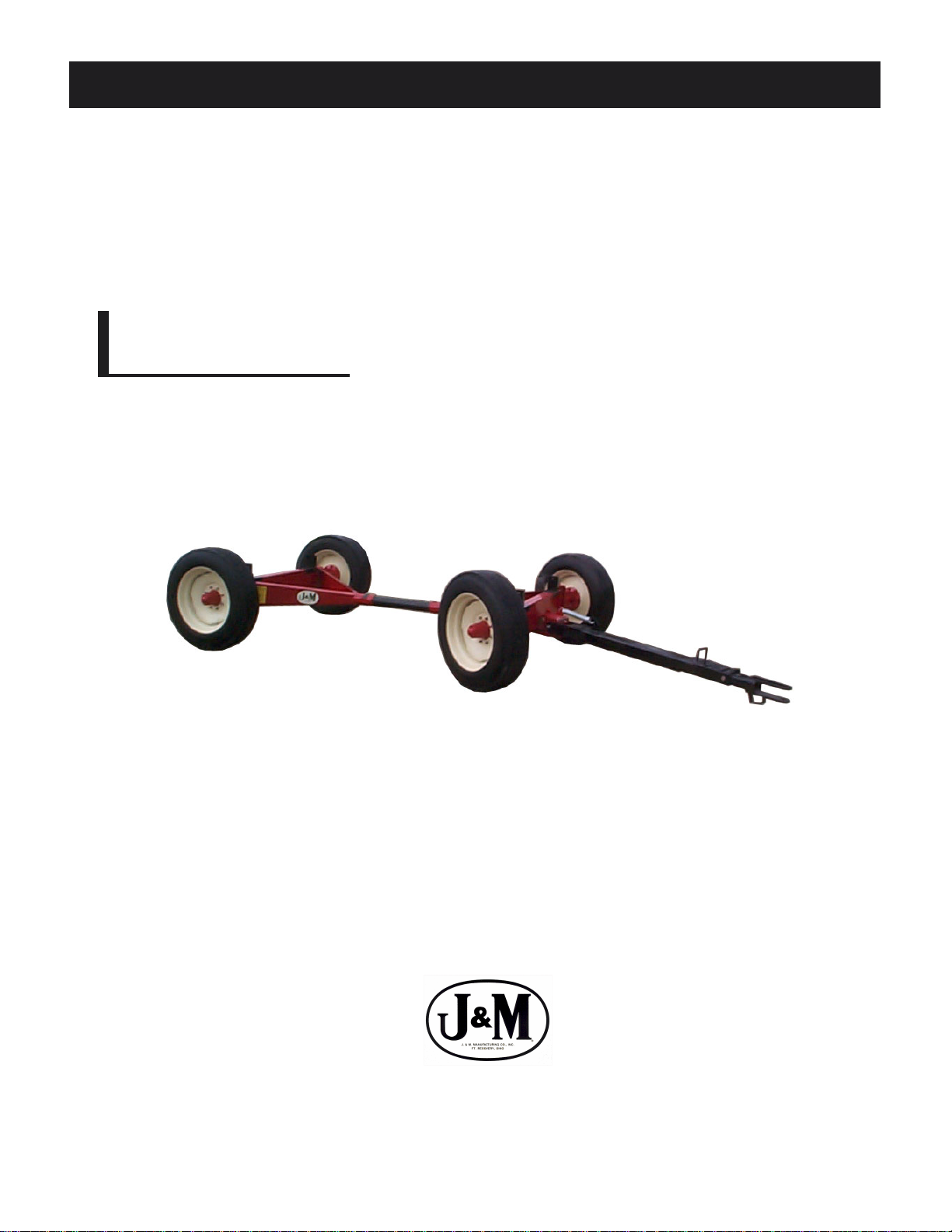
1592 Running Gear
JMMAN0101 (Rev . 05/01/05)
J. & M. Mfg. Co., Inc.
P.O. Box 547 Ft. Recovery, OH 45846
Ph: (419) 375-2376 Fax: (419) 375-2708
www.jm-inc.com
Page 2

TO THE DEALER:
Read manual instructions and safety rules. Make sure all items on the Dealer’s Pre-Delivery and Delivery Check Lists
in the Operator’s Manual are completed before releasing equipment to the owner.
The dealer must complete the Warranty Registration Card attached to the front inside cover of this manual and return
to J. & M. Mfg. Co., Inc. at the address indicated on the card. Warranty claims will be denied if the Warranty
Registration Card has not been completed and returned.
EXPRESS WARRANTY :
J. & M. Mfg. Co. Inc. warrants against defects in construction or materials for a period of ONE year . We reserve the right
to inspect and decide whether material or construction was faulty or whether abuse or accident voids our guarantee.
Warranty service must be performed by a dealer or service center authorized by J. & M. Mfg. Co. Inc. to sell and/or
service the type of product involved, which will use only new or remanufactured parts or components furnished by J.
& M. Mfg. Co. Inc. Warranty service will be performed without charge to the purchaser for parts or labor based on the
Warranty Labor Times schedule. Under no circumstance will allowable labor times extend beyond the maximum
hours indicated in the Warranty Labor Times schedule for each warranty procedure. The purchaser will be responsible,
however, for any service call and/or transportation of the product to and from the dealer or service center ’s place of
business, for any premium charged for overtime labor requested by the purchaser, and for any service and/or
maintenance not directly related to any defect covered under the warranty. Costs associated with equipment rental,
product down time, or product disposal are not warrantable and will not be accepted under any circumstance.
Each warranty term begins on the date of product delivery to the purchaser. Under no circumstance will warranty be
approved unless (i) the product warranty registration card (attached to the inside of the Operator’s Manual) has been
properly completed and submitted to the equipment manufacturer, and (ii) a warranty authorization number has been
issued by the equipment manufacturer. This Warranty is effective only if the warranty registration card is returned
within 30 days of purchase.
This warranty does not cover a component which fails, malfunctions or is damaged as a result of (i) improper
modification or repair, (ii) accident, abuse or improper use, (iii) improper or insufficient maintenance, or (iv) normal
wear or tear. This warranty does not cover products that are previously owned and extends solely to the original
purchaser of the product. Should the original purchaser sell or otherwise transfer this product to a third party, this
Warranty does not transfer to the third party purchaser in any way. J. & M. Mfg. Co. Inc. makes no warranty , express or
implied, with respect to tires or other parts or accessories not manufactured by J. & M. Mfg. Co. Inc. Warranties for
these items, if any, are provided separately by their respective manufacturers.
THIS WARRANTY IS EXPRESSL Y IN LIEU OF ALL OTHER W ARRANTIES OR CONDITIONS, EXPRESS, IMPLIED OR
STATUTORY, INCLUDING ANY IMPLIED WARRANTY OF MERCHANTABILITY OR FITNESS FOR PARTICULAR
PURPOSE.
In no event shall J. & M. Mfg. Co. Inc. be liable for special, direct, incidental or consequential damages of any kind. The
exclusive remedy under this Warranty shall be repair or replacement of the defective component at J. & M. Mfg. Co.
Inc’s. option. This is the entire agreement between J. & M. Mfg. Co. Inc. and the Owner about warranty and no J. & M.
Mfg. Co. Inc. employee or dealer is authorized to make any additional warranty on behalf of J. & M. Mfg. Co. Inc.
The manufacturer reserves the right to make product design and material changes at any time without notice. They
shall not incur any obligation or liability to incorporate such changes and improvements in products previously sold to
any customer, nor shall they be obligated or liable for the replacement of previously sold products with products or
parts incorporating such changes.
SERVICE:
The equipment you have purchased has been carefully manufactured to provide dependable and satisfactory use.
Like all mechanical products, it will require cleaning and upkeep. Lubricate the unit as specified. Observe all safety
information in this manual and safety signs on the equipment.
For service, your authorized J. & M. dealer has trained mechanics, genuine J. & M. service parts, and the necessary
tools and equipment to handle all your needs.
Use only genuine J. & M. service parts. Substitute parts may void the warranty and may not meet standards required
for safe and satisfactory operation. Record the model number and serial number of your equipment in the spaces
provided:
Serial No.: Date of Purchase:
Purchased From:
Provide this information to your dealer to obtain correct repair parts.
2
Page 3

15 TON RUNNING GEAR
SPECIFICATIONS
SPECIFICA TIONS
Capacity 15 T on
Weight (with tires)* 2,250 lbs
Width (c/c of tire) 86”
Spindle Size 3” diameter
Spring Balanced Tongue St andard
Ground Height (to top of axle) 26”
Rocking Bolster Optional
Tongue, Adjustable Quick Hitch Standard
Adjustable Center Pole St andard
Hydraulic Brake System Optional Disc Surge or Drum
Wheels - 8 bolt 22.5 x 13.5
*Weighed with 15-22.5 tires
GENERAL INFORMATION
TO THE OWNER:
The purpose of this manual is to assist you in operating and maintaining your running gear in a safe manner .
Read it carefully. It furnishes information and instructions that will help you achieve years of dependable
performance and help maintain safe operating conditions. If this machine is used by an employee or is loaned
or rented, make certain that the operator(s), prior to operating:
1. Is instructed in safe and proper use.
2. Reviews and understands the manual(s) pertaining to this machine.
Throughout this manual, the term IMPORT ANT is used to indicate that failure to observe can cause damage to
equipment. The terms CAUTION, WARNING and DANGER are used in conjunction with the Safety-Alert
Symbol, (a triangle with an exclamation mark), to indicate the degree of hazard for items of personal safety .
When you see this symbol, carefully read the message that follows and be alert to the possibility of personal
injury or death.
This Safety-Alert symbol indicates a hazard and means
A TTENTION! BECOME ALER T! YOUR SAFETY IS INVOL VED!
Indicates an imminently hazardous situation that, if not avoided, will
result in death or serious injury .
Indicates a potentially hazardous situation that, if not avoided, could
result in death or serious injury , and includes hazards that are
exposed when guards are removed.
Indicates a potentially hazardous situation that, if not avoided, may
result in minor or moderate injury .
Indicates that failure to observe can cause damage to equipment.
Indicates helpful information.
3
Page 4
GENERAL INFORMATION
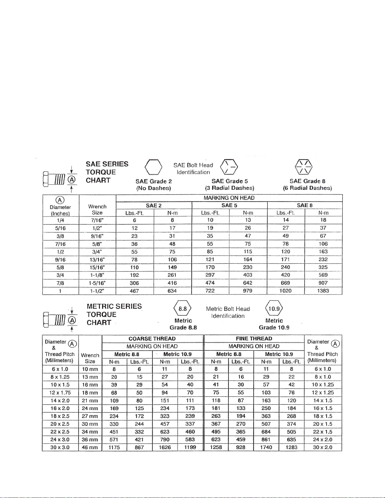
BOLT TORQUE CHART
Always tighten hardware to these values unless a different torque or tightening procedure is listed for a specific
application.
Fasteners must always be replaced with the same grade as specified in the manual parts list.
Always use the proper tool for tightening hardware: SAE for SAE hardware and Metric for metric hardware.
Make sure fastener threads are clean and you start thread engagement properly .
All torque values are given to specifications used on hardware defined by SAE J1701 & J1701M JUL 96.
4
Page 5

TABLE OF CONTENTS
INTRODUCTION 2
EXPRESS WARRANTY 2
SPECIFICATIONS 3
GENERAL INFORMA TION 3
BOLT TORQUE CHART 4
SAFETY RULES 6
SAFETY SIGNS 7
SET-UP INSTRUCTIONS 7-8
OPERATION 9
ROUTINE MAINTENANCE 9
P ARTS LIST/DIAGRAM 10
OPTIONAL HYDRAULIC DISC BRAKES 1 1-12
OPTIONAL HYDRAULIC DRUM BRAKES 13- 14
SERVICE RECORDS 15
5
Page 6

SAFETY RULES
A TTENTION! BECOME ALERT! YOUR SAFETY IS INVOL VED!
Safety is a primary concern in the design and manufacture of our products. Unfortunately , our efforts to provide
safe equipment can be erased by an operator’s single careless act. In addition, hazard control and accident
prevention are dependent upon the awareness, concern, judgement, and proper training of personnel involved in
the operation, transport, maintenance and storage of equipment.
Make certain that the operator(s), prior to operating is instructed in safe and proper use and reviews and
understands the manual(s) pertaining to this machine.
Read this manual before you operate this machine. If you do not understand any part of this manual, or need
more information, contact the manufacturer or your authorized dealer .
SAFETY
Understand that your safety and the safety of other persons is measured by how you service, and operate this
machine. Know the positions and functions of all controls before you try to operate them. Make sure to check
all controls in a safe area before starting your work.
The safety information given in this manual does not replace safety codes, federal, state or local laws. Make
certain your machine has the proper equipment as designated by local laws and regulations.
A frequent cause of personal injury or death is from persons falling of f equipment and being run over. Do not
permit persons to ride on this machine.
Travel speeds should be such that complete control and machine stability is maintained at all times. Where
possible, avoid operating near ditches, embankments and holes. Reduce speed when turning, crossing slopes
and rough, slick or muddy surfaces.
Collision of high speed road traffic and slow moving machines can cause personal injury or death. On roads,
use flasher lights according to local laws. Keep slow-moving-vehicle emblem visible. Pull over to let faster
traffic pass.
Never adjust, service, clean, or lubricate running gear until all power is shut off.
Keep all safety shields in place.
Keep hands, feet, hair and clothing away from moving parts while unit is in operation.
Make sure that everyone is clear of equipment before applying power or moving the machine.
Make sure that the running gear is fastened securely to the tractor by using the proper hitch pin, clip and safety
chains.
Never overload the running gear. Overloading the running gear is dangerous and can cause extensive damage.
Do NOT exceed load limit or speeds in excess of 20 MPH. Rims, hubs and bearings are designed for heavy
loads at slow speeds. Also be sure slow moving vehicle emblem is attached to rear of wagon.
Before unhooking the running gear from the towing unit, be sure to properly block the wheels to prevent the cart
from moving.
6
Page 7

SAFETY SIGNS
A TTENTION! BECOME ALERT! YOUR SAFETY IS INVOL VED!
Replace Immediately If Damaged or Missing!
IMPORTANT: Inst all new safety signs if the old signs are
destroyed, lost, painted over or cannot be read. When
parts are replaced that have safety signs, make sure you
install a new sign with each new part. New signs are
available from the manufacturer or your authorized dealer.
DC-113
SET-UP INSTRUCTIONS FOR RUNNING GEAR
Ref. # Description Part # Req’d
1 Sign, Caution DC-111 1
2 Sign, Fluid (Brakes) DC-113 1
3* Sign, Brakes Deactivated DC-122 1
4* Sign, Brakes Activated DI-123 1
DC-122
DI-123
* Decals DC-122 and DI-123
are located on the Brake LockOut Latch (#21) used on Disc
DC-111
Brake Systems Only.
IMPORTANT: Set-up work to be performed by qualified servicemen only.
Mount tires on the wheels and inflate per the tire manufacturer’s recommendations and instructions.
1)
Mount the wheels to the hubs and tighten the flat hub nuts to 260 ft. lb torque. Check the hub nuts
2)
after the first hour of operation, then every 10 hours of operation for the first 40 hours of use. These
nuts must be kept tight at all times. Wheels that are improperly installed on the running gear,
resulting in product failure, will nullify the warranty and shift the burden of liability to the owner/
operator of the equipment.
Slide the coupling pole into the front and back assemblies, slipping the collar in the back assembly .
3)
When mounting to a 540SD gravity box, spacing of the coupling pole (approximate distance between
holes on the coupling pole) should be 44”. Distance from center of axle to center of axle is
approximately 124”.
4)
Attach either the rocking bolster or the standards (box attachment brackets) to the running gear .
Fasten the tongue to the front assembly using the tongue bolt (remove paint from the bolt before
5)
attaching) and jam nut. Attach the tongue spring to the bracket on the tongue and hitch assembly.
For running gears without brakes, check underneath the tongue and make sure that the safety catch
(7/8” x 2 1/4” bolt w/spacer) is secure.
Mounting Brake Lines to Running Gear with Hydraulic Disc Brakes. IMPORTANT : Running Gears
6)
with Hydraulic Disc Brakes should be set up immediately after delivery from factory to prevent dirt
and moisture from entering brake system. Att ach the brake lines and hoses per drawing for Optional
Hydraulic Disc Brake System. Be careful not to over tighten the fittings and strip the threads.
Always use DOT 5 Silicone Brake Fluid or equivalent. On Optional Hydraulic Disc Brakes Systems,
be sure to remove paint from disc brake rotors before bleeding brake lines. Failure to
remove paint will cause brakes to not work properly . If running gear is stored for an extended
period of time, the brake discs will need to be cleaned with steel wool (be sure the brake
pads are not rusted fast to the brake disc). Also, check Caliper Retainer Area for free
movement. Free retainer and caliper from any seized paint or dirt by tapping retainer and
spring with a rubber or wood mallet.
7
Page 8

SET-UP INSTRUCTIONS FOR RUNNING GEAR (Continued)
IMPORTANT: Set-up work to be performed by qualified servicemen only.
7)
Adding Brake Fluid to Master Cylinder (for optional brake system).
IMPORTANT: Do NOT shake the brake fluid container . A VOID agitating the system when bleeding.
Do NOT “pump” the brake plunger . Instead, depress and release slowly .
Fill the master cylinder carefully, pouring the fluid down the side of the reservoir to minimize air
entrainment.
METHOD ONE (requires two people)
Close all bleed screws.
St art with the wheel furthest from the master cylinder. Slip a transp arent bleed hose on the bleeder
stem and place the other end of the hose in a clean container which is partially filled with fluid at all
times.
The first person depresses the brake plunger SLOWLY (take 3-5 seconds). THEN the second
person opens the bleed screw. He then closes the bleed screw BEFORE the first person SLOWLY
releases the plunger (3-5 seconds). Continue until there is no evidence of air in the bleed hose.
Continue with remaining wheel working from the longest to the shortest distance from the master
cylinder. T op of f master cylinder as needed to prevent reintroducing air into the lines.
REMEMBER:
1) Depress plunder slowly
2) Open bleed screw
3) Close bleed screw
4) Release plunger slowly
METHOD TWO (one person)
Attach bleed hose to rear wheel as in method one. Open bleed screw . SLOWLY depress plunger (3-
5 seconds) Let plunger return SLOWLY (3-5 seconds). Repeat until line is air free. Close bleed
screw. Top off master cylinder as needed to prevent reintroducing air into lines.
Repeat with remaining wheel.
Contamination with dirt, water , petroleum products or other materials may result in brake failure or
costly repairs.
8)
MOUNTING WHEELS
Figure One shows the proper way to mount wheels with straight holes.
(22.5 x 13.5 wheels)
Use flange wheel nut (valve stem is on the outward side of the tire).
Wheels that are improperly installed on running gears, resulting in product
failure, will nullify warranty and shift the burden of liability to the owner/
operator of the equipment.
IMPORTANT: Make sure to properly attach the gravity box (or other equipment) to the running gear.
Bolt all four corners of the gravity box runners to the running gear. (If the box is used in rough terrain
and it is not equipped with a rocking bolster, bolt a minimum of two corners and chain (or cable) the
remaining corners to allow more box flexibility).
FIGURE ONE
8
Page 9

OPERATING INSTRUCTION / MAINTENANCE
BE CERTAIN THAT ALL POWER IS SHUT OFF BEFORE SERVICING EQUIPMENT.
Before equipment is put into service:
Has this manual and the operator’s manual on the gravity box been read and clearly understood by the
operator(s) of this machine?
Have all braces, bolts, nuts, lug bolts, and lug nuts been checked to ensure that they are properly fastened?
Is the running gear properly fastened to the tractor? Use a good quality hitch pin with clip and safety chain.
SAFETY CHAIN USER INSTRUCTIONS
a) Secure the safety chain by looping it around the tongue support located on the underside of the outer
tongue. Extend the chain through the support located on the underside of the inner tongue and connect to
the towing machine’s attaching bar .
b) Be sure to run the safety chain through the support on the underside of the inner tongue. This will
provide an intermediate support for the safety chain.
c) Do Not allow more slack than necessary for articulation (max. 9 inches)
d) Do Not use any intermediate support as the attaching point.
e) Store the safety chain by securing it around the tongue support s.
f) Replace the safety chain if one or more links or end fittings are broken, stretched or otherwise damaged
or deformed.
Have all danger, warning, caution and import ant signs on the equipment been read and clearly understood? If
employees or others use or are near this equipment, make sure that they also have read and understood all
danger, warning caution and important signs on the equipment and have also read the operator’s manual.
Have the wheel bearings been inspected? Repack with grease if needed. Grease both the tongue bolt and the
hitch bolt.
750-16 OWNER’S MANUAL
Do not exceed the load limit of the unit.
BRAKING SYSTEM REQUIREMENTS:
Tow Loads Safely
Stopping dist ance increases with speed and weight of towed loads, and on slopes. T owed loads with or without
brakes that are too heavy for the tractor or are towed too fast can cause loss of control. Consider the total
weight of the equipment and its load.
Observe these recommended maximum road speeds, or local speed limits which may be lower:
If towed equipment does not have brakes, do not travel more than 32 km/h (20 mph) and do not tow
loads more than 1.5 times the tractor weight.
If towed equipment does have brakes, do not travel more than 40 km/h (25 mph) and do not tow
loads more than 4.5 times the tractor weight.
Ensure the load does not exceed the recommended weight ratio. Use additional caution when towing loads
under adverse surface conditions, when turning, and on inclines.
IMPORT ANT:
Keep the tires properly inflated. Both under inflation and over inflation can greatly reduce tire life.
Inspect bracing and welds and repair if needed. Failure to repair could cause extensive damage and greatly
reduce the life of the unit.
Inspect tie rods and replace the bronze bushings in the steering assembly when needed.
Repack the bearings in the hub assemblies once a year or as needed. Use a good quality bearing lubricant
such as Bearing Gard MK1 or equivalent. NOTE: Grease zerks on hub caps are for between scheduled
service lubrication.
If equipped with disc brakes, inspect the brake pads periodically for wear and for brake line damage. Check
fluid in the master cylinder and inspect for dirt or corrosion on the inside wall of the master cylinder. Clean and
replace with new Silicone Brake Fluid (DOT 5) if needed. Wagons with brakes should be stored in a clean dry
place when not in use.
9
Page 10

RUNNING GEAR P ARTS LIST
# Part # Description Qty
1 OT-1215NS Adj . Tongue Outer Wel dm ent 1
2 IT-1215 NS Adj . Tongue Inner Weldment 1
3 TL-1215NS Tongue Latch Wel dment 1
4 SS -615 NS Small S pri ng i n La tch 1
5 LS-12 15 Latch Pivot Sh aft , 1" Dia. 1
6 CP-112 Cotter Pin 2
7 TT-13 Tel es c opi ng Tongue Complet e 1
8 TB-1215 Tongue Pivot Bolt 1
9 HN-114 Regu l ar Hex Nut 4
10 KP-121 5 King Pi n B o l t 1
11 HW-1215 Hi tch W el dm e nt 1
12 BB-34 Bronze Bus hi ng, 3/4" 4
13 SB-34 Special S tep Bolt , 3/4" 4
14L TRE-1L Tie Rod E nd, Left 2
14R TRE - 1R Ti e Rod End, Ri g ht 2
15L HN-1 L 1" -1 4 Hex Nut, Left 2
15R HN-1R 1"-14 Hex Nut , Right 2
16 TR-20 Tie Rod, 1" Dia. 2
17L S A -15L Spi nd l e & " U" Assy w/ A rm , Left 1
17R SA-15R Spindle & "U" Assy w/Arm, Right 1
18 EB-134 End S pindle Bronze Bushing 4
19 SPB-134 Spi nd l e B ol t x 13 1/2 " 2
20 HN-134 1 3/4" Hex Nut 2
21 FA-1215 F ront Axl e Weldment 1
22 RA-15 Rear Axle Assembly 1
23 RS-15 Rear Spindle 1
# Part # Description Qty
24 M B-346 3/ 4" x 6" B ol t 2
25 LN-34 3/4" Lock Nut 2
26 TS-615 Large Tongue Spring 1
27 CP-4L Coupling Po l e 1
28 ST-1215 Standards (optional ) 4
29 M B-126 1/ 2" x 5 1/2" Bolt 8
30 HN-12 1/2" Lock Nut 8
31 CL-412 Collar to Coupling Pol e 1
32 107751 Hub Incl. Lug B olt & Nuts 4
33 29968 Grease S eal 4
34 387-AS Inner Bearing (Large) 4
35 105771 Out er Bearing (Sm all ) 4
36 106247 S pindle Washer 4
37 106248 S lo t ted Spindl e Nut 4
38 CP-316 Cotter Pi n 4
39 103213 Dus t Cap 4
40 WR-22. 5-13 . 5 W heel Ri m , 8 ho le , 22.5x13. 5 4
41 WB-15 Wheel Stud 32
42 WB-15F Wheel Nut 32
43 1633 Grease Fit t i ng 4
44 SB-212 Spa c er Blocks 2
45 78214-BS 7/8" x 2 1/4" Bolt with spac er 1
46 382A Inner Cup, Large 4
47 105770 Out er Cup, Sm all 4
10
Page 11

Parts List for New Style
Hydraulic
For 2004 Running Gears and newer,
beginning with the corresponding
serial number...
Model Serial #
1384L 13227
138 4S 01666
1484 02256
1592 03669
2492 01650
DISC Brakes
A
B
T ongue Assembly
A
3
4
6
7
Rear Brake Assembly
B
14
12
21
16
22
11
16
20
23
18
24
15
13
15
6
9
8
6
7
2
17
10
5
1
19
15
5
25
Note: The hole in the Brake Limiter (Item #7) should be
5
positioned toward the rear of the tongue.
34
35
36
26
IMPORTANT: Remove paint from both
sides of brake rotor BEFORE use.
Failure to remove paint and debris may
cause brakes to not work properly.
31
42
46
38
Rear Axle Brake System
11
26
45
34
44
3332
31
42
51
Page 12

Parts List for New Style
Hydraulic
DISC Brakes
Brake Line Assembly
C
For 2004 Running Gears and newer,
beginning with the corresponding
serial number...
Model Serial #
1384L 13227
138 4S 01666
1484 02256
1592 03669
2492 01650
D
# Part # Description Qty
1 OTW-1324 Outer Tongue W el dm ent 1
2 ITW -1324 Inner Tongue Weldment 1
3 TL-1324 Tongue Latch 1
4 SS-615NS Sma l l S pri ng In Lat ch 1
5 17G2B 1" x 7" Bolt (Grade 2) 3
6 1LN 1" Lock Nut 3
7 BL-58 Brake Limiter 2
8 19G8B 1" x 9" Bolt (Grade 8) 1
9 CS-178714 Compression Spri ng 1
10 1RN 1" Regular Nut 2
11 TB-1215 Tongue Bolt 1
12 HN-114 1 1/4" Hex Nut 1
13 SM C-1 Sh i eld for Ma ster Cyl i nder 1
14 124-JB 1/ 2" x 4" J-Bol t 2
15 12-N 1/2" Regular Nut 4
16 381-FB 3/ 8" x 1" Fl ange B ol t 6
17 BLOL-1 Brake Lock O ut Latch 1
18 MCA-DC1 M ast er Cylinder Ass embly 1
19 RCMC-1324 Replacem e nt Cap for M/Cyl. 1
20 383G8B 3/ 8" x 3" Bol t (Grade 8) 2
21 PRE -1 Pl unger Rod E nd 1
22 MB M C-DC2 Mounting Bracke t (2 pcs) for
23 38-FN 3/8" F l ange Nut 4
24 38-LN 3/8" Loc k Nut 2
25 PP -1D Pl unger P ol e 1
26 CA-1424 B rake Caliper A ssembly 2
27 BP -1424 Brak e Pad 4
28 SCA -1415 Seal for Caliper Ass em bl y 4
29 BCA -1415 Boot for Cali per Ass em bl y 4
30 CCA-1415N Cup for Caliper A ssembl y 4
Parts List
Master Cylinder
46
48
47
# Part # Descri p tion Qty
31 BD-1314 B rake Disc (13-14 Ton) 2
31 BD-15 B rake Disc (15 Ton) 2
31 BD-24 B rake Disc (24 Ton) 2
32 SP -1324L B rake Support Arm (Left) 1
33 SP -1324R Brak e Support Arm (Right) 1
34 BG-1 Brake Guard (13-15 Ton) 2
34 G-24 Brak e G uard (24 Ton) 2
35 RT-1415 Retainer with Bolt 2
36 TS-1415 Tension S pri ng 2
37 RB-1415 Rubber B o ot on Mast er Cylinder 1
38 GR-1415 Rubber Gromm e t 2
39 SK MC-1324 Seal K it for Master Cylinde r 1
40 W S-24 Wire Spri ng (anti-ratt l e) 2
41 DOT5-BF Cont ai ner DOT 5 Brake Fluid 2
42 12114-G5 1/2" x 1 1/4" Bolt w/Lock Wash. 12
43 WB -41L Wheel Stud (
44 H-812-1B Hub, F aced for Brakes (13-14 T) 2
44 107751-B Hub, Faced for Brakes (15T) 2
44 W -871B Hub, Faced for Brakes (24T) 2
45 BS -24 B leeder Stem 2
46 CF-1324 Fi tting for Caliper 2
1
47 FMC-1324 Fi tting for Mas ter Cylinder 1
48 HH-1424 1/4" x 24" Hy dra ul i c Hose 1
50 ST-96 3/16" Brake Li ne x 96" (13-15T) 1
50 ST-120 3/ 16" Brake Line x 12 0" (24 T) 1
51 ST-53 3/16" Brake Li ne x 53" 2
52 10606 Tee 1
53 SC-1324 S p ri ng Cli ps 6
50
51
52
51
Long Knurl)( 13-14T)
53
46
16
Instructions for Adjusting the Plunger Rod
E
1. Pull on the tongue so the latch is tight against the stop.
2. Loosen the Hex Nut between the Plunger Rod and Plunger Pole. Adjust the Plunger Rod so there is 1/8” to
3/16” play between the plunger rod and master cylinder. IMPORTANT: If there is NO Free Travel between the
activator and the master cylinder, the brakes will always be on, allowing the brakes to get hot and fail.
3. Add Brake Fluid (DOT 5) to the master cylinder and bleed air from the lines.
12
Page 13

Parts List for
Hydraulic
DRUM
Brakes
Brake Line Assembly
A
33
35
36
38
T ongue Assembly
B
3
4
6
19
14
37
12
21
16
36
22
11
16
20
23
18
24
17
15
13
15
1
9
8
6
7
10
5
7
2
15
25
Note: The hole in the Brake Limiter (Item #7) should be
5
positioned toward the front of the tongue.
Parts List
C
# Part # Description Qty
1 OTW-132 4 Outer Tongue W eldment 1
2 ITW -1324 Inner Tongue W eldm ent 1
3 TL-1324 Tongue Latch 1
4 SS -615NS Small S pring In Latch 1
5 17G2B 1" x 7" B ol t (Grade 2) 2
6 1LN 1" Lo c k Nut 2
7 BL -58 Brak e Li m i ter 2
8 19G8B 1" x 9" B ol t (Grade 8) 1
9 CS-178714 Compres s i on Spring 1
10 1RN 1" Regular Nut 2
11 TB-1215 Tongue B olt 1
12 HN-114 1 1/4" Hex Nut 1
13 SM C-1 Shield for Master Cyli nder 1
14 124-JB 1/ 2 " x 4" J-Bol t 2
15 12-N 1/2" Regular Nut 4
16 381-F B 3/ 8" x 1" Fl ange B ol t 6
17 FMC-1324 Fit t ing for Mast er Cyl inder 1
18 MCA-DR1 Master Cylinder Ass embly 1
19 RCMC-1324 Replacement Cap for M/Cyl. 1
20 383G 8B 3/ 8" x 3" B ol t (Grade 8) 2
21 P RE-1 Plunger Rod E nd 1
# Part # Description Qty
22 MBMC-DR2 Mounting Brack et (2 pcs) for
Master Cylinder
23 38-FN 3/8" Fl ange Nut 4
24 38-LN 3/ 8" Loc k Nut 2
25 PP-1D Plunger Pole 1
26 RB-1415 Rubber Boot on Master Cylinder 1
27 GR-1415 Rubber Grommet 2
28 SK M C-1324 S eal K i t for Mast er Cyl inder 1
29 DOT5-B F Container DOT 5 Brake Fl uid 2
30 WB-41L Wheel Stud
31 H-812-1B Hub, F aced for Brakes (13-14T) 2
31 107751 -B Hub, Faced for Brakes (15T) 2
31 W-871B Hub, Faced for Brakes (24T) 2
32 BS -24 Bleeder St em 2
33 HH-1424 1/ 4 " x 24" Hy draul i c Hose 1
35 ST-96 3/16" Brake Line x 96" (13-15T) 1
35 ST-120 3/ 16" Brake Line x 120" (24T) 1
36 ST-53 3/16" Brake Line x 53" 2
37 10606 Tee 1
38 SC-1324 Spring Clip 6
(Long K n ur l ) ( 1 3-15T) 16
13
1
Page 14

Parts List for Drum Brake Assembly
D
# Part # Description Qty
1 24737 B ack Pl ate As s e m bl y 1
2 9739 Front B rake Shoe A ssembl y 1
3 9745 Front S hoe Lever 1
4 9775 Rear Shoe Lever 1
5 9776 W heel Cyli nder Ass embly - Ri gh t 1
6 9777 W heel Cyli nder Ass embly - Le ft 1
7 23457 S crew & Loc kwasher 2
8 & 9 23324 Adjusting Screw & Pivot Nut 1
10 9782 S oc k et - A djus t i ng Screw 1
11 9783 Push Rod - Wheel Cylinder 1
12 9784 Spri ng Adjust i n g S crew (Yell ow) 1
13 9785 Spri ng - Fron t Lever (Red) 1
14 9786 Spri ng - Rear Shoe (Orange) 1
15 9788 Pi n - S hoe Hold Down 2
16 9789 Cup - Shoe Hold Down 4
17 9790 Spri ng - Fr ont Hol d Down (Y el l ow) 1
18 9791 S pring - Rear Hold Down (Blac k ) 1
19 9254 Cover Pl ate - Adjusting Hol e 1
20 7778 Retai n in g Ring 1
21 17406 Hex - Locknut 5/16" NC 1
22* 9731 Toggle Lin k, Righ t 1
23* 9732 Toggle Lin k, Left 1
24* 9792 P ark i n g Lever, Right 1
25* 9793 P ark i n g Lever, Left 1
26* 9794 S pri ng Washer 1
27* 9795 Retainer 1
28 9743 Travel Li nk 1
29 7949 Travel Li nk B ol t - Hex Cap S crew
5/16" NC x 5/ 8 "
30 9796 Pi n-F ront S h oe - wi t h P ark
Linkage
30 12560 P i n-Fron t S h oe - without Park
Linkage
31 6814 Spri ng - F ront Shoe 1
32 9797 Pl ug - Pl ast ic 1
33 7972 Hex Nut 1/2" NF 4
34 7955 Cap Sc rew 1/2" NF x 1" 4
35 7937 Loc k washer 1/2" 4
36 9404 Pl ug - Pl ast ic 1
37* 17194 P arki ng St rut
38* 16090 S pri ng - P arking St rut
15845 Wheel Cyl i nde r Repa i r Kit - 1 1/8" 1/2
Adjusting the Drum Brakes
E
It is necessary to rotate the wheels in the direction of
forward rotation only when making adjustments.
The brake adjustment nut is located behind a slot at
the bottom of the backing plate. Tighten the nut until
you cannot rotate the wheel by hand, then back off the
1
adjustment 18 to 20 notches.
1
ROTATE THE DRUM IN THE DIRECTION OF
FORWARD ROT A TION ONL Y
1
Hydraulic Lines
F
Use care in shaping brake lines to avoid sharp bends
or kinks. Be sure and use a “Double Flaring” type of
tool on steel tubing to assure tight leakproof
connections. Be sure and use hydraulic rubber hoses
at points of flexing. Anchor hose ends to avoid stress
on tubing.
14
Page 15

SERVICE / MAINTENANCE RECORD
DATE DESCRIPTION NOTES
15
 Loading...