

Page 1
ZR800-CW
Subwoofer
owner’s manual
Thank you for choosing a JL Audio Evolution ZR Component Woofer for your
automotive sound system. With proper installation, your new speaker
will deliver years of listening pleasure.
We strongly recommend that you have your new Evolution speaker installed
by your authorized JL Audio dealer. The installation professionals employed by your
dealer have the necessary tools and experience to disassemble your interior panels,
install your new speakers and reassemble your vehicle properly. If you prefer to
perform your own installation, please read this instruction manual
completely before beginning the process.
Page 2
B
E
A
C
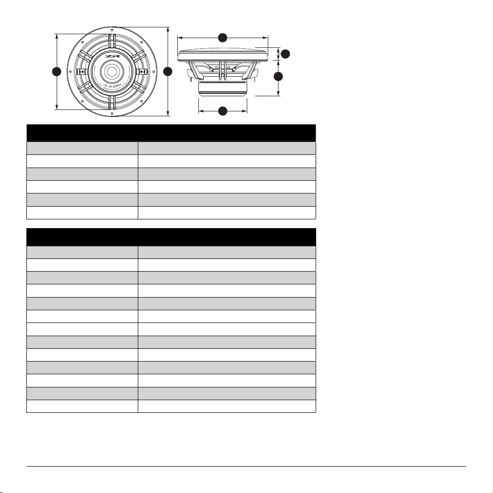
Woofer Physical Dimensions
Frame Outer Diameter (A) 8.26 in. / 209.8 mm
Grille Tray Outer Diameter (B) 8.49 in. / 215.6 mm
Magnet Outer Diameter (C) 4.54 in. / 115.3 mm
Frontal Grille Protrusion (D) 1.17 in. / 29.7 mm
Mounting Hole Diameter (E) 7.125 in. / 181.0 mm
Mounting Depth (F) 3.39 in. / 86.0 mm
ZR800-CW SPECIFICATIONS
D
F
Cast Alloy Frame
Elevated Frame Cooling
(U.S. Patent #6,219,431 & #6,229,902)
DMA-Optimized Motor Sys tem
Mineral-Filled Polypropylene Cone
Santoprene Surround
1.75-in. / 44 mm Voice Coil
Kapton® Former
Progressive Roll Spider
Ferrite Magnet
Precision-Built in Miramar, Florida - USA
Continuous Power Handling (Pt): 125W
(RMS Method)
Peak Music Power: 225 W
Recommended Power Range: 75-150W (RMS)
Frequency Response: 50 Hz - 500 Hz (± 3 dB)
Subwoofer Parameters ZR800-CW
Free Air Resonance (Fs): 46.27 Hz
Electrical “Q” (Qes): 0.702
Mechanical “Q” (Qms): 11.667
Total Speaker “Q” (Qts): 0.662
Equivalent Compliance (Vas): 0.787 ft / 22.29 litres
One-way, Linear Excursion (Xmax)*: 0.34 in. / 8.6 mm
Efficiency (1W/1m)**: 87.0 dB SPL
Effective Piston Area (Sd): 33.34 in / 0.0215 m
Included Components a nd Parts:
• One ZR800 -CW 8.0-inch (200 mm) Woofer
• One Metal Woofer Grille with ABS Grille Tray
• One Self-Adhesive JL Audio Nameplate for Grille
• Butyl Adhesive Putty for Woofer Grille
• Eight #8 x 1.25 inch (32 mm) Sheet Metal Screws
• Eight Mounting Clips for Woofer Mounting
• One 6.4 mm Female Crimpable Conn ectors
• One 4.7 mm Female Crimpable Connectors
DC Resistance (Re): 3.935 ohm
Nominal Impedance: 4 ohm
Infinite Baffle Use: Yes
Enclosure Use: Yes (Sealed & Ported)
Power Handling (continuous): 125W
* Xmax specifications are derived via one-way voice coil overhang method with no correction
factors applied.
** Efficiency (1W/1m) is not an accurate indicator of a subwoofer’s output capability and should
not be used as a comparison to other subwoofers to determine which one is “louder” !
2 JL AUDIO ZR800-CW
All specifications are subject to change without notice.
Page 3

APPLICATION INFORMATION
The ZR800-CW is a powerful 8-inch
component woofer designed to operate
in automotive sound systems reproducing
the frequency range between 30 Hz
and 400 Hz. It can be used in infinitebaffle or enclosed applications as an
extremely potent, dedicated midbass speaker or as a full woofer.
Active Filtering is Recommended:
When used as a mid-bass speaker, we
recommend the use of dedicated amplifier
channels and active filtering (electronic
crossovers) with the ZR800-CW.
The ZR800-CW maintains smooth frequency
response characteristics up to 500 Hz, so it
is advisable to cross it over with mid-range
speakers at 300-400 Hz to ensure a smooth
transition. Pushing it higher than this range
may result in uneven response which may
require equalization to correct.
Infinite Baffle:
As a dedicated mid-bass speaker operating
above 50 Hz (with active filtering) the
ZR800-CW can be safely operated at
power levels momentarily exceeding 200
watts per woofer. When operating below
50 Hz as a true woofer, power should be
limited to no more than 125 watts per
woofer in infinite baffle applications.
Enclosed Operation:
The ZR800-CW can also be used in sealed
or ported enclosures as recommended
in this manual. Again, power should be
limited to no more than 125 watts per
woofer if being played below 50 Hz.
More power can be used if appropriate
active high-pass filtering is applied.
JL AUDIO ZR800-CW 3
Page 4

GETTING STARTED
• Turn off the audio system. It is also
advisable to disconnect the negative
(–) terminal of your vehicle’s battery
whenever performing installation work.
• Before cutting, drilling or inserting any
screw, check clearances on both sides
of the planned mounting surface. Also
check for any potential obstacles, such
as window tracks and motors, wiring
harnesses, etc. Check both sides of the
vehicle, many vehicles are not symmetrical!
• Always wear protective eyewear.
SPEAKER INSTALLATION
Run speaker wire to the desired mounting
location. If you are running wires into a door,
use existing factory wiring boots whenever
possible. If you are drilling new holes, file
their edges and install rubber grommets
into each hole. Then, cover the wires with a
protective PVC sleeve and run them through
the door jamb. Make sure that the wires will
clear door hinges and other structures in the
door. If you are unsure about any part of this
process, please contact your JL AUDIO dealer
for installation help.
WARNING
!!
Double check the clearance for both
speakers before proceeding. Many cars are
different from one side to the other!
Select an even surface. Tightening a
speaker onto an uneven surface can damage
it. Use the supplied template to mark the
desired mounting location. Mark the center
and the outline of the mounting hole as
well as the mounting screw positions. Before
drilling or cutting on your interior panels,
use a utility knife to cut any fabric, vinyl or
leather from hole locations. These materials
can easily be snagged by a drill or a saw,
causing damage to the panel and possible
bodily injury. Drill eight 1/8-inch (3 mm)
holes for the speaker’s mounting screws at
the positions you have marked. Also drill
a pilot hole in the center of the speaker
mounting hole at this time. Then, using a
saber saw, make the circular cut out for the
speaker. File any rough edges. Insert the
mounting clips with the flat side towards
the speaker as shown in Diagram B (below).
It is absolutely vital that the speaker frame
fits into the mounting hole cleanly. This must
be checked prior to tightening the screws.
Do not force the frame into a hole that is
too small. Do not tighten the speaker onto
an uneven surface. This will damage your
speakers. The speaker should also fit so that air
does not leak around the mounting flange. Air
leaks will cause a severe degradation in sound
quality. Seal any air leaks with an automotivegrade sealant material.
Connect the speaker wires, observing
correct polarity, and install the speaker and
grille tray as shown in Diagram A (page 5).
Hand-tighten the screws evenly to avoid
bending the speaker frame!
Break off small pieces of the supplied butyl
adhesive putty and place them on the inside
of each grille tray. This adhesive will hold
the grille in place firmly and prevent rattling.
Then insert the metal grille into the grille tray,
squeezing gently around its edge until it seats
firmly into the tray.
4 JL AUDIO ZR800-CW
Page 5

Diagram A:
Typical Woofer Installation
JL AUDIO ZR800-CW 5
Page 6

ENCLOSURE SPECIFICATIONS
Driver Recommended Sealed Design
ZR800-CW
Volume
(net int.)
0.750 ft
21.2 litres
External Dimensions
(Width x Height x Depth)
15.5 in. x 12 in. x 10.5 in.
394 mm x 305 mm x 267 mm
Sealed Design Ported Design
Driver Recommended Ported Design
ZR800-CW
Volume
(net int.)
1.125 ft
31.9 litres
Enclosure External Dimensions
(Width x Height x Depth)
18 in. x 15 in. x 10.5 in.
457 mm x 381 mm x 267 mm
Round Port Specs
(Inner Diameter x Length)
51 mm x 127 mm
2 in. x 5 in.
F3
(Hz)
Fc
(Hz)
Qtc
60 80.73 1.155
Tune to:
(Hz)
F3
(Hz)
32 50
The enclosure recommendations listed are external dimensions which assume the use of 3/4” (19mm) thick material. If you are using 5/8” (16mm) thick
material, subtract 1/4” (6.5mm) from each dimension. Do not use any material with a thickness of less than 5/8” (16mm) as this may compromise the rigidity
of the enclosure.
All enclosure volumes listed are net internal volumes! Box volume displacement, port displacement and brace displacement must be added to obtain
the final gross internal volume. All enclosure dimensions listed have already taken this into account.
6 JL AUDIO ZR800-CW
All specifications are subject to change without notice.
Page 7

RECOMMENDED CONTINUOUS RMS POWER RANGE FOR ONE COMPONENT WOOFER:
MEDIUM GRAY MINIMUM:
From a reliab ility standpo int, this zone
represents a very comfortable operating
power ran ge for each d river. This le vel
of power wi ll not stress the woofe r but
will not ex trac t all of its pe rform ance
potential, either.
Use of less tha n the minimum p ower
level will n ot damage the woofer, but may
result in unsatisfactory performance.
When designing systems with our drivers, it is very important to achieve a good power match between the subwoofer amplifier and the subwoofer driver's capabilities.
The power levels listed in the above chart represent continuous (RMS) amplifier power per woofer and assume that the user will regularly make full use of that power
without drastically overdriving the amplifier(s). Make sure you factor system impedance and the total number of subwoofers into your calculations. Adhering to these
power recommendations will result in systems that are both reliable and enjoyable.
LIGHT GRAY OPTIMUM:
This zone represents the best
compromise between long-term
reliability, high-output and low-distortion
performance. This power level is lower
than the woofer’s continuous power rating
(as publish ed in its sp ecifi cations), but
you will still be taking advant age of the
woofer’s, low-distortion performance
range wi thout undue risk of f ailure.
DARK GRAY MAXI MUM:
Slightly more SPL will be gained by
pushing the power into t his zone, but
typic ally not mo re than 2dB, co mpared to
the light gr ay zone. The subwoofer driver
is designed to operate safely up to this
power ran ge, but not b eyond. Op erate
with caution.
BLACK WARRANTY VOID:
We do not reco mmend op erating
woofers at this level of power. In this
zone, the re is a very high probab ility
that the dri ver will fa il due to exces sive
heat and/or mechanical stress.
Drivers operated at these levels of
power ar e NOT covered un der warrant y.
JL AUDIO ZR800-CW 7
Page 8

LIMITED WARRANTY USA AUTOMOTIVE SPEAKER SYSTEMS
JL AUDIO warrants this speaker to be free of defects in materials
and workmanship for a period of one (1) year from the original date
of purchase.
Damage caused by the following is not covered under warranty:
accident, misuse, abuse, product modification or neglect, failure
to follow installation instructions, unauthorized repair attempts,
misrepresentations by the seller. This warranty does not cover
incidental or consequential damages and does not cover the cost
of removing or reinstalling the unit(s). Cosmetic damage due to
accident or normal wear and tear is not covered under warranty.
This warranty is not transferable and applies only to the
original purchaser of the product from an authorized JL AUDIO
dealer. Warranty is voided if the factory-applied product serial
number is removed or defaced.
Should service be necessary under this warranty for any reason due
to manufacturing de fect or malfunction, JL AUDIO will, at its disc retion,
repair or replace the defective product with new or remanufactured
product at no charge.
Any applicable implied warranties are limited in duration to the
period of the express warranty as provided herein beginning with
the date of the original purchase at retail, and no warranties, whether
express or implied, shall apply to this product thereafter. Some
states do not allow limitations on implied warranties, therefore these
exclusions may not apply to you. This warranty gives you specific
legal rights, and you may also have other rights which vary from state
to state.
If you need service on your JL AUDIO product:
All warranty returns should be sent to JL AUDIO freight prepaid
through an authorized JL AUDIO dealer and must be accompanied by
proof of purchase (a copy of the original sales receipt.) Direct returns
from consumers or non-authorized dealers will be refused unless
specifically authorized by JL AUDIO with a valid return authorization
number. Warranty expiration on products returned without proof
of purchase will be determined from the manufacturing date code.
Coverage may be invalidated as this date is previous to purchase date.
Return only defective components. Non-defective items received
will be returned freight-collect. Customer is responsible for shipping
charges and insurance in sending the product to JL AUDIO. Freight
damage on returns is not covered under warranty. Always include
JL Audio customer service: (954) 443-1100 during normal business hours (Eastern Time)
Products purchased outside the United States of America are covered only by that country’s distributor and not by JL Audio, Inc.
Printed in USA JLA-ZR800CW-0608-SKU#011267
For Service Information in the U.S.A. please call:
JL Audio, Inc
10369 North Commerce Parkway, Miramar, FL 33025
International Warranties:
 Loading...