


XR653-CS
6.50-inch (160 mm) 3-Way Component Speaker System
o w n e r ’ s m a n u a l
Thank you for choosing JL Audio Evolution XR Coaxials for your automotive sound system. With proper installation, your new speakers will deliver years of listening pleasure.
We strongly recommend that you have your new Evolution speakers installed by your authorized JL Audio dealer. The installation professionals employed by your dealer have the necessary tools and experience to disassemble your interior panels, install your new speakers and reassemble your vehicle properly. Also, keep in mind that your warranty coverage extends to 1 year if your system is installed or approved by your authorized JL Audio dealer. If you prefer to perform your own installation, please read this instruction manual completely before beginning the process.

XR653-CS SPECIFICATIONS:
Woofers: Mineral-filled polypropylene cone body, 1-inch (25mm) voice coil, low-profile/symmetrical- roll spider, butyl rubber surround.
Midrange Drivers: Treated pulp cone body, 1-inch (25mm) voice coil, low-profile/
symmetrical-roll spider, butyl rubber surround.
Tweeters: 1-inch (25 mm) aluminum dome tweeter with soft, rubber suspension, neodymium magnet, ferrofluid cooled and damped.Variable mounting system with swivel/rotation capability.
Crossover Networks: 3-way network with 2nd Order low-pass, 2nd Order bandpass and 2nd order high-pass circuit. Premium capacitors and inductors. 4-position adjustable tweeter output level. Polyswitch tweeter protection.
Continuous Power Handling:
70 Watts (RMS Method)
Frequency Response: 48 Hz - 25 KHz (± 3 dB)
Efficiency @ 1W/1m: 90.5 dB
Nominal Impedance: 4 ohms
INCLUDED COMPONENTS AND PARTS:
•Two XR650-CW 6.50-inch (160 mm) woofers
•Two XR400-CM 4-inch (100 mm)
midrange drivers
•Two XR100-CT 1-inch (25 mm) tweeters
•Two XR653-CSxo 3-Way Crossover networks
INCLUDED HARDWARE:
•Two Flush-Mount tweeter fixtures with metal spring clips and optional trim rings
•Two Surface-Mount tweeter fixtures
•Two 6.5-inch Metal Grilles and Grille Trays
•Two 4-inch Metal Grilles and Grille Trays
•Two 4-inch Frame Adaptors and Flush-Mount Rings
•Butyl adhesive putty for grilles
•Twenty #8 x 1 1/4-inch (30 mm) sheet
metal screws
•Sixteen #8 Mounting Clips
•Eight #6 x 1 1/4-inch (30 mm) sheet metal screws
•Four #6 x 5/8-inch (16 mm) sheet metal screws
•Eight #6 Mounting Clips
•Two 1-inch (25 mm) machine screws
•Four 6.4 mm female crimpable connectors
•Four 4.7 mm female crimpable connectors
•Four 2.8 mm male crimpable connectors
•Sixteen crimpable spade connectors
•Four black nylon wire ties
•Two tweeter extraction tools
GETTING STARTED:
•Turn off the audio system. It is also advisable to disconnect the negative (-) terminal of your vehicle’s battery whenever performing installation work.
•Before cutting, drilling or inserting any screw, check clearances on both sides of the planned mounting surface. Also check for any potential obstacles, such as window tracks and motors, wiring harnesses, etc. Check both sides of the car, many cars are not symmetrical!
•Always wear protective eyewear.
2 |
JL AUDIO XR653-CS |

WIRING DIAGRAM:
|
|
|
|
|
|
|
|
|
|
|
|
|
|
|
|
|
|
|
|
|
|
|
|
|
|
|
|
|
|
|
|
|
|
|
|
|
|
|
|
|
|
|
|
|
|
|
|
|
|
|
|
|
|
|
|
|
|
|
|
|
|
|
|
|
|
|
|
|
|
|
|
|
|
|
|
|
|
|
|
|
|
|
|
|
|
|
|
|
|
|
|
|
|
|
|
|
|
|
|
|
|
|
|
|
|
|
|
|
|
|
|
|
|
|
|
|
|
|
|
|
|
|
|
|
|
|
|
|
|
|
|
|
|
|
|
|
|
|
|
|
|
|
|
|
|
|
|
|
|
|
|
|
|
|
|
|
|
|
|
|
|
|
|
|
|
|
|
|
|
|
|
|
|
|
|
|
|
|
|
|
|
|
|
|
|
|
|
|
|
|
|
|
|
|
|
|
|
|
|
|
|
|
|
|
|
|
|
|
|
|
|
|
|
|
|
|
|
|
|
|
|
|
|
|
|
|
|
|
|
|
|
|
|
|
|
|
|
|
|
|
|
|
|
|
|
|
|
|
|
|
|
|
|
|
|
|
|
|
|
|
|
|
|
|
|
|
|
|
|
|
|
|
|
|
|
|
|
|
|
|
|
|
|
|
|
|
|
|
|
|
|
|
|
|
|
|
|
|
|
|
|
|
|
|
|
|
|
|
|
|
|
|
|
|
|
|
|
|
|
|
|
|
|
|
|
|
|
|
|
|
|
|
|
|
|
|
|
|
|
|
|
|
|
|
|
|
|
|
|
WARNING! |
|
|
|
|
|
|
|
ADJUSTABLE TWEETER LEVEL: |
||||||||||||||||
It is absolutely vital that your component system is connected as shown in the diagram on the preceding page. Failure to connect the system as shown will result in damage to your speakers which is NOT covered under warranty. Do not substitute different crossover networks into your XR653-CS System. Only use crossover networks clearly marked “XR653-CSxo”.
BUILT-IN TWEETER
PROTECTION CIRCUITRY:
The XR Crossover networks are equipped with an advanced electronic tweeter protection circuit designed to minimize the possibility of tweeter failure. This electronic device monitors current going to the tweeter and will disconnect the tweeter from the signal when it senses overload. Should this occur while listening to the audio system, simply reduce the volume for a few seconds and the protection circuit will reset itself automatically.
The XR653-CSxo Crossover networks provide four levels of tweeter level adjustability designed to compensate for different mounting locations, vehicle interiors and personal taste. These levels are selectable via a switch located under the clear cover of each crossover case. We recommend that you begin listening at the “REF” (Reference) position. If the sound seems too bright or aggressive, experiment with either of the lower tweeter level settings (-1.5 dB or - 3 dB). If the sound is too dull, switch to the +1.5 dB setting. For quick A/B comparison, it is safe to operate the switches while the system is playing.
JL AUDIO XR653-CS |
3 |
SPEAKER PLACEMENT
CONSIDERATIONS:
A component system gives you the ability to place the woofer, midrange and tweeter separately in your vehicle interior. This can be good or bad, depending on how it’s done.
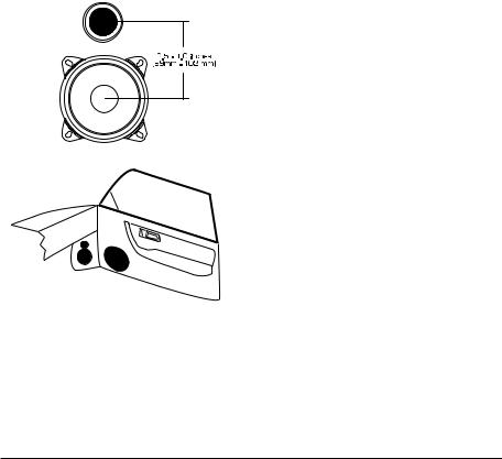
The XR653-CS system has been optimized for installations in which the midrange and tweeter drivers for each channel are mounted as close together as possible on the same mounting plane (such as a kick panel installation).This type of mounting will result in the best tonal balance and most coherent imaging.The center to center separation of the midrange and tweeter should be between 3.5 inches (89mm) and 4 inches (102mm) Any separation greater than 4 inches (102mm) from center to center of each driver is likely to result in degraded sound quality. We do not recommend mounting the tweeters in a different location than the midrange driver (for example: tweeters on the dash, midrange in the door).
Avoid placing tweeters where they will be blocked by objects in the interior of the car (including seated occupants). When selecting a mounting location, look at both sides of the car to make sure that this location is clear on both sides.
The 6.5 inch (160mm) woofers will usually be placed into factory speaker locations and can be separated from the midrange and tweeter by as much as 18 inches (46 cm), without degrading sound quality. For proper low-frequency performance, the woofers need a fairly large air space behind them (like the air inside of a door). Enclosing the XR650-CW woofers in spaces smaller than 1 cu.ft (28 liters) is not recommended if optimum low-frequency and midbass performance is desired.
We do not recommend mounting the woofer and midrange into the same enclosed environment, as this will cause energy from the woofer to modulate the midrange driver, resulting in distortion and coloration of the sound. If you are mounting the mids and woofers into the same environment, you will need to sub-enclose the midrange speakers in an enclosure with a minimum of 0.08 cu.ft. (2.3 liters).This guideline also applies to any other enclosed application of the midrange driver:
Enclosures smaller than 0.08 cu.ft (2.3 liters) will alter the frequency response of the midrange driver and result in degraded sound quality.
INSTALLING THE WOOFERS IN
FACTORY LOCATIONS:
If you will be using the factory speaker wires, it may be necessary to change the terminations. This may be accomplished by using an adaptor plug or simply by cutting the factory connector off and using the supplied crimp connectors to terminate the speaker wires.The large connector is for the positive terminal and the small connector is for the negative terminal of each woofer. Keep in mind that the woofer wires must be connected to the woofer outputs of the crossovers supplied with your system as shown in the diagram on page 3. You may also choose to run new speaker wires...refer to the custom installation section for details. Whichever method you choose, observe correct polarity in your connections. If you are unsure about any of these issues, contact your authorized JL AUDIO dealer for installation assistance.
4 |
JL AUDIO XR653-CS |
 Loading...