


owner’s manual
600W Monoblock Subwoofer Amplifier
Thank you for purchasing a JL Audio amplifier for your automotive sound system.
Your amplifier has been designed and manufactured to exacting standards in order to ensure years of musical enjoyment in your vehicle. For maximum performance, we highly recommend that you have your new amplifier installed by an authorized JL Audio dealer. Your authorized dealer has the training, expertise and installation equipment to ensure optimum performance from this product. Should you
decide to install the amplifier yourself, please take the time to read this manual thoroughly so as to familiarize yourself with its installation requirements and setup procedures.
If you have any questions regarding the instructions in this manual or any aspect of your amplifier’s operation, please contact your authorized JL Audio dealer for assistance. If you need further assistance,
please call the JL Audio Technical Support Department at (954) 443-1100 during business hours.

Protect Your Hearing!
We value you as a long-term customer. For that reason, we urge you to practice restraint in the operation of this product so as not to damage your hearing and that of others in your vehicle. Studies have shown that continuous exposure to high sound pressure levels can lead to permanent (irreparable) hearing loss. This and all other high-power amplifiers are capable of producing such high sound pressure levels when connected to a speaker system. Please limit your continuous exposure to high volume levels.
While driving, operate your audio system in a manner that still allows you to hear necessary noises to operate your vehicle safely (horns, sirens, etc.).
Serial Number
In the event that your amplifier requires service or is ever stolen, you will need to have a record of the product’s serial number. Please take the time to enter that number in the space
provided below. The serial number can be found on the bottom panel of the amplifier and on the amplifier packaging.
Serial Number:
Installation Applications
This amplifier is designed for operation in vehicles with 12 volt, negative-ground electrical systems. Use of this product in vehicles with positive ground and/or voltages other than 12V may result in damage to the product and will void the warranty.
This product is not certified or approved for use in aircraft.
Do not attempt to “bridge” the outputs of this amplifier with the outputs of a second amplifier, including an identical one.
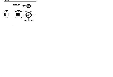
Infrasonic |
|
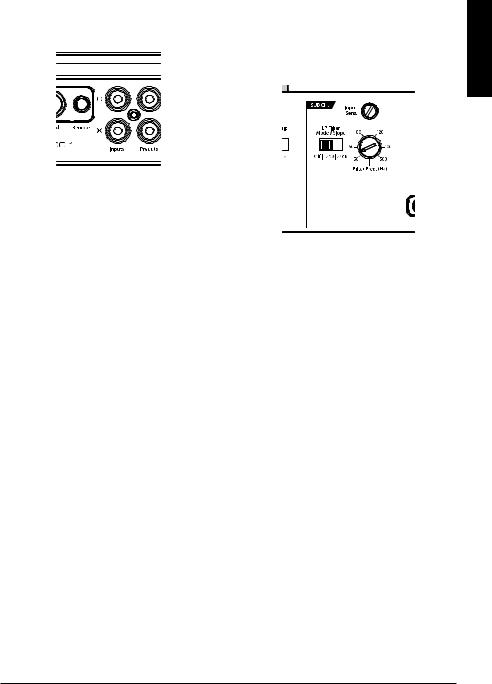
LP Filter |
Filter |
Filter |
Status |
Mode/Slope |
Frequency |
Selection |
LED |
Selection |
Selector |
(pg. 9) |
(pg. 11) |
(pg. 8) |
(pg. 8) |
Input Sensitivity
Control
(pg. 7)
2 | JL Audio - XD600/1 Owner’s Manual
Planning Your Installation
It is important that you take the time to read this manual and that you plan out your installation carefully. The following are some considerations that you must take into account when planning your installation.
Cooling Efficiency Considerations:
The outer shell of your JL Audio amplifier is designed to remove heat from the amplifier circuitry. For optimum cooling performance, this outer shell should be exposed to as large a
volume of air as possible. Enclosing the amplifier in a small, poorly ventilated chamber can
lead to excessive heat build-up and degraded performance. If an installation calls for an enclosure around the amplifier, we recommend that this enclosure be ventilated with the aid of a fan. In normal applications, fan-cooling
is not necessary.
Mounting the amplifier upside down is strongly discouraged.
If mounting the amplifier under a seat, make sure there is at least 1 inch (2.5 cm) of space above the amplifier’s outer shell to permit proper cooling.
Safety Considerations:
Your amplifier needs to be installed in a dry, well-ventilated environment and in a manner which does not interfere with your vehicle’s safety equipment (air bags, seat belt systems, ABS brake systems, etc.). You should also take the time to securely mount the amplifier so that it does not come loose in the event of a collision or a sudden jolt to the vehicle.
Stupid Mistakes to Avoid
•Check before drilling any holes in your vehicle to make sure that you will not be drilling through a gas tank, brake line, wiring harness or other vital vehicle system.
•Do not run system wiring outside or underneath the vehicle. This is an extremely dangerous practice which can result in severe damage to your vehicle and person.
•Protect all system wires from sharp metal edges and wear by carefully routing them, tying them down and using grommets and loom where appropriate.
•Do not mount the amplifier in the engine compartment, under the vehicle, on the roof or in any other area that will expose the amplifier circuitry to the elements.
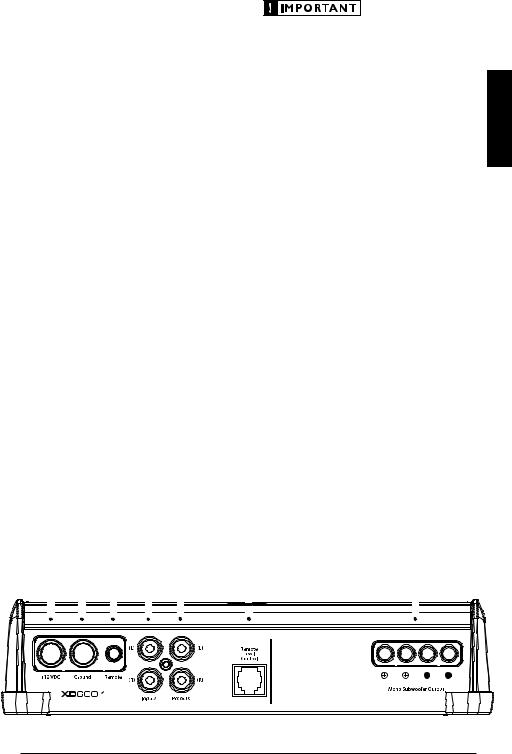
|
|
|
Chassis Ground |
Left & Right |
|
|
|
|
|
|
|
|
||||||||||||||
|
|
|
Connector |
|
|
|
Preamp Input Jacks |
|
|
|
|
|
|
|
|
|||||||||||
|
|
|
|
(pg. 5) |
|
|
|
|
(pg. 7) |
Jack for |
|
|
|
|
||||||||||||
+12 V Power |
|
|
|
Remote Turn-On |
|
|
Left & Right |
Remote Level |
Mono |
|||||||||||||||||
Connector |
|
|
|
|
Connector |
|
|
Preamp Output Jacks |
Control Knob |
Subwoofer Outputs |
||||||||||||||||
(pg. 5) |
|
|
|
|
(pg. 6) |
|
|
|
(pg. 10) |
(pg. 9) |
(pg. 10) |
|||||||||||||||
|
|
|
|
|
|
|
|
|
|
|
|
|
|
|
|
|
|
|
|
|
|
|
|
|
|
|
|
|
|
|
|
|
|
|
|
|
|
|
|
|
|
|
|
|
|
|
|
|
|
|
|
|
|
|
|
|
|
|
|
|
|
|
|
|
|
|
|
|
|
|
|
|
|
|
|
|
|
|
|
|
3
ENGLISH

Product Description
The XD600/1 is a monoblock amplifier utilizing JL Audio NexD™ high speed switching technology to deliver outstanding fidelity and efficiency.
The XD600/1 can be operated with a wide variety of source units and system configurations.
Its frequency response is limited to the range below 500 Hz. It is not designed for driving midrange speakers or tweeters. Every aspect of its operation has been optimized for low-frequency amplification. For detailed specifications, please refer to Appendix C (page 13).
Typical Installation Sequence
The following represents the sequence for a typical amplifier installation, using an aftermarket source unit or OEM Interface processor (like the CleanSweep CL441dsp).
Additional steps and different procedures may be required in some applications. If you have any questions, please contact your authorized JL Audio dealer for assistance.
1) Disconnect the negative battery post connection and secure the disconnected cable to prevent accidental re-connection during installation. This step is not optional.
2) Run 4 AWG power wire from the battery location to the amplifier mounting location, taking care to route it in such a way that it will not be damaged and will not interfere with vehicle operation. Use 4 AWG or larger power wire and a power distribution block if additional amplifiers are being installed with the XD600/1.
3) Connect power wire to the positive battery post. Fuse the wire with an appropriate fuse block (and connectors) within 18 inches (45 cm) wire length of the positive battery post.
This fuse is essential to protect the vehicle. Do not install the fuse until the power wire has been securely connected to the amplifier.
4) Run signal cables and remote turn-on wire from the source unit to the final amplifier mounting location.
5) Run speaker cables from the speaker systems to the amplifier mounting location.
6) Find a good, solid metal grounding point close to the amplifier and connect the negative power wire to it using appropriate hardware (use of the JL Audio ECS master ground lug, XB-MGLU is recommended). Use 4 AWG wire, no longer than 36 inches (90 cm) from the amplifier to the ground connection point. In some vehicles, it may be necessary to upgrade the battery ground wire. (See page 5 for important notice).
7) Securely mount the amplifier.
8) Connect the positive and negative power wires to the amplifier. A fuse near
the amplifier is not necessary if the XD600/1 is the only device being run from the fused main power wire. If the fused main power wire is shared by the XD600/1 and other amplifiers or devices, fuse each amplifier/device
within 12 inches (30 cm) of wire length, via a fused distribution block or multiple individual fuse blocks/on-board fuses.
9) Connect the remote turn-on wire
to the amplifier.
10)Connect the input cables to the amplifier.
11)Connect the speaker cables to the amplifier.
12)Carefully review the amplifier’s control settings to make sure that they are set according to the needs of the system.
13)Install the power wire fuse (50A for a single XD600/1) and reconnect the negative battery post terminal. Install the fuse (50A) near the amplifier (if applicable).
14)Turn on the source unit at a low level to double-check that the amplifier is
configured correctly. Resist the temptation to crank it up until you have verified the control settings.
15) Make necessary adjustments to the input sensitivity controls to obtain the right overall output and the desired balance in the system. See Appendix A (page 12) for the recommended input sensitivity setting method.
16)Enjoy the fruits of your labor with your favorite music.
4 | JL Audio - XD600/1 Owner’s Manual

Power Connections
Before installing the amplifier, disconnect the negative (ground) wire from the vehicle’s battery. This will prevent accidental damage to the system, the vehicle and your body during installation.
The XD600/1’s “+12 VDC” and “Ground” connections are designed to accept 4 AWG power wire. 4 AWG is the required wire size for this amplifier.
If you are installing the XD600/1 with other amplifiers and wish to use a single main power wire, use 2 AWG or 1/0 AWG main power wire (depending on the overall current demands of all the amplifiers in the system). This 2 AWG or 1/0 AWG power wire should terminate into a fused distribution block mounted as close to
the amplifiers as possible (within 12 inches / 30cm of wire length). The fused output of the distribution block will connect to the XD600/1 with 4 AWG power wire. JL Audio ECS
fused distribution blocks are recommended (XD-FDBU-2 and XD-FDBU-4)
Note: Smaller AWG numbers mean bigger wire and vice-versa (1/0 AWG is the largest, 2 AWG is smaller, then 4 AWG, then 8 AWG, etc.).
To connect the power wires to the amplifier, first back out the set screw on the top of the terminal block, using the supplied 2.5 mm hex wrench. Strip 1/2 inch (12 mm) of insulation from the end of each wire and insert the bare wire into the terminal block, seating it firmly so that no bare wire is exposed. While holding the wire in place, tighten the set screw firmly, taking care not to strip the head of the screw.
The ground connection should be made using 4 AWG wire and should be kept as short as possible, while accessing a solid piece of sheet metal in the vehicle. The surface of the sheet metal should be sanded at the contact point
to create a clean, metal-to-metal connection between the chassis and the termination of the ground wire. For optimal grounding, we recommend the use of a JL Audio ECS master ground lug (XB-MGLU). Alternatively, a sheet metal screw or bolt can be used with a star washer.
Any wires run through metal barriers (such as firewalls), must be protected with a high quality rubber grommet to prevent damage to the insulation of the wire. Failure to do so may result in a dangerous short circuit.
Many vehicles employ small (10 AWG - 6 AWG) wire to ground the battery to the
vehicle chassis and to connect the alternator’s positive connection to the battery. To prevent voltage drops, these wires should be upgraded to 4 AWG when installing amplifier systems with main fuse ratings above 60A.
Fuse Requirements
It is absolutely vital that the main power wire(s) to the amplifier(s) in the system be fused within 18 inches (45 cm) of the positive battery post connection. The fuse value at each power wire should be high enough for all of the equipment being run from that power wire. If only the XD600/1 is being run from that power wire, use a 50A fuse.
If fusing the amplifier near its power connections (when more than one amp is being run from the main power wire), use a 50A fuse (MAXI™ big plastic-body fuse is recommended).
ENGLISH
5
Turn-On Lead
The XD600/1 uses a conventional +12V remote turn-on lead, typically controlled by the source unit's remote turn-on output. The amplifier will turn on when +12V is present at its “Remote” input and turn off when +12V is switched off. If a source unit does not have a dedicated remote turn-on output, the amplifier’s turn-on lead can be connected to +12V via a switch that derives power from an ignition-switched circuit.
The XD600/1’s “Remote” turn-on connector is designed to accept 18 AWG – 12 AWG wire. To connect the remote turn-on wire to the amplifier, first back out the set screw on the top of the terminal block, using the supplied 2.5 mm hex wrench. Strip 1/2 inch (12mm) of wire and insert the bare wire into the terminal block, seating it firmly so that no bare wire is exposed. While holding the wire in the terminal, tighten the set screw firmly, taking care not to strip the head of the screw and making sure that the wire is firmly gripped by the set screw.
6 | JL Audio - XD600/1 Owner’s Manual
Input Section
The XD600/1’s input section allows you to send signal to the amplifier section through the use of two differentialbalanced inputs, one for the left channel signal and one for the right channel signal. Connection is via RCA-type jacks.
You may run a stereo or a mono signal into the inputs of the amplifier. The amplifier’s input section automatically sums stereo signals to mono for the internal amplifier section. The amplifier will operate with only one input connection (left or right), but will require an increase in input sensitivity to overcome the loss of signal. If a mono input signal is to be run, we recommend that you use a “Y-adaptor” to split the mono signal into both inputs of the amplifier.
Input Voltage Range:
The XD600/1’s input section is designed to accept signal voltages from 100mV – 4V. This will accommodate all preamp level signals and many speaker level signals.
To use speaker-level sources, simply splice the speaker output wires of the source unit onto a pair of RCA plugs for each input pair. (or use
JL Audio part XD-CLRAIC2-SW) No “line output converter” is needed in most cases.
If you find that the output cannot be reduced sufficiently with a direct speaker level signal applied to the amplifier, you may use a “line output converter” or voltage divider to reduce the signal level.
Input Sensitivity Controls
The control labeled “Input Sens.” can be used to match the source unit’s output voltage to the input stage the XD600/1 for maximum clean output. Rotating the control clockwise will result in higher sensitivity (louder for a given input voltage). Rotating the control counter-clockwise will result in lower sensitivity (quieter for a given input voltage.)
To properly set the amplifier for maximum clean output, please refer to Appendix A (page 12) in this manual. After using this procedure, you can then adjust the “Input Sens.” levels downward if this is required to achieve the desired system balance.
Do not increase any “Input Sens.” setting for any channel(s) of any amplifier in the system beyond the maximum level established during the procedure outlined in Appendix A (page 12). Doing so will result in audible distortion and possible speaker damage.
ENGLISH
7
Filter Controls
Most speakers are not designed to reproduce the full range of frequencies audible by the human ear. For this reason, most speaker systems are comprised of multiple speakers, each dedicated to reproducing a specific frequency range. Filters are used to select which frequency range is sent to each section of a speaker system. The division of frequency ranges to different speakers can be done with passive filters (coils and/or capacitors between the amplifier outputs and the speakers), which are acceptable and commonly used
for filtering between mid-range speakers and tweeters. Filtering between subwoofer systems and satellite speaker systems is best done with active filters, which cut off frequency content at the input to the amplifier. Active filters are more stable than passive filters and do not introduce extraneous resistance, which can degrade subwoofer performance.
The active low-pass filter built into the XD600/1 is designed to attenuate frequencies above its filter frequency, so that the system’s subwoofers do not
reproduce any audible midrange content. This serves to improve tonal balance
and to avoid distortion. Correct use of the filter can substantially improve the fidelity of your audio system.
2)LP Filter Operation: The low-pass filter in the XD600/1 is fully variable between 50 Hz and 500 Hz via the “Filter Freq.” control knob and
features the ability to select between a moderate “12dB” per octave or a steep “24dB” per octave slope via the “LP Filter Mode/Slope” switch.
Depending on the subwoofer system and the vehicle, different slopes may be required to produce a smooth transition to the midbass speakers in the system. Experiment to find the slope which best matches the acoustic requirements of your system.
Tuning Hint: A trunk mounted sub whose output has to “fight” through a rear deck or a back seat often benefits from the 12 dB/octave slope which lets more upper bass content pass through. A sub that fires directly into the listening environment is more likely to benefit from a 24 dB/octave slope.
Note: The above hint is not “set-in-stone”…
You should always listen to the system carefully to determine the best choice as vehicle acoustics and other factors play a big role in choosing the most appropriate filter slope.
3)Precise Frequency Selection: The filter frequency markings on the front panel of the amplifier are for reference purposes and are generally accurate to within 1/3 octave or better. If you would like to select the filter frequency with a higher level of precision, consult Appendix B (page 13) of this manual.
This chart gives you a more accurate frequency for each of the forty detented positions of the frequency selection control. This method can be very useful if the amplifier is mounted in
a location where you can’t see the front panel markings easily.
4)Defeating the LP Filter: The Low-Pass filter can also be defeated completely, by switching the “LP Filter Mode/Slope” switch to the “Off” position. This is useful if you are using an external active crossover in the system. With the internal crossover turned off, the XD600/1’s upper frequency response limit is 500 Hz, due to its subwoofer-specific design.
8 | JL Audio - XD600/1 Owner’s Manual

INFRASONIC FILTER
The “Infrasonic Filter” is a 24 dB/octave highpass filter, with a fixed cutoff frequency of 30 Hz. This filter is designed to conserve amplifier power and protect subwoofer systems, without audibly degrading the sub-bass output.
With ported enclosures, the use of the “Infrasonic Filter” is highly recommended to protect the speaker(s) from excessive excursion below box tuning.
With sealed enclosures, the use of the filter is less necessary, but can still help protect the speaker system from excessive excursion.
The “Infrasonic Filter” can be completely defeated by selecting the “Off” position on its switch. This bypasses all signal from flowing through the circuit.
Remote Level control (Optional)
With the addition of the optional Remote Level Control (HD-RLC), you can control the subwoofer volume from the front of the vehicle. The HD-RLC connects to the jack labeled “Remote Level Control” on the Connection Panel of the amplifier using a standard telephone cable (supplied with the HD-RLC). If desired, multiple XD (and HD) amplifiers can be controlled from a single HD-RLC controller using a simple phone
line “splitter” and multiple phone cables. When connected to the amplifier, the
HD-RLC operates as follows. At full counterclockwise rotation, the audio will mute completely. At full clockwise rotation the level will be the same as if the HD-RLC was not connected at all. In other words, it operates strictly as a level attenuator.
ENGLISH
9
PreOUTS
The XD600/1 incorporates a pass-through preamp output section, so that additional amplifiers can be easily added to the system. The preamp output delivers the same signal that is connected to the XD600/1’s inputs.
The preamp output signal by any crossover filter selected (if the input signal is full-range, the preamp output will be full-range).
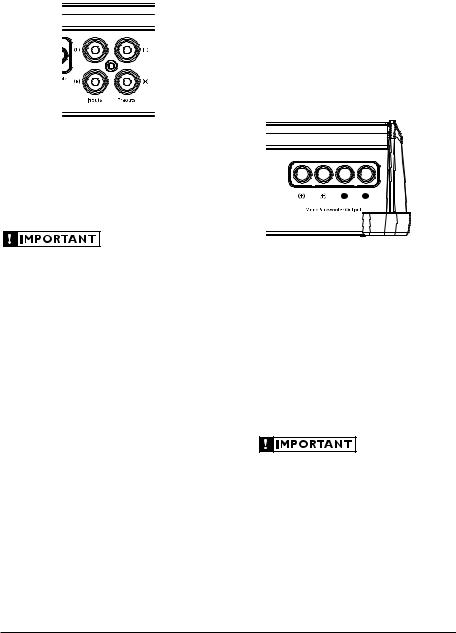
SUBWOOFER OUTPUTS
The XD600/1 is designed to deliver power into subwoofer loads equal to or greater than 2 ohms.
The XD600/1’s subwoofer outputs are designed to accept 16 AWG - 8 AWG wire. To connect the subwoofer wires to the amplifier, first back out the set screws on the top of the terminal block, using the supplied 2.5 mm hex wrench. Strip 1/2 inch (12 mm) of insulation from the end of each wire and insert the bare wire into the terminal block, seating it firmly so that no bare wire is exposed. While holding the wire in place, tighten the set screw firmly, taking care not to strip the head of the screw.
If you plan to use the “Preouts” to feed a stereo amplifier, you must connect a
stereo signal to the input of the amplifier. A mono signal into the amplifier will result in a mono signal out of the preamp output.
You will notice that there are two “+” positive connections and two “–” negative connections. This is to facilitate multiple subwoofer wiring.
The two positive and two negative connections are connected in parallel inside the amplifier They are not stereo outputs. Connecting two subwoofers, each to one set of positive and negative terminals, will result in a parallel subwoofer connection. If only connecting one pair of subwoofer wires, it is not necessary to use both sets of connections.
Subwoofer loads below 2 ohms nominal are not recommended and may cause the amplifier
to initiate a protection mode which reduces power output.
10 | JL Audio - XD600/1 Owner’s Manual
Status LED / Protection Circuitry
There is a single multi-color LED on the top surface of the amplifier to indicate the amplifier’s operating status.
1)Flashing Green: amplifier is powering up, audio output is muted.
2)Constant Green: amplifier is on and functioning normally, audio output is active.
3)Constant Red: lights to indicate that the amplifier has exceeded its safe operating temperature, putting the amplifier into a self-protection mode, which reduces the peak power output of the amplifier. When its temperature returns to a safe level, the red
light will return to green and the amplifier will return to full-power operating mode.
4)Constant Amber (yellow): Indicates
that an over-current condition has occurred and is accompanied by a muting of the amplifier’s output. Because the muting behavior may be very short in duration, it may manifest itself as an audible, repetitive ticking or thumping noise in the output. Over-current conditions can be caused by a speaker impedance lower than the optimum load impedance range for the amplifier or a short-circuit in the speaker wiring. The latter can result from a short circuit between the positive and negative speaker wires or between either speaker wire and the vehicle chassis.
The “Status LED” will remain amber for a few seconds, even if the over-current condition is of a very short duration.
5) LED off / Amplifier Shuts Off Unexpectedly
The only condition that will shut down
an undamaged XD600/1 completely is if battery voltage or remote turn-on voltage drops below 10 volts. The “Status LED” will turn off when this occurs. The amplifier will turn back on when voltage climbs back above 11 volts. If this is happening in your system, have your charging system and power wiring inspected.
For more information on troubleshooting this amplifier, refer to Appendix D (pages 14, 15).
Servicing your JL Audio Amplifier
If your amplifier fails or malfunctions, please return it to your authorized JL Audio dealer so that it may be sent in to JL Audio for service. There are no user serviceable parts or fuses inside the amplifier. The unique nature of the circuitry in the JL Audio amplifiers requires specifically trained service personnel. Do not attempt
to service the amplifier yourself or through unauthorized repair facilities. This will not only void the warranty, but may result in the creation of more problems within the amplifier.
If you have any questions about the installation or setup of the amplifier not covered in this manual, please contact your dealer or technical support.
JL Audio Technical Support: (954) 443-1100
9:00 AM – 5:30 PM (Eastern Time Zone) Monday - Friday
ENGLISH
11
 Loading...