

Thank you for choosing JL Audio Evolution XR Coaxials for your
automotive sound system. With proper installation, your new
speakers will deliver years of listening pleasure.
We strongly recommend that you have your new Evolution speakers
installed by your authorized JL Audio dealer. The installation
professionals employed by your dealer have the necessary tools and
experience to disassemble your interior panels, install your new
speakers and reassemble your vehicle properly. Also, keep in mind
that your warranty coverage extends to 1 year if your system is
installed or approved by your authorized JL Audio dealer. If you
prefer to perform your own installation, please read this instruction
manual completely before beginning the process.
XR650-CXi
6.50-inch (160 mm) Coaxial Speaker System
owner’s manual
XR650-CXi SPECIFICATIONS:
Woofers: Mineral-filled polypropylene cone body,
1-inch (25mm) voice coil, low-profile/symmetricalroll spider, butyl rubber surround.
Tweeters:1-inch (25 mm) aluminum dome
tweeter with rubber surround, neodymium
magnet, ferrofluid cooled and damped.
Adjustable tweeter angle.
Crossover Networks: 2-way network with 1st
order low-pass circuit and 2nd order high pass
circuit. Premium Mylar Capacitors and Air-Core
inductors. 3-position adjustable tweeter output
level. 3-position midrange presence control.
Polyswitch™ tweeter protection.
Continuous Power Handling:
70 Watts (RMS Method)
Frequency Response: 48 Hz - 25 KHz (± 3 dB)
Efficiency @ 1W/1m: 89.5 dB
Nominal Impedance: 4 ohms
Included Components and Parts:
• Two XR650-CXi 6.50-inch (160 mm)
Coaxial Speakers
• Two XR650-CXpxo 2-Way Crossover Networks
• Two Metal Woofer Grilles and Grille Trays
• Butyl Adhesive Putty for woofer grilles
• Twelve #8 x 1 1/4 inch (30 mm)
Sheet Metal Screws
• Eight Mounting Clips
• Twelve Crimpable Fork Terminals
• Four Black Nylon Wire Ties
• Four 5-ft. (1.5 m) lengths of paired
speaker wire with female clips
GETTING STARTED:
• Turn off the audio system. It is also advisable
to disconnect the negative (-) terminal of
your vehicle’s battery whenever performing
installation work.
• Before cutting, drilling or inserting any screw,
check clearances on both sides of the planned
mounting surface. Also check for any potential
obstacles, such as window tracks and motors,
wiring harnesses, etc. Check both sides of the car,
many cars are not symmetrical!
• Always wear protective eyewear.
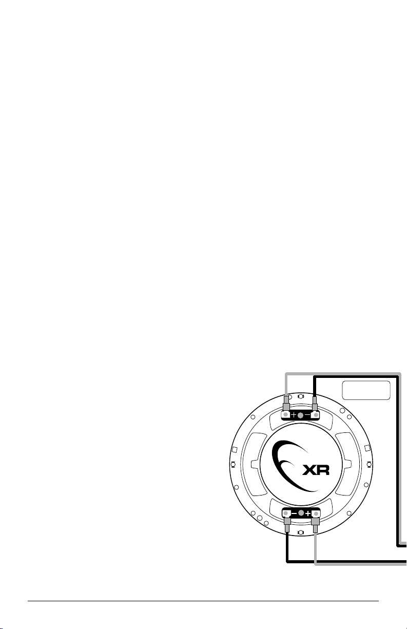
WARNING!
It is absolutely vital that your component
system is connected as shown in Diagram A
below. Failure to connect the system as shown
will result in damage to your speakers which is
NOT covered under warranty. Do not
substitute different crossover networks into
your XR650-CXi System. Only use crossover
networks clearly marked “XR650-CXpxo”.
2 JL AUDIO XR650-CXi
large terminal: (+)
small terminal: (–)
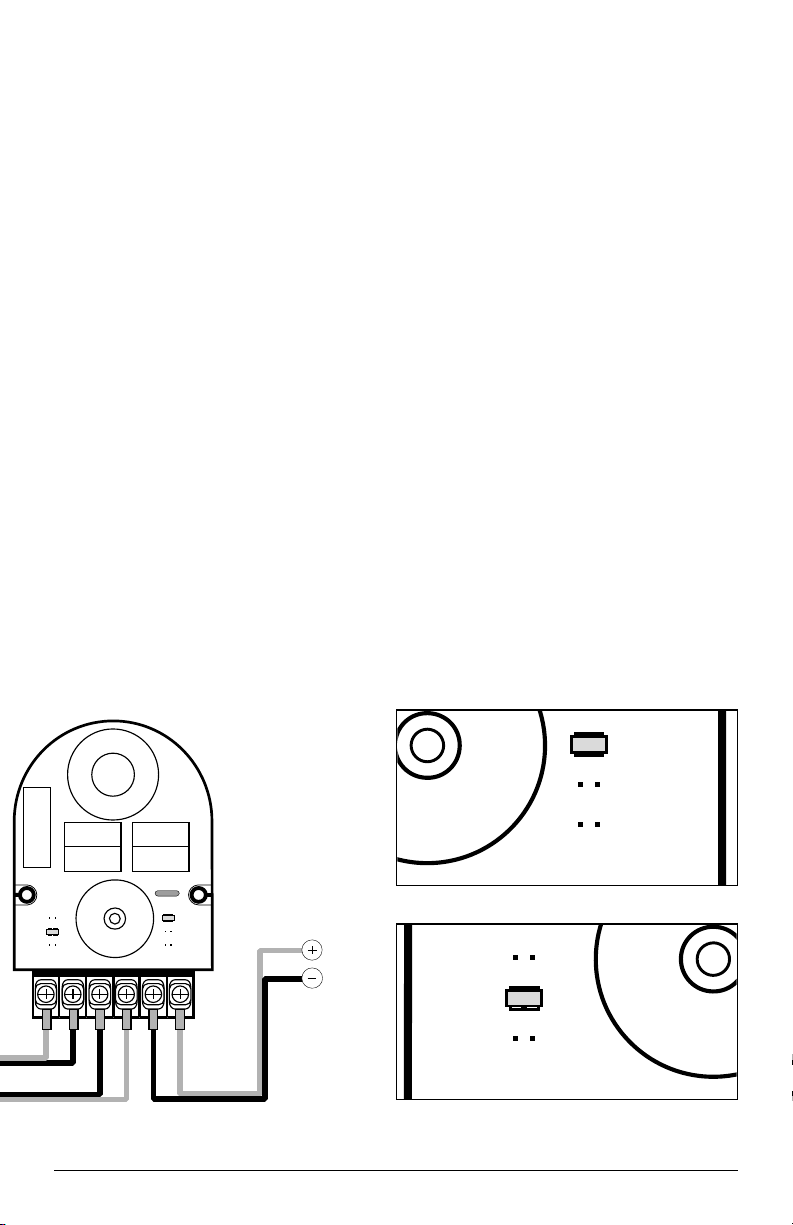
A) Wiring Diagram:
BUILT-IN TWEETER
PROTECTION CIRCUITRY:
The XR Crossover networks are equipped with
an advanced electronic tweeter protection circuit
designed to minimize the possibility of tweeter
failure. This electronic device monitors current going
to the tweeter and will disconnect the tweeter from
the signal when it senses overload. Should this occur
while listening to the audio system, simply reduce the
volume for a few seconds and the protection circuit
will reset itself automatically.
ADJUSTABLE TWEETER LEVEL:
Your XR Crossover networks provide three
levels of tweeter adjustability designed to
compensate for different mounting locations, vehicle
interiors and personal taste (see Diagram B).
These levels are selectable via a set of pins located
under the clear cover of each crossover case. We
recommend that you begin listening at the “REF”
(Reference) position. If the sound seems too bright
or aggressive, experiment with alternate tweeter
level settings by moving the jumper connectors. It is
safe to switch jumpers while the system is playing.
ADJUSTABLE MIDRANGE PRESENCE:
Your XR crossover networks also provide a
unique midrange presence control, located under
the clear cover (see Diagram C). The midrange
presence is selectable via a set of pins and allows for
three settings:“High-Mid”,“Normal” and “Low-Mid”.
The settings affect the overall amplitude of the
upper midrange response of the XR woofer
element.We recommend that you begin your
listening with the “Normal” setting and adjust up or
down as needed to compensate for mounting
location or personal taste.
SPEAKER PLACEMENT
CONSIDERATIONS:
In most cases, your speakers will be placed into
factory speaker locations. If you have some speaker
mounting flexibility, keep the following in mind:
Lower mounting locations, such as the lower
front corner of a door or a kick-panel provide the
greatest path length distances for the sound emitted
by the speakers. For this reason, they are generally
more desirable than higher mounting locations.
Higher mounting locations will usually result in
extreme near-side soundstage bias which
compromises the stereo listening experience.
JL AUDIO XR650-CXi 3
HIGH MID
NORMAL
LOW MID
REF
-1.5dB
-3.0dB
B) Adjustable Tweeter Level
C) Adjustable Midrange Presence
HIGH MID
NORMAL
LOW MID
T- W- W+ IN- IN+T+
JL AUDIO
XR650
CXpxo
JL AUDIO
Mylar
®
Capacitor
4.00 µF
REF
-1.5dB
-3.0dB
Amplifier
Output

INSTALLING YOUR XR650-CXi
COAXIALS IN FACTORY LOCATIONS:
Run the supplied speaker wires to the desired
mounting location. If you are running wires into a
door, use existing factory wiring boots whenever
possible. If you are drilling new holes, file their
edges and install rubber grommets into each hole.
Then, cover the wires with a protective PVC sleeve
and run them through the door jamb. Make sure
that the wires will clear door hinges and other
structures in the door. If you are unsure about any
part of this process, please contact your JL AUDIO
dealer for installation help.
Your new speakers have been designed to
install, without modifications, into most vehicles that
accept a 6.50-inch (160 mm) speaker. Most factory
6.50-inch speakers use four mounting screws which
will line up with the mounting holes on your
woofers. Multiple sets of mounting holes are
available to accommodate different vehicles’
factory hole patterns/orientations.
Connect the speaker wires to both sets of
terminals on each speaker, observing correct
polarity and making sure that the tweeter and
woofer wires correspond to the correct terminals
on both the speaker and crossover.
It is absolutely vital that the speaker frame fits
into the mounting hole cleanly. This must be
checked prior to tightening the screws. Do not
force the frame into a hole that is too small! Do
not tighten the speaker onto an uneven surface! This
will damage your speakers. The speaker should also
fit so that no air leaks around the mounting flange.
Air leaks will cause a severe degradation in sound
quality. Seal any air leaks with silicone, rope caulk or
similar sealant material.
Install as shown in the diagram below.Use the
supplied mounting clips unless the factory holes
already feature threaded inserts. Hand-tighten the
screws evenly to avoid bending the speaker frame!
4 JL AUDIO XR650-CXi

INSTALLING YOUR XR650-CXi
COAXIALS IN CUSTOM LOCATIONS:
Run the supplied speaker wires to the desired
mounting location. If you are running wires into a
door, use existing factory wiring boots whenever
possible. If you are drilling new holes, file their
edges and install rubber grommets into each hole.
Then, cover the wires with a protective PVC sleeve
and run them through the door jamb. Make sure
that the wires will clear door hinges and other
structures in the door. If you are unsure about any
part of this process, please contact your JL AUDIO
dealer for installation help.
Double check the clearance for both speakers
before proceeding.
Use the template supplied in the product
packaging to mark the desired mounting location. Be
aware that two different templates are supplied: one
for the XR525-CXi 5.25-inch (130 mm) coaxial and
one for the XR650-CXi 6.5-inch (160 mm) coaxial.
Use only the appropriate template! Mark the center
and the outline of the mounting hole as well as the
mounting screw positions. Before drilling or cutting,
use a utility knife to cut any fabric, vinyl or leather
from hole locations. These materials can easily be
snagged by a drill or a saw, causing damage to the
panel and possible bodily injury.
Drill four 1/8” (3 mm) holes for the speaker’s
mounting screws at the positions you have marked.
Also drill a pilot hole in the center of the speaker
mounting hole at this time. Then, using a saber saw,
hole saw or nibbler, make the circular cut out for
the speaker. File any rough edges.
Insert the mounting clips with the flat side
towards the speaker as shown in the diagram.
Connect the speaker wires to both sets of
terminals on each speaker, observing correct
polarity and making sure that the tweeter and
woofer wires correspond to the correct
terminals on both the speaker and crossover.
Install the speaker and grille tray as shown in the
diagram below.
It is absolutely vital that the speaker frame fits
into the mounting hole cleanly. This must be
checked prior to tightening the screws. Do not
force the frame into a hole that is too small!
Do not tighten the speaker onto an uneven surface!
This will damage your speakers. The speaker should
also fit so that no air leaks around the mounting
flange. Air leaks will cause a severe degradation in
sound quality. Seal any air leaks with silicone, rope
caulk or similar sealant material.
Hand-tighten the screws evenly to avoid
bending the speaker frame!
Break off small pieces of the supplied butyl
adhesive putty and place them on the inside of each
grille tray. This adhesive will hold the grille in place
firmly and prevent rattling. Then inser t the metal
grille into the grille tray, squeezing gently around its
edge until it seats firmly into the tray.
JL AUDIO XR650-CXi 5

CROSSOVER NETWORK
INSTALLATION:
The crossover networks supplied with your
XR650-CXi System should be installed in a dry
location of your vehicle. DO NOT INSTALL
CROSSOVERS INSIDE OF A DOOR!
Doors often get wet on the inside, which can
damage your crossover networks and could
potentially damage your entire sound system.
The crossovers can be screwed into a solid
surface via two holes located under the protective
cover of the case. To access these holes, simply
squeeze the sides of the cover while gently pulling
the cover away from the base. Make sure that your
mounting location will not cause damage to wiring,
fuel lines, brake lines or any other vital component
of your vehicle. Once you have screwed the case in,
snap the protective cover back into place.
If screwing the crossovers networks in is not
possible, you can also run the supplied nylon wire
ties through the mounting holes to attach the
crossovers to a structure in your car. To do so, take
the covers off, attach the wire ties, and then snap
the covers back into place, lining the wire ties up
with the slots on the sides of the protective cover.
Make sure that you do not attach the crossovers to
a moving part or to any par t that may interfere with
pedal operation, gear shift operation, steering, or
airbag deployment.
For crossover network wiring instructions,
refer to the diagram on pages 2 & 3 of this manual.
6 JL AUDIO XR650-CXi

ADJUSTING THE TWEETER ANGLE:
The tweeters of your XR coaxials feature
adjustable aiming via a rotating tweeter bezel. This
allows you to optimize tweeter dispersion in your
vehicle after installation of your speakers. To adjust
the dispersion of the tweeters, simply rotate the
tweeter bezel clockwise or counter-clockwise.
WARNING!
The tweeter will rotate 45 degrees to either
side of the center position. Do not force the
tweeter beyond this limit of rotation or you may
damage its wiring.
JL AUDIO XR650-CXi 7

JL AUDIO LIMITED WARRANTY (USA)
Evolution Speaker Systems
JL AUDIO warrants these speakers (and crossover networks, where applicable) to be free of defects in
materials and workmanship for a period of ninety (90) days from the original date of purchase. The warranty
term is extended to one (1) year if installation is performed or approved by an authorized JL AUDIO dealer
(proof of installation or approval required on purchase receipt).
This warranty is not transferrable and applies only to the original purchaser from an authorized JL AUDIO
dealer. Should service be necessar y under this warranty for any reason due to manufacturing defect or
malfunction, JL AUDIO will, at its discretion, repair or replace the defective product with new or remanufactured
product at no charge.
Damage caused by the following is not covered under warranty: accident, misuse, abuse, product modification
or neglect, failure to follow installation instructions, unauthorized repair attempts, misrepresentations by the seller.
This warranty does not cover incidental or consequential damages and does not cover the cost of removing or
reinstalling the unit(s). Cosmetic damage due to accident or normal wear and tear is not covered under warranty.
Any applicable implied warranties are limited in duration to the period of the express warranty as provided
herein beginning with the date of the original purchase at retail, and no warranties, whether express or implied,
shall apply to this product thereafter. Some states do not allow limitations on implied warranties, therefore these
exclusions may not apply to you. This warranty gives you specific legal rights, and you may also have other rights
which vary from state to state.
If you need service on your JL AUDIO product:
All warranty returns should be sent to JL AUDIO freight prepaid through an authorized
JL AUDIO dealer and must be accompanied by proof of purchase (a copy of the original sales receipt.) Direct
returns from consumers or non-authorized dealers will be refused unless specifically authorized by JL AUDIO
with a valid return authorization number. Warranty expiration on products returned without proof of purchase
will be determined from the manufacturing date code. Coverage may be invalidated as this date is previous to
purchase date. Return only defective components. If one speaker fails in a system, return only that speaker
component, not the entire system. Non-defective items received will be returned freight-collect. Customer is
responsible for shipping charges and insurance in sending the product to JL AUDIO. Freight damage on returns
is not covered under warranty.
For Service Information in the U.S.A. please call:
JL Audio customer service: (954)443-1100
during normal business hours (Eastern Time)
JL Audio, Inc
10369 North Commerce Pkwy.
Miramar, FL 33025
(do not send product for repair to this address)
International Warranties:
Products purchased outside the United States of America are covered only
by that country’s distributor and not by JL Audio, Inc.
Printed in USA JLXR650CXi-02-2003
 Loading...