

JL Audio XD300, XD301 Owner's Manual
Thank you for purchasing a JL Audio amplifier for
your automotive sound system.
Your amplifier has been designed and manufactured to exacting
standards in order to ensure years of musical enjoyment in your vehicle.
For maximum performance, we highly recommend that you have
your new amplifier installed by an authorized JL Audio dealer. Your
authorized dealer has the training, expertise and installation equipment
to ensure optimum performance from this product. Should you
decide to install the amplifier yourself, please take the time
to read this manual thoroughly so as to familiarize yourself
with its installation requirements and setup procedures.
If you have any questions regarding the instructions in this
manual or any aspect of your amplifier’s operation, please contact your
authorized JL Audio dealer for assistance. If you need further assistance,
please call the JL Audio Technical Support Department
at (954) 443-1100 during business hours.
OWNER’S MANUAL
300W Monoblock Subwoofer Amplier
2 | JL Audio - XD300/1 Owner’s Manual
3
ENGLISH
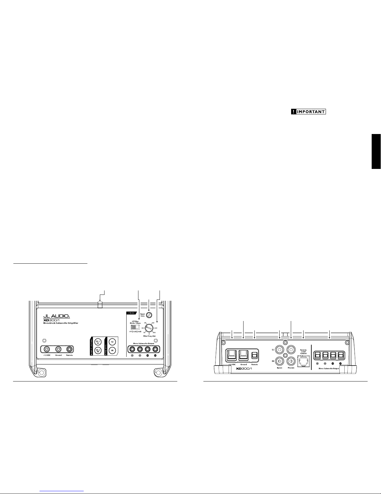
Status
LED
(pg. 11)
Filter
Frequency
Selector
(pg. 8)
LP Filter
Mode/Slope
Selection
(pg. 8)
Input Sensitivity
Control
(pg. 7)
PLANNING YOUR INSTALLATION
It is important that you ta ke the time to read
this manual and t hat you plan out your
installation carefully. The following are some
considerations that you must take into account
when planning your installation.
Cooling Efficiency Considerations:
The outer shell of your JL Audio amplifier
is designed to remove heat from the amplif ier
circuitry. For optimum cooling performance,
this outer shell should be exposed to as large a
volume of air as possible. Enclosing the amplif ier
in a small, poorly venti lated chamber can
lead to excessive heat build-up a nd degraded
performa nce. If an instal lation calls for an
enclosure around the amplifier, we recommend
that this enclosure be ventilated with the aid
of a fan. In normal applications, fan-cooling
is not necessary.
Mounting the amplifier upside down is
strongly discouraged.
If mounting the ampli fier under a seat,
make sure t here is at least 1 inch (2.5 cm) of
space above the amplif ier’s outer shell to permit
proper cooling.
Safety Considerations:
Your amplifier needs to be installed in a dry,
well-ventilated environment and in a manner
which does not i nterfere wit h your vehicle’s safety
equipment (air bags , seat belt systems, ABS brake
systems, etc.). You should also take the time to
securely mou nt the amplifier so t hat it does not
come loose in t he event of a collision or a sudden
jolt to the vehicle.
Stupid Mistakes to Avoid
• Check before dril ling any holes in your vehicle
to make sure that you will not be drilling
through a gas tank, brake line, wiring harness or
other vital vehicle system.
• Do not run system wiring out side or underneath
the vehicle. This is an extremely dangerous
practice which can result in severe damage to
your vehicle and person.
• Protect all system wires from sharp metal
edges and wear by caref ully routing them,
tying them down and using grommets and
loom where appropriate.
• Do not mount t he amplifier in t he engine
compart ment, under the vehicle, on the roof
or in any other area that w ill expose the
amplif ier circuitry to the elements.
PROTEC T YOUR HE ARING!
We value you as a long-term cu stomer. For
that reason, we urge you to practice restraint in
the operation of this product so as not to da mage
your hearing and that of others in your vehicle.
Studies have shown that continuous exposure to
high sound pressure levels can lead to permanent
(irreparable) hearing loss. This a nd all other
high-power amplifiers are capable of producing
such high sound pressure levels when connected
to a speaker system. Please li mit your continuous
exposure to high volume levels.
While d riving, operate your audio system in
a manner that stil l allows you to hear necessary
noises to operate your vehicle safely (horns,
sirens, etc.).
SERIAL NUMBER
In the event that your amplifier requires
service or is ever stolen, you will need to have
a record of the product’s seria l number. Please
take the time to enter t hat number in the space
provided below. The serial number can be fou nd
on the bottom panel of the amplifier and on the
amplifier packaging.
Serial Number:
INSTALLATION APPLICATIONS
This ampl ifier is designed for operation in
vehicles with 12 volt, negat ive-ground electrical
systems. Use of this produc t in vehicles with
positive ground and/or voltages other than 12V
may result in d amage to the product and w ill void
th e war rant y.
This product is not certified or approved for
use in aircraft.
Do not attempt to “bridge” the outputs of this
amplif ier with the outputs of a second amplifier,
including an identica l one.
Remote Turn-On
Connector
(pg. 6)
Chassis Ground
Connector
(pg. 5)
Left & Right
Preamp Output Jacks
(pg. 10)
+12 V Power
Connector
(pg. 5)
Mono
Subwoofer Outputs
(pg. 10)
Jack for
Remote Level
Control Knob
(pg. 9)
Left & Right Preamp
Input Jacks
(pg. 7)

4 | JL Audio - XD300/1 Owner’s Manual
5
ENGLISH
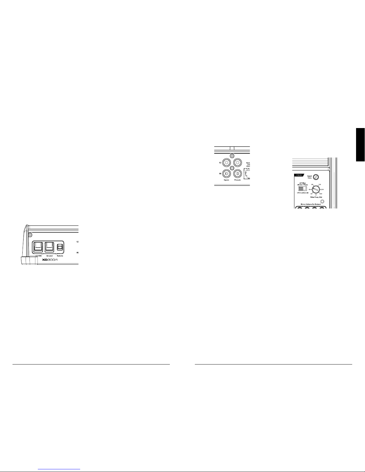
POWER CONNECTIONS
Before installi ng the amplifier, disconnect t he
negative (ground) wire f rom the vehicle’s battery.
This will prevent accidental d amage to the system,
the vehicle a nd your body during installation.
The XD30 0/1’s “+12 V DC” and “Ground ”
connections are desig ned to accept 4 AWG
power wire. 8 AWG is the minimum w ire size
for this amplifier.
If you are instal ling the XD300/1 w ith other
amplif iers and wish to use a single main power
wire, use 4 AWG, 2 AWG or 1/0 AWG main
power wire (depending on the overall current
demands of a ll the amplifiers in the system).
This large power wire should terminate into a
fused distribution block mounted as close to
the ampli fiers as possible (within 12 inches /
30cm of wire lengt h). The fused output of the
distr ibution block will connect to t he XD300/1
with 8 or 4 AWG power wire. JL Audio ECS
fused distribution blocks a re recommended
(XD-FDBU-2 and XD-FDBU-4)
Note: Smaller AWG numbers mean bigger
wire and vice-versa (1/0 AWG is the larges t, 2
AWG is smaller, then 4 AWG, then 8 AWG, etc.).
To connect the power wires to the amplifier,
first back out the set screw on the top of the
terminal block, using the supplied 2.5 mm hex
wrench. Strip 1/2 inch (12 mm) of insulation from
the end of each w ire and insert the bare wire i nto
the terminal block, seating it firm ly so that no
bare wire is exposed. Whi le holding the wire in
place, tig hten the set screw fir mly, taking care not
to strip the head of the screw.
The ground connection should be made
using 4 AWG wire and should be kept as short
as possible, while accessing a sol id piece of sheet
metal in the vehicle. The surface of the sheet
metal shou ld be sanded at the contact point
to create a clean, metal-to-metal connection
between the chassis and the termination of
the ground wire. For optimal grounding, we
recommend the use of a JL Audio ECS master
ground lug (XB-MGLU). Alternatively, a sheet
metal screw or bolt can be used wit h a star
was her.
Any wires run through metal barr iers (such
as firewalls), must be protected with a high
qualit y rubber grommet to prevent damage to the
insulat ion of the wire. Failure to do so may result
in a dangerous short circuit.
Many vehicles employ small (10 AWG -
6 AWG) wire to grou nd the battery to the
vehicle chassis and to connect the alternator’s
positive connection to the bat tery. To prevent
voltage drops, t hese wires should be upg raded
to 4 AWG when installing amplifier systems
with mai n fuse ratings above 60A.
FUSE REQUIREMENTS
It is absolutely vital that the main power
wire(s) to the amplifier(s) in the system be
fused w ithin 18 inches (45 cm) of the positive
battery post connection. The f use value at each
power wire shou ld be high enough for all of the
equipment being run from t hat power wire. If
only the X D300/1 is being run from that power
wire, use a 30A fuse.
If fusing the amplifier nea r its power
connections (when more than one a mp is being
run from the mai n power wire), use a 30A fuse
(MAXI™ big plastic-body fuse is recommended).
PRODUCT DESCRIPTION
The XD30 0/1 is a monoblock
amplif ier utilizing JL Audio Nex D™ high
speed switching technology to deliver
outstanding fidelity and efficiency.
The XD30 0/1 can be operated wit h a wide
variet y of source units and system configurat ions.
Its frequency response is l imited to the range
below 1000 Hz (1 kHz). It is not designed for
drivi ng midrange speakers or tweeters. Its
operation has been optimized for low-frequency
amplif ication. For detailed specif ications, please
refer to Appendi x C (page 13).
TYPICAL INSTALLATION SEQUENCE
The followi ng represents the sequence
for a typical ampli fier installation, using an
aftermarket sou rce unit or OEM I nterface
processor (like the CleanSweep CL441dsp).
Additional steps and different procedures may
be required in some applications. If you have
any questions, please contact your authorized
JL Audio dealer for assista nce.
1) Disconne ct the negative battery post
connection and secure the disconnected cable
to prevent accidental re-connection dur ing
installation. This step is not optional.
2) Run 8 or 4 AWG power wire from the battery
location to the amplif ier mounting location,
taki ng care to route it in such a way that it
will not be damaged and will not interfere
with vehicle operation. Use 4 AWG or larger
power wire and a power distribution block if
additiona l amplifiers are being installed w ith
the XD30 0/1.
3) Connec t power wire to the positive battery
post. Fuse t he wire with an appropr iate fuse
block (and connectors) within 18 inches (45
cm) wire length of the positive battery post.
This fus e is essential to protect t he vehicle.
Do not insta ll the fuse until t he power wire
has been sec urely connected to the a mplifier.
4) Run signal cables and remote turn-on w ire
from the source unit to t he final amplifier
mounting location.
5) Run speaker cables from the spea ker systems
to the amplifier mounting location.
6) Find a good, solid metal grou nding point
close to the a mplifier and connec t the
negative power wire to it using appropriate
hardware (use of t he JL Audio ECS master
ground lug, XB-MGLU is recommended).
Use 8 or 4 AWG wire, no longer than 36
inches (90 cm) from the amplifier to t he
ground connection point. In some vehicles,
it may be necessary to upg rade the battery
ground wi re. (See page 5 for important
notice).
7) Securely mount the amplif ier.
8) Con nect the positive and negative power
wires to t he amplifier. A fuse near
the ampli fier is not necessar y if the
XD300/1 is t he only device bei ng run
from the fused mai n power wire. If
the fused main power wire is sha red
by the XD300/1 and other amplif iers
or devices, fuse each amplifier/device
withi n 12 inches (30 cm) of wire length,
via a fused distribution block or multiple
individual fuse blocks/on-boa rd fuses.
9) Connec t the remote turn-on wire
to the amplifier.
10) Connec t the input cables to the amplifier.
11) Con nect the speaker cables to the amplifier.
12) Caref ully review the amplif ier’s control
settings to make su re that they are set
according to the needs of t he system.
13) Install the power wire fuse (30A for a
single X D300/1) and reconnect the negative
battery post terminal. Install the fuse (30A)
near the a mplifier (if applicable).
14) Turn on the sou rce unit at a low level
to double-check that the amplifier is
config ured correctly. Resist t he temptation
to crank it up until you have verified the
control settings.
15) Make necessary adjustments to the input
sensitivity controls to obtain t he right
overall out put and the desired balance
in the system. See Appendix A (page 12)
for the recommended input sensit ivity
setting method.
16) Enjoy the fruits of your labor with your
favorite music.
6 | JL Audio - XD300/1 Owner’s Manual
7
ENGLISH
INPUT SECTION
The XD30 0/1’s input section a llows
you to send signa l to the amplifier section
through the use of two differentialbalanced inputs, one for t he left channel
signal a nd one for the rig ht channel signal.
Connection is via RCA-type jacks.
You may run a stereo or a mono signal into
the inputs of t he amplifier. The amplifier’s input
section automatical ly sums stereo signals to mono
for the internal ampli fier section. The a mplifier
will operate wit h only one input connection (left
or right), but wil l require an increase in input
sensitivity to overcome the loss of signa l. If a
mono input signa l is to be run, we recommend
that you use a “Y-adaptor” to split t he mono
signal into both inputs of the amplifier.
Input Voltage Range:
The XD30 0/1’s input section is designed to
accept signal voltages from 100mV – 4V. This
will accommodate all prea mp level signals and
many spea ker level signals.
To use speaker-level sources, simply splice the
speaker out put wires of the source unit onto a
pair of RCA plugs for each input pair. (or use
JL Audio part XD-CLRAIC2-SW) No “line
output converter” is needed in most ca ses.
If you find t hat the output cannot be reduced
sufficiently with a direct speaker level signal
applied to the amplif ier, you may use a “line
output converter” or voltage d ivider to reduce the
signal level.
INPUT SENSITIVITY CONTROLS
The control labeled “Input Sens.” can be u sed
to match the sou rce unit’s output voltage to the
input stage t he XD300/1 for maxi mum clean
output. Rotating the control clockw ise will result
in higher sensitivity (louder for a g iven input
voltage). Rotating t he control counter-clockw ise
will result in lower sensitivity (quieter for a given
input voltage.)
To properly set the ampli fier for maximum
clean output , please refer to Appendix A (page
12
) in this manual. After using this procedure,
you can then adjust the “Input Sens.” levels
downward if t his is required to achieve the
desired system balance.
Do not increas e any “Input Sens.” setting for
any channel(s) of any amplifier i n the system
beyond the ma ximum level establis hed during
the procedu re outlined in Appendix A (page 12).
Doing so wi ll result in audible dis tortion and
possible spea ker damage.
TURN ON LEAD
The XD30 0/1 uses a convent ional +12V remote
turn-on lead, ty pically controlled by the source
unit's remote turn-on output. The ampli fier will
turn on when +12V is present at its “Remote”
input and tu rn off when +12V is switched off. If
a source unit does not have a dedicated remote
turn-on out put, the amplifier’s turn-on lead can
be connected to +12V via a switch that derives
power from an ig nition-switched circuit.
The XD30 0/1’s “Remote” turn-on connec tor
is designe d to accept 18 AWG – 12 AWG wire. To
connect the remote turn-on wire to t he amplifier,
first back out the set screw on the top of the
terminal block, using the supplied 2.5 mm hex
wrench. Strip 1/2 inch (12mm) of wire a nd insert
the bare wire into the termina l block, seating it
firm ly so that no bare wire is exposed. While
holding the wire in t he terminal, tig hten the set
screw firmly, tak ing care not to strip the head of
the screw and making sure that the wire is firmly
gripped by t he set screw.
8 | JL Audio - XD300/1 Owner’s Manual
9
ENGLISH
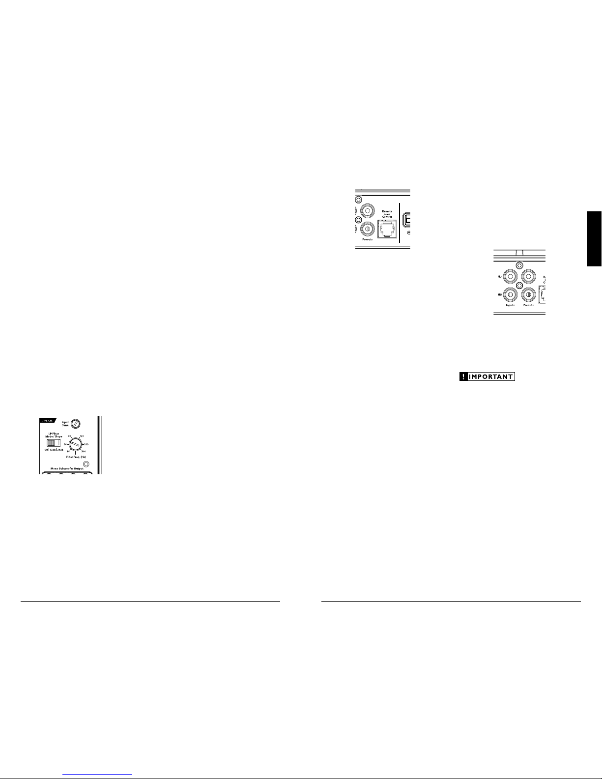
REMOTE LEVEL CONTROL OPTIONAL
With the add ition of the optional Remote
Level Cont rol (HD-RLC), you can control the
subwoofer volume from the front of the vehicle.
The HD-RLC connects to the jack labeled
“Remote Level Control” on the Connection Panel
of the amplifier usi ng a standard telephone cable
(supplied with the HD-RLC). If desired, mu ltiple
XD (and HD) ampl ifiers can be controlled from
a single H D-RLC controller u sing a simple phone
line “split ter” and multiple phone cables.
When connected to the a mplifier, the
HD-RLC operates as follows. At full counter-
clockwise rotation, the audio will mute
completely. At full clockw ise rotation the level
will be the same as if the HD-RLC was not
connected at all. In other words, it operates
strict ly as a level attenuator.
PREOUTS
The XD30 0/1 incorpor ates a pass-throug h
preamp output section, so t hat additional
amplif iers can be easily added to the system.
The preamp output delivers the same signal that
is connected to the X D300/1’s i nputs.
The preamp output signal by a ny crossover
filter selected (if the input signa l is full-range, t he
preamp output will be f ull-range).
If you plan to use t he “Preouts” to feed
a stereo amplifier, you must connect a
stereo signa l to the input of the amplifier.
A mono signal i nto the ampli fier will result
in a mono signa l out of the preamp output.
FILTER CONTROLS
Most speakers are not designed to reproduce
the full range of f requencies audible by the human
ear. For this reason, most speaker systems are
comprised of multiple speakers, each dedicated
to reproducing a specific frequency range. Filters
are used to select which frequency range is sent
to each section of a speaker system. The division
of frequency r anges to different speakers ca n be
done with passive filters (coils and /or capacitors
between t he amplifier outputs a nd the speakers),
which are acceptable and commonly used
for filtering between mid-range speakers and
tweeters. Filtering bet ween subwoofer systems
and satellite speaker systems is best done with
active filters, which cut off frequency content at
the input to the amplif ier. Active filters are more
stable tha n passive filters and do not introduce
extra neous resistance, which can degrade
subwoofer performance.
The active low-pass filter built into the X D300/1
is designed to attenuate frequencies above its
filter f requency, so that the system’s subwoofers
do not reproduce any aud ible midrange content.
This ser ves to improve tonal bala nce
and to avoid distortion. Correct use
of the filter can substantially improve
the fidelity of your aud io system.
2) LP Filter Ope ration: The low-pass filter in the
XD300/1 is fully va riable between 50 Hz a nd
500 Hz vi a the “Filter Freq.” control knob and
features t he ability to select b etween a moderate
“12dB” per oct ave or a steep “24dB” per oc tave
slope via t he “LP Filter Mode/Slope” switch.
Depending on the subwoofer system and
the vehicle, different slopes may be requ ired
to produce a smooth transit ion to the midbass spea kers in the system. E xperiment to
find the slope which be st matches the acoustic
requirements of your system.
Tuning Hint: A trunk mounted sub whose
output has to “ fight” throu gh a rear deck or a
back seat often benefit s from the 12 dB/octave
slope which let s more upper bass content pass
through. A sub that f ires directly i nto the
listeni ng environment is more likely to benefit
from a 24 dB/octave slope.
Note: The above hint is not “set-in-stone”…
You should always listen to the system caref ully to
determine the best choice as vehicle acoustics and
other factors play a big role in choosing the most
appropriate filter slope.
3) Precise Frequency Selection: T he filter
frequency markings on the front pa nel of
the ampli fier are for reference purposes and
are genera lly accurate to within 1/3 octave
or better. If you would like to select the f ilter
frequency w ith a higher level of precision,
consult Appendix B (pa ge 13) of this manual.
This cha rt gives you a more accurate frequency
for each of the forty detented positions of the
frequency selection control. This method can
be very useful if t he amplifier is mounted in
a location where you can’t see the f ront panel
markings easily.
4) Defeating the LP Filter: The Low-Pass filter
can also be defeated completely, by switching
the “LP Filter Mode/Slope” switch to the
“Off” position. This is usef ul if you are using
an exter nal active crossover i n the system.
With the internal crossover turned off, the
XD300/1’s upper frequenc y response limit is
500 Hz, due to its subwoofer-specific design.
10 | JL Audio - XD300/1 Owner’s Manual
11
ENGLISH
5) LED off / Ampl ifier Shuts Off Unexpectedly
The only condition that will shut down
an unda maged XD300/1 completely is if bat tery
voltage or remote tu rn-on voltage drops below
10 volts. The “Status LED” will turn of f when
this occurs. The amplif ier will turn back on
when voltage climbs back above 11 volts. If this
is happening in your system, have your charging
system and power wiri ng inspected.
For more informat ion on troubleshooting this
amplifier, refer to Appendix D (pages 14, 15).
SERVICING YOUR JL AUDIO AMPLIFIER
If your amplifier fa ils or malfunc tions, please
return it to your authorized JL Audio dealer so
that it may be sent in to JL Audio for ser vice.
There are no user serviceable parts or fuses inside
the ampli fier. The unique nature of t he circuitry
in the JL Audio amplif iers requires specifically
trained serv ice personnel. Do not at tempt
to service the amplifier you rself or through
unauthorized repair facilities. T his will not only
void the warranty, but may resu lt in the creation
of more problems within the a mplifier.
If you have any questions about the insta llation or
setup of the a mplifier not covered in t his manual,
please contac t your dealer or technical support.
JL Audio Technica l Support:
(954) 443-1100
9:00 AM – 5:30 PM (Eastern Time Zone)
Monday - Friday
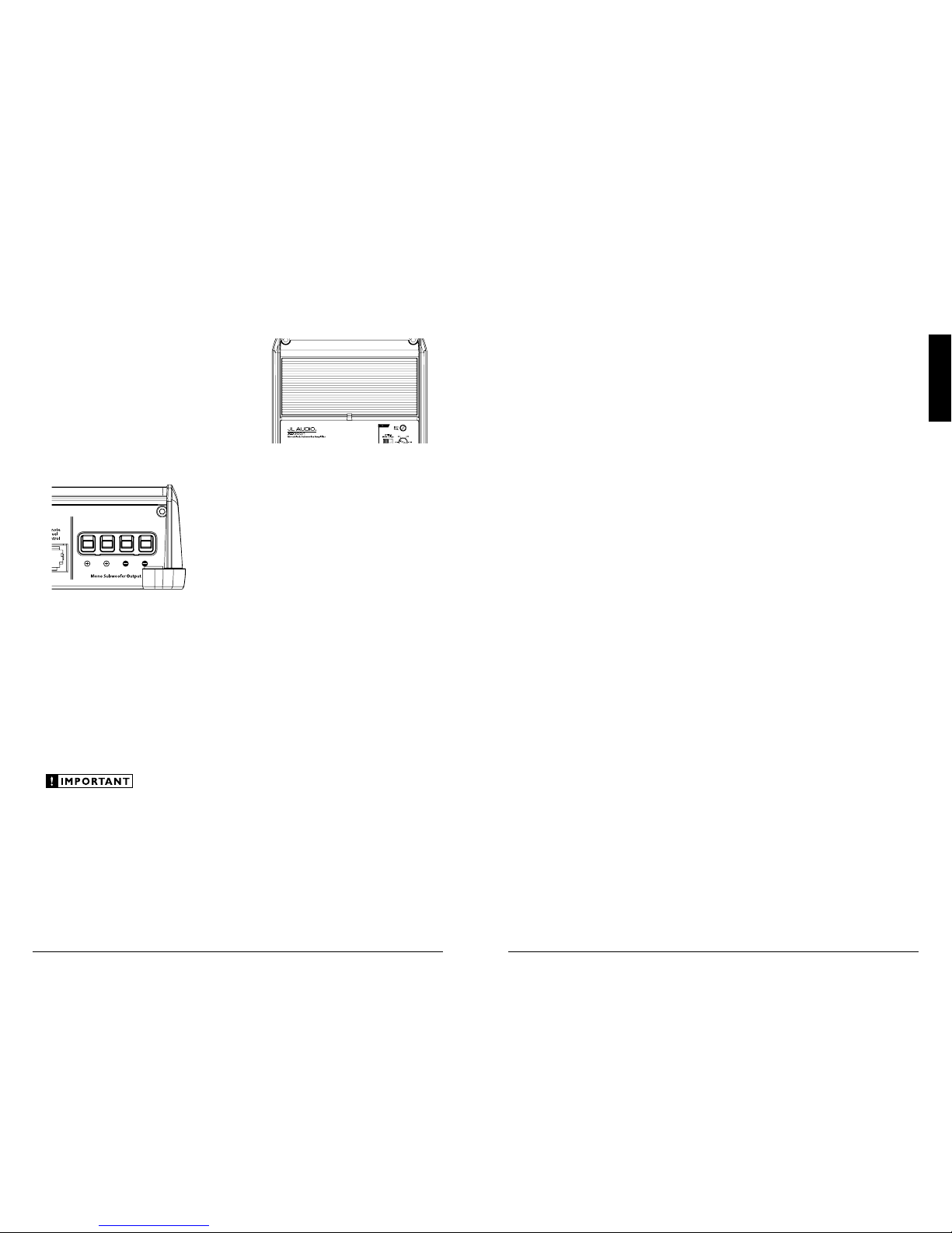
SUBWOOFER OUTPUTS
The XD30 0/1 is designed to deliver power into
subwoofer loads equ al to or greater than 2 oh ms.
The XD30 0/1’s subwoofer outputs are
designed to accept 16 AWG - 8 AWG wire. To
connect the subwoofer wires to the amplifier,
first back out the set screws on the top of t he
terminal block, using the supplied 2.5 mm hex
wrench. Strip 1/2 inch (12 mm) of insulation
from the end of each wire and insert the bare
wire into t he terminal block, seating it f irmly
so that no bare wire is ex posed. While holding
the wire in place, tighten the set screw firmly,
taki ng care not to strip the head of the screw.
You will notic e that there are t wo “+” positive
connections and two “–” negative con nections.
This is to facilitate multiple subwoofer wi ring.
The two positive and two negative connections
are connected in parallel inside the amplifier
They are not stereo outputs. Connecting two
subwoofers, each to one set of positive and
negative terminals, wil l result in a paral lel
subwoofer connection. If only connecting one
pair of subwoofer wires, it is not necessar y to use
both sets of connections.
Subwoofer loads below 2 ohms nominal are not
recommended a nd may cause the amplifier
to initiate a protection mode which reduces
power output.
STATUS LED / PROTECTION CIRCUITRY
There is a single multi-color LED on the top
surface of the ampli fier to indicate the a mplifier’s
operating status.
1) Fla shing Green: amplifier is powering up,
audio output is muted .
2) Constant Green: amplif ier is on and
functioning normally, audio output is active.
3) Constant Red: l ights to indicate that the
amplif ier has exceeded its safe operating
temperature, putting the amplifier into a
self-protection mode, which reduces the
peak power output of the amplifier. When its
temperature returns to a safe level, the red
light wi ll return to green and the amplifier will
return to f ull-power operating mode.
4) Constant Amber (yellow): Indicates
that an over-current condition has occurred and
is accompanied by a muting of t he amplifier’s
output. Because the muti ng behavior may be
very short i n duration, it may manifest itself as
an audible, repetitive ticking or thumping noise
in the output. Over-current conditions can be
caused by a speaker impedance lower t han the
optimum load impedance range for the amplif ier
or a short-circuit in the speaker wiring. The
latter can result from a short circuit between the
positive and negative speaker wires or between
either spea ker wire and the vehicle chassis.
The “Status LED” will remain amber for a few
seconds, even if the over-current condition is of a
very short duration.
 Loading...