

JL Audio XD1000/1V2 Owner's Manual
Thank you for purchasing a JL Audio amplifier for
your automotive sound system.
Your amplifier has been designed and manufactured to exacting
standards in order to ensure years of musical enjoyment in your vehicle.
For maximum performance, we highly recommend that you have
your new amplifier installed by an authorized JL Audio dealer. Your
authorized dealer has the training, expertise and installation equipment
to ensure optimum performance from this product. Should you
decide to install the amplifier yourself, please take the time
to read this manual thoroughly to familiarize yourself
with its installation requirements and setup procedures.
If you have any questions regarding the instructions in this
manual or any aspect of your amplifier’s operation, please contact your
authorized JL Audio dealer for assistance. If you need further assistance,
please call the JL Audio Technical Support Department
at (954) 443-1100 during business hours.
OWNER’S MANUAL
1000W Monoblock Class D Subwoofer Amplier

2 | JL Audio - XD1200/1v2 Owner’s Manual
3
ENGLISH
Cooling Efficiency Considerations:
The outer shell of your JL Audio amplifier is
designed to remove heat from the a mplifier
circuitry. For optimum cooling performance, this
outer shell shou ld be exposed to the largest
possible volume of a ir. Enclosing the ampli fier in
a small, poorly ventilated chamber can lead to
excessive heat build-up and degraded
performa nce. If an instal lation calls for an
enclosure around the amplifier, we recommend
that this enclosure be ventilated with the aid
of a fan. In normal applications, fan-cooling
is not necessary.
Mounting the amplifier upside down is
strongly discouraged.
If mounting the ampli fier under a seat,
make sure t here is at least 1 inch (2.5 cm) of
space above the amplif ier’s outer shell to permit
proper cooling.
Safety Considerations:
Your amplifier needs to be installed in a dr y,
well-ventilated environment and in a manner
which does not i nterfere wit h your vehicle’s safety
equipment (air bags , seat belt systems, ABS brake
systems, etc.). You should also take the time to
securely mount the amplifier so that it does not
come loose in t he event of a collision or a sudden
jolt to the vehicle.
Stupid Mistakes to Avoid
• Check before dril ling any holes in your vehicle
to make sure that you will not be drilling
through a gas tank, brake line, wiring harness or
other vital vehicle system.
• Do not run system wiring outside or underneath
the vehicle. This is an extremely dangerous
practice which can result in se vere damage to
your vehicle and person.
• Protect all system wires from sharp metal
edges and wear by caref ully routing them,
tying them down and using grommets and
loom where appropriate.
• Do not mount t he amplifier in t he engine
compart ment, under the vehicle, on the roof
or in any other area that w ill expose the
amplif ier circuitry to the elements.
PROTEC T YOUR HE ARING!
We value you as a long-term customer. For
that reason, we urge you to practice restraint in
the operation of this product so as not to da mage
your hearing and that of others in your vehicle.
Studies have shown that continuous exposure to
high sound pressure levels can lead to permanent
(irreparable) hearing loss. This a nd all other
high-power amplifiers are capable of producing
such high sound pressure levels when connected
to a speaker system. Please li mit your continuous
exposure to high volume levels.
While d riving, operate your audio system in
a manner that stil l allows you to hear necessary
noises to operate your vehicle safely (horns,
sirens, etc.).
SERIAL NUMBER
In the event that your amplifier requires
service or is ever stolen, you will need to have
a record of the product’s seria l number. Please
take the time to enter t hat number in the space
provided below. The serial number can be fou nd
on the bottom panel of the amplifier and on the
amplifier packaging.
Serial Number:
INSTALLATION APPLICATIONS
This ampl ifier is designed for operation in
vehicles with 12 volt, negative-ground electrical
systems. Use of this produc t in vehicles with
positive ground and/or voltages other than 12V
may result in d amage to the product and w ill void
th e war rant y.
This product is not certified or approved for
use in aircraft.
Do not attempt to “bridge” the outputs of this
amplif ier with the outputs of a second amplifier,
including an identica l one.
PLANNING YOUR INSTALLATION
It is important that you ta ke the time to read
this manual and t hat you plan out your
installation carefully. The following are some
considerations that you must take into account
when planning your installation.
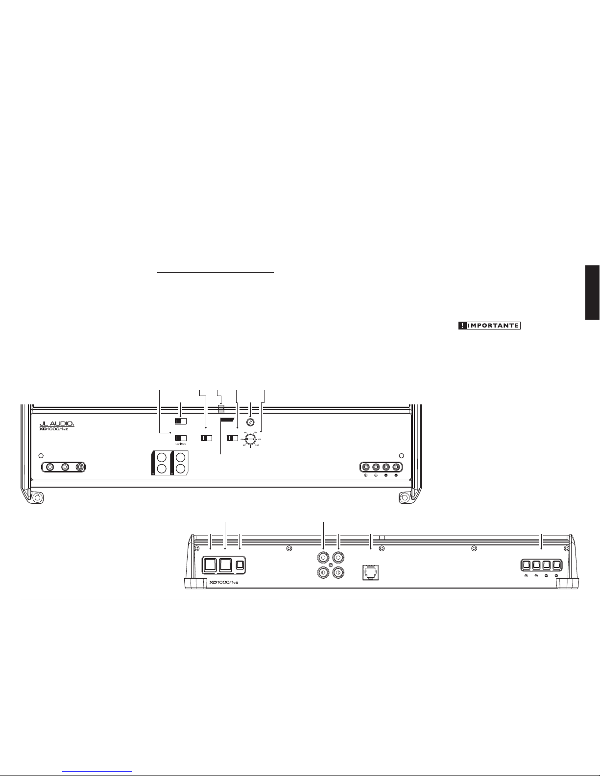
Status
LED
(pg. 11)
Filter
Frequency
Selector
(pg. 9)
LP Filter
Mode/Slope
Selection
(pg. 8)
Input Sensitivity
Control
(pg. 8)
Infrasonic
Filter
Selection
(pg. 9)
Input
Voltage
(pg. 7)
Turn-On
Mode
(pg. 6)
Remote Turn-On
Connector
(pg. 7)
Chassis Ground
Connector
(pg. 5)
Left & Right
Preamp Input Jacks
(pg. 7)
+12 V Power
Connector
(pg. 5)
Mono
Subwoofer Outputs
(pg. 10)
Jack for
Remote Level
Control Knob
(pg. 9)
Left & Right
Preamp Output Jacks
(pg. 10)

4 | JL Audio - XD1200/1v2 Owner’s Manual
5
ENGLISH
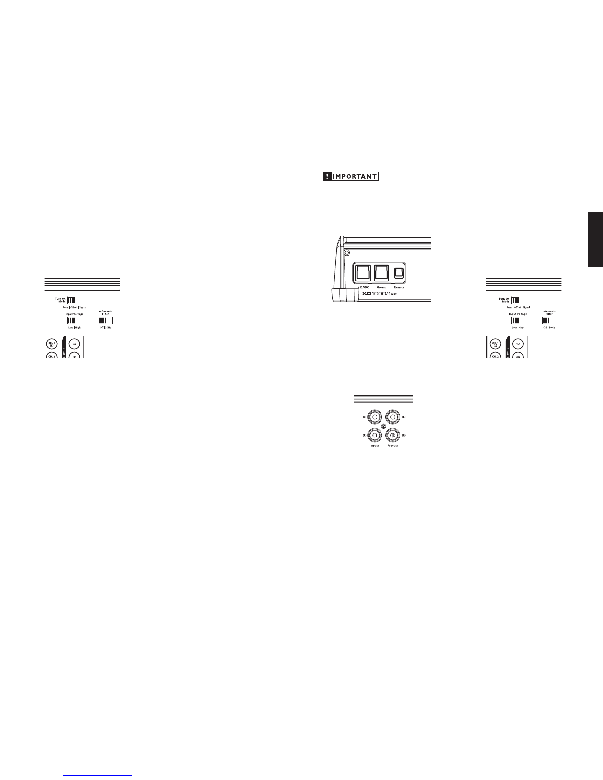
POWER CONNECTIONS
Before installi ng the amplifier, disconnect t he
negative (ground) wire f rom the vehicle’s battery.
This will prevent accidental d amage to the system,
the vehicle a nd your body during installation.
The XD1000/1v2’s “+12 V DC” and
“Ground” connections a re designed to
accept 4 AWG power wire. 4 AWG is the
required wire size for this amplifier.
If you are instal ling the XD1000/1v2 with
other amplifiers a nd wish to use a single ma in
power wire, use 2 AWG or 1/0 AWG main power
wire (dependi ng on the overall current demands
of all the amplif iers in the system). This 2 AWG
or 1/0 AWG power wire should terminate into
a fused distribution block mounted as close
to the amplifiers as possible (within 12 inches
/ 30cm of w ire length). The fused output of
the dist ribution block will connect to t he
XD1000/1v2 with 4 AWG power wire. JL Audio
ECS fused distribution block s are recommended
(XD-FDBU-2 and XD-FDBU-4)
Note: Smaller AWG numbers mean bigger wire
and vice-versa (1/0 AWG is the la rgest, 2 AWG is
smaller, then 4 AWG, then 8 AWG, etc.).
To connect the power wires to the amplifier,
first back out the set screw on the top of the
termina l block, using the supplied 2.5 mm hex
wrench. Strip 1/2 inch (12 mm) of insulation from
the end of each w ire and insert the bare wire i nto
the terminal block, seating it firm ly so that no
bare wire is exposed. Whi le holding the wire in
place, tig hten the set screw firmly, tak ing care not
to strip the head of the screw.
The ground connection should be made
using 4 AWG wire and should be kept as
short as possible, while accessing a solid
piece of sheet metal in the vehicle. The
surface of the sheet metal should be sanded
at the contact point to create a clean, meta lto-metal connection between the chassis
and the termination of the ground w ire.
For optimal groundi ng, we recommend the
use of a JL Audio ECS master ground lug
(XB-MGLU). Alternatively, a sheet metal
screw or bolt can be used with a star washer.
Any wires run through metal barr iers (such
as firewalls), must be protected with a high
qualit y rubber grommet to prevent damage to the
insulat ion of the wire. Failure to do so may result
in a dangerou s short circuit.
Many vehicles employ small (10 AWG -
6 AWG) wire to grou nd the battery to the
vehicle chassis and to connect the alternator’s
positive connection to the battery. To prevent
voltage drops, t hese wires should be upg raded
to 4 AWG when installing amplifier systems
with mai n fuse ratings above 60A.
FUSE REQUIREMENTS
It is absolutely vital that the main power
wire(s) to the amplifier(s) in the system be
fused w ithin 18 inches (45 cm) of the positive
battery post connection. The f use value at each
power wire shou ld be high enough for all of the
equipment being run from t hat power wire. If
only the X D1000/1v2 is being r un from that
power wire, use a 80A f use.
If fusing the amplifier nea r its power
connections (when more than one a mp is being
run from the mai n power wire), use an 80A fuse
(MAXI™ big plastic-body fuse is recommended).
PRODUCT DESCRIPTION
The XD1000/1v2 is a monoblock
amplif ier utilizing JL Audio Nex D™ high
speed switching technology to deliver
outstanding fidelity and efficiency.
The XD1000/1v2 can be operated with a w ide
variet y of source units and system configurations.
Its frequency response is l imited to the range
below 500 Hz. It is not designed for dr iving
midrange speakers or tweeters. Every aspect of its
operation has been optimized for low-frequency
amplif ication. For detailed specif ications, please
refer to Appendi x C (page 13).
TYPICAL INSTALLATION SEQUENCE
The followi ng represents the sequence
for a typical ampli fier installation, using an
aftermarket sou rce unit or OEM Interface
processor (like the CleanSweep CL441dsp).
Additional steps and different procedures may
be required in some applications. If you have
any questions, please contact your authorized
JL Audio dealer for assista nce.
1) Disconnect the negative battery post
connection and secu re the disconnected cable
to prevent accidental reconnection during
installation. This step is not optional.
2) Run 4 AWG power wire from the battery
location to the amplif ier mounting location,
taki ng care to route it in such a way that it will
not be damaged and will not interfere with
vehicle operat ion. Use 2 AWG or larger power
wire and a f used power distribut ion block if
additiona l amplifiers are being installed w ith
the XD1000/1v2.
3) Connec t power wire to the positive battery
post. Fuse the wire w ith an appropriate fuse
block (and connectors) within 18 inches (45
cm) wire length of the positive battery post.
This fus e is essential to protect t he vehicle.
Do not insta ll the fuse until t he power wire
has been sec urely connected to the a mplifier.
4) Run signal cables and remote turn-on w ire
from the source unit to t he final amplifier
mounting location.
5) Run speaker cables from the spea ker systems
to the amplifier mounting location.
6) Find a good, solid metal grou nding point
close to the a mplifier and connec t the
negative power wire to it using appropriate
hardware (use of t he JL Audio ECS master
ground lug, XB-MGLU is recommended).
Use 4 AWG wire, no longer than 36 i nches
(90 cm) from the a mplifier to the ground
connection point. In some vehicles, it may be
necessary to upgrade the battery grou nd wire.
(See page 5 for important notice).
7) Securely mount the amplif ier.
8) Con nect the positive and negative power
wires to t he amplifier. A fuse near the
amplif ier is not necessar y if the XD1000/1v2
is the only device bei ng run from the fused
main power wire. If the fused main power
wire is shared by the XD1000/1v2 and other
amplif iers or devices, fuse each amplifier/
device w ithin 12 inches (30 cm) of wire
length, v ia a fused distribution block
or multiple individual fuse blocks/
on-board f uses.
9) Connec t the remote turn-on wi re
to the ampl ifier or config ure the “Turn-On
Mode” switch for automatic turn-on.
10) Connec t the input cables to the amplifier.
11) Con nect the speaker cables to the amplifier.
12) Caref ully review the amplif ier’s control
settings to make su re that they are set
according to the needs of t he system.
13) Install the power wire fuse (80A for a
single X D1000/1v2) and reconnec t the
negative battery post termina l. Install the fuse
(80A) near the amplifier (if applicable).
14) Turn on the sou rce unit at a low level
to double-check that the a mplifier is
config ured correctly. Resist t he temptation
to crank it up until you have verified the
control settings.
15) Make necessary adjustments to the input
sensitivity controls to obtain t he right
overall out put and the desired balance
in the system. See Appendix A (page 12)
for the recommended input sensit ivity
setting method.
16) Enjoy the fruits of your labor with your
favorite music.
6 | JL Audio - XD1200/1v2 Owner’s Manual
7
ENGLISH
In signal and DC sensing applications, the
am plif ier’s “Remote” turn-on term inal becomes
a remote turn-on output. This allows the
XD1000/1v2 to turn on other amplifiers in the
audio system that do not have signal sensi ng.
INPUT SECTION
The XD1000/1v2 employs a d ifferential-
balanced input topolog y that provides the user
with a high degree of i nput flexibilit y, while
retaining superior noise reject ion. This type of
circuit also allows the XD1000/1v2 to accept high-
voltage inputs f rom factory source unit outputs
without excessive distortion or noise problems.
You may run a stereo or a mono signal into
the inputs of t he amplifier. The amplifier’s input
section automatical ly sums stereo signals to mono
for the internal ampli fier section. The a mplifier
will operate wit h only one input connection
but will require an increase i n input sensitivity
to overcome the loss of signal. If a mono input
signal is to be run, we recommend that you use
a “Y-adaptor” to split t he mono signal into both
inputs of the a mplifier. If you are feedi ng only
one input and using either the DC- Offset or
Signal S ensing “Turn-On Mode,” you must u se
the left-channel input for t he automatic turn-on
to operate.
Input Voltage Range:
Input Voltage Range: A wide range of sig nal
input voltages can be accom modated by the
XD1000/1v2’s input section (200mV – 8V).
This wide range is spl it up into two sub-ranges,
accessible via the “Input Voltage” switch :
“Low”: for preamp level signals
“High”: for speaker level signals
The “Low ” position on the “Input Voltage”
switch selects an input sensitiv ity range between
200mV and 2V. This means that the “Input Sens.”
rotary control will operate w ithin that voltage
window. If you are using an afterma rket source
unit, with conventiona l preamp level outputs, this
is the position you should select.
The “High” position on t he “Input Voltage”
switch selects an input sensitiv ity range between
800mV and 8V. This is useful for certain high-
output preamp level signals as well as speaker
level output from source units and small
amplif iers. To use speaker level sources, splice t he
speaker out put wires of the source unit or smal l
amplif ier onto a pair of RCA cables or plugs,
or use the JL Aud io ECS Speaker Wire to RCA
adaptor (XD-CLRAIC2-SW).
Line Output C onverters are usual ly not needed
with t he XD1000/1v2. If you find t hat the output
cannot be reduced sufficiently with a direct
speaker level signal applied to the amplif ier and
the “Input Voltage” switch in its “High” position,
you may use a Line Output Converter or voltage
divider to reduce the signal level.
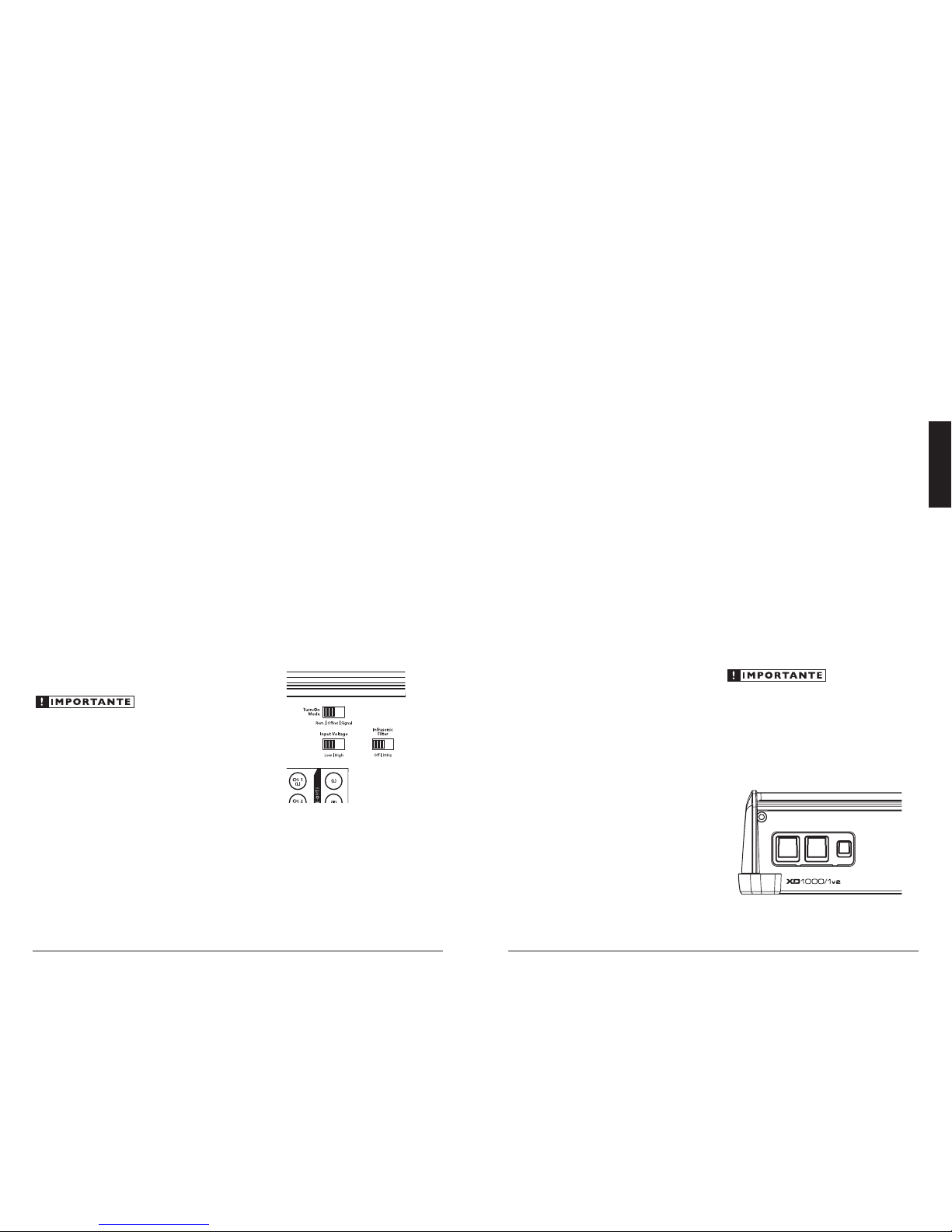
TURNON OPTIONS
The XD1000/1v2 can be switched on and of f
using one of th ree methods, determ ined by the
position of t he amplifier’s “Turn-On Mode”
switch. Ple ase read these option s and decide
which is best suited for your specif ic system.
1) +12V remote turn-on lead (preferred)
2) Signal-sensing turn-on circuit
3) DC offset-sensing tur n-on circuit
+12 V Remote Turn-On : This is the preferred
method for tu rning the amplifier on/off. T he
amplif ier will turn on when +12 V is present at
its “Remote” input and turn off when +12 V is
switched of f. This +12 V remote turn-on signa l is
typically controlled by a source unit's remote
turn-on wire. The XD1000/1v2’s “Remote” turnon connector will accept 18 AWG – 12 AWG
wire. To connect t he remote turn-on wire to
the ampli fier, first back out the set screw on the
top of the terminal block, using t he supplied 2.5
mm hex wrench. Strip 1/2 inch (12mm) of wire
and inser t the bare wire into the terminal block,
seating it f irmly so that no bare wire is ex posed.
While holding the w ire in the terminal, tighten
the set screw firmly, taki ng care not to strip the
head of the screw and mak ing sure that the wire
is firmly gripped by the set screw.
If a source un it does not have a dedicated
remote turn-on output, consider one of t he
following a lternative turn-on options:
These methods are useful when a conventional
+12 V remote turn-on signal is not available in a
system. These allow you to operate the amplif ier
without hav ing to locate a remote turn-on lead at
the source u nit, which can be ver y useful when
interfacing the amplifier with OEM (factory)
audio systems that do not use conventional +12 V
turn-on leads.
Depending on the cha racteristics of the audio
signal, one of the following methods may work
better t han the other. We recommend trying DC
Offset-Sensing first as it does not require a long
delay to turn the system off af ter the signal is
shut off.
DC Offset-Sensing: The a mplifier will turn on
and off by detecting the presence of a very smal l
DC signa l (of fset) that is typical in the audio
output of most OEM (factory) source units and
amplif iers. The amplifier will turn on and off in
reaction to the presence or absence of t his DC
Offset. The sensitivity of t his circuit is desig ned
for high-level (spea ker level) signals, not for lowlevel (preamp level) signals. The circuit senses t he
left-channel signa l only.
Signal-Sensi ng: The amplifier w ill turn on and
off by detecting the presence of a fu ll-range
audio signa l at its left-channel input. After
approximately 30 seconds, the amplifier will shut
off. The sensitivit y of this circuit is designed for
high-level (spea ker level) signals, not for low-level
(preamp level) signals. The circuit is tuned to
react to signals at mid-range frequencies. This
prevents false switching from sig nals created by
moving loudspeakers that are in paral lel with the
amplif ier’s input signal.
8 | JL Audio - XD1200/1v2 Owner’s Manual
9
ENGLISH
Note: The above hint is not “set-in-stone”…
You should always listen to the system caref ully to
determine the best choice as vehicle acoustics and
other factors play a big role in choosing the most
appropriate filter slope.
3) Precise Frequency Selection: The filter
frequency markings on the front pa nel of
the ampli fier are for reference purposes and
are generally accurate to within 1/3 octave
or better. If you would like to select the f ilter
frequency w ith a higher level of precision,
consult Appendix B (page 13) of this manua l.
This cha rt gives you a more accurate frequency
for each of the forty detented positions of the
frequency selection control. This method can
be very useful if the amplifier is mounted in
a location where you can’t see the f ront panel
markings easily.
4) Defeating the LP Filter: The Low-Pass filter
can also be defeated completely, by switching
the “LP Filter Mode/Slope” switch to the
“Off” position. This is usef ul if you are using
an external act ive crossover in the system.
With the internal crossover turned off, the
XD1000/1v2’s upper frequency response l imit is
500 Hz, due to its subwoofer-specific design.
INFRASONIC FILTER
The “Infrasonic Fi lter” is a 24 dB/octave high-
pass filter, with a fixed cutoff frequency of 30 Hz.
This filter is designed to conserve amplifier power
and protect subwoofer systems, without aud ibly
degrading the sub-bass output.
With ported enclosures, the use of t he
“Infras onic Filter” is high ly recommended to
protect the speaker(s) from excessive excursion
below box tuning.
With sealed enclosures, the use of the filter
is less necessary, but can stil l help protect the
speaker system from excessive excursion.
The “Infrasonic Fi lter” can be completely
defeated by selecting the “Off ” position on its
switch. This bypasses all signa l from flowing
through the circuit.
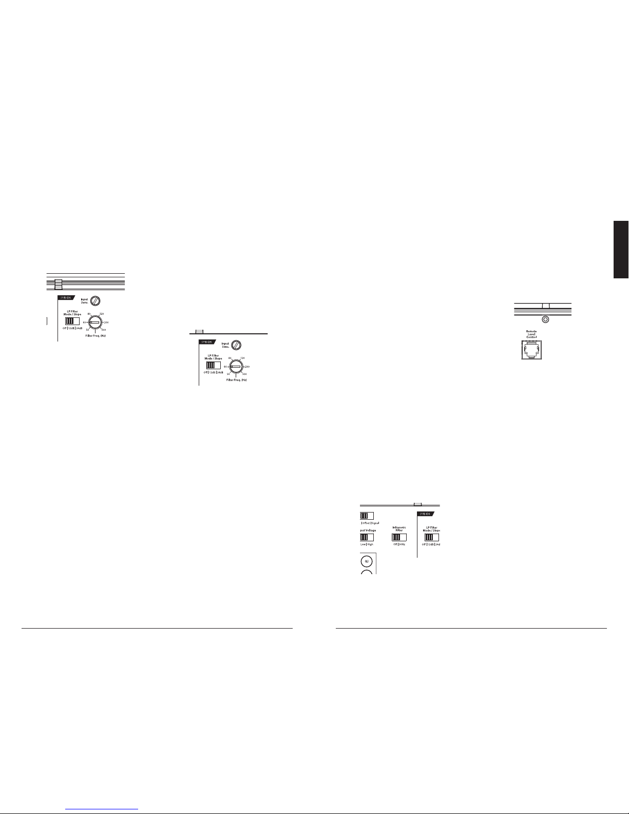
REMOTE LEVEL CONTROL OPTIONAL
With the add ition of the optional Remote
Level Cont rol (HD-RLC), you can control the
subwoofer volume from the front of the vehicle
The HD-RLC connects to the jack labeled
“Remote Level Cont rol” on the Connection
Panel of the amplifier usi ng a standard telephone
cable (supplied with the HD-RLC). If desired,
multiple X D (a nd HD) amplifiers can be
controlled from a single HD-R LC controller
using a single-line, four-wire phone li ne splitter
and multiple phone cables.
When connected to the a mplifier, the
HD-RLC operates as follows: At f ull counter-
clockwise rotation, the audio will mute
completely. At full clockw ise rotation the level
will be the same as if the HD-RLC was not
connected at all. In other words, it operates
strict ly as a level attenuator.
INPUT SENSITIVITY CONTROLS
The control labeled “Input Sens.” can be u sed
to match the sou rce unit’s output voltage to the
input stage of the X D1000/1v2 for ma ximum
clean output. Rotating the control clockwise wil l
result in higher sensitivity (louder for a given
input voltage). Rotating the control counterclockwise will result i n lower sensitivity (quieter
for a given input voltage).
To properly set the ampli fier for maximum
clean output , please refer to Appendix A (page
12
) in this manual. After using this procedure,
you can then adjust the “Input Sens.” levels
downward if t his is required to achieve the
desired system balance.
Do not increas e any “Input Sens.” setting for
any channel(s) of any amplifier i n the system
beyond the ma ximum level establis hed during
the procedu re outlined in Appendix A (page 12).
Doing so wi ll result in audible distortion and
possible spea ker damage.
FILTER CONTROLS
Most speakers are not designed to reproduce
the full range of f requencies audible by the human
ear. For this reason, most speaker systems are
comprised of multiple spea kers, each dedicated
to reproducing a specific frequency range. Filters
are used to select which frequency range is sent
to each section of a speaker system. The division
of frequency ranges to different speakers ca n be
done with passive filters (coils and /or capacitors
between t he amplifier outputs a nd the speakers),
which are acceptable and commonly used
for filtering between mid-range speakers and
tweeters. Filtering between subwoofer systems
and satellite speaker systems is best done with
active filters, which cut off frequency content at
the input to the amplif ier. Active filters are more
stable than passive f ilters and do not introduce
extra neous resistance, which can degrade
subwoofer performance.
The active low-pass filter built into the
XD1000/1v2 is designed to at tenuate frequencies
above its fi lter frequency, so that the system’s
subwoofers do not reproduce any audible
midra nge content.
This ser ves to improve tonal balance
and to avoid distortion. Correct use
of the fi lter can substantially improve
the fidelity of your aud io system.
2) LP Filter Ope ration: The low-pass filter in the
XD1000/1v2 is ful ly variable between 50 Hz
and 500 Hz v ia the “Filter Freq.” control k nob
(80 Hz is a good starting point for tuning most
systems). The filter also features the ability to
select bet ween a moderate “12dB” per oc tave
or a steep “24dB” per oc tave slope via the “LP
Filter Mode/Slope” switch.
Depending on the subwoofer system and
the vehicle, different slopes may be requ ired
to produce a smooth transit ion to the midbass spea kers in the system. E xperiment to
find the slope which best matches t he acoustic
requirements of your system .
Tuning Hint: A trunk mounted sub whose
output has to “ fight” throu gh a rear deck or a
backseat of ten benefits from the 12 dB/octave
slope which lets more upper bass content pass
through. A sub that f ires directly into the
listeni ng environment is more likely to benefit
from a 24 dB/octave slope.
10 | JL Audio - XD1200/1v2 Owner’s Manual
11
ENGLISH
STATUS LED / PROTECTION CIRCUITRY
There is a single multi-color LED on the top
surface of the ampli fier to indicate the a mplifier’s
operating status.
1) Flashing Green: amplifier is powering up,
audio output is muted.
2) Constant Green: amplif ier is on and
functioning normally, audio output is active.
3) Constant Red: lights to indicate that the
amplif ier has exceeded its safe operating
temperature, putting the amplifier into a
self-protection mode, which reduces the
peak power output of the amplifier without
muting the aud io. When its temperature returns
to a safe level, t he red light will ret urn to green
and the amplifier will return to f ull power
operating mode.
4) Constant Amber (Yellow): Indicates
that an over-current condition has occurred and
is accompanied by a muting of t he amplifier’s
output. Because the muting behavior may be
very short in duration, it may manifest itself as
an audible, repetitive ticking or thumping noise
in the output. Over-current conditions can be
caused by a speaker impedance lower t han the
optimum load impedance range for the amplif ier
or a short-circuit in the speaker wiring. The
latter can result from a short circuit between the
positive and negative speaker wires or between
either spea ker wire and the vehicle chassis.
The “Status LED” w ill remain amber for a few
seconds, even if the over-current condition is of a
very short duration.
5) LED off / Amplifier Shuts Off Unexpectedly
The only condition that will shut down
an unda maged XD1000/1v2 completely is i f
battery voltage or remote turn-on voltage drops
below 10 volts. The “Status LED” wil l turn off.
when this occurs. The amplifier wi ll turn back
on when voltage climbs back above 11 volts.
If this is happening in your system, have your
charging system and power wiring inspected.
For more information on troubleshooting this
amplifier, refer to Appendix D (pages 14, 15).
SERVICING YOUR JL AUDIO AMPLIFIER
If your amplifier fa ils or malfunc tions, please
return it to your authorized JL Audio dealer so
that it may be sent in to JL Audio for ser vice.
There are no user serviceable par ts or fuses inside
the ampli fier. The unique nature of t he circuitry
in the JL Audio amplif iers requires specifically
trained serv ice personnel. Do not attempt
to service the amplifier you rself or through
unauthorized repair facilities. T his will not only
void the warranty, but may resu lt in the creation
of more problems within the a mplifier.
If you have any questions about the insta llation or
setup of the a mplifier that have not been covered
in this manual, please contact your dealer or
technica l support.
JL Audio Technica l Support:
(954) 443-1100
9:00 AM – 5:30 PM (Eastern Time Zone)
Monday - Friday
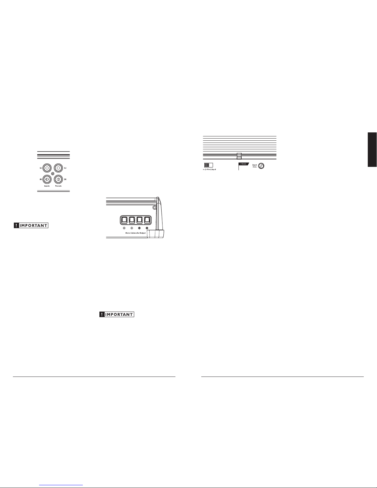
PREOUTS
The XD1000/1v2 incor porates a buffered, pass-
through preamp output section, so t hat additional
amplif iers can be easily added to the system.
The preamp output delivers the same signal that
is connected to the X D1000/1v2’s inputs.
The preamp output signal is not affected by
the amplifier’s LP Filter (if the input signal is ful l-
range, the preamp output w ill be full-ra nge).
If you plan to use t he “Preouts” to feed
a stereo amplifier, you must connect a
stereo signa l to the input of the amplifier.
A mono signal i nto the ampli fier will result
in a mono signa l out of the preamp output.
SUBWOOFER OUTPUTS
The XD1000/1v2 is designed to deliver power
into subwoofer loads equal to or greater tha n 2
ohms of nominal impedance.
The XD1000/1v2’s subwoofer output s are
designed to accept 16 AWG - 8 AWG wire. To
connect the subwoofer wires to the amplifier,
first back out the set screws on the top of t he
termina l block, using the supplied 2.5 mm hex
wrench. Strip 1/2 inch (12 mm) of insulation
from the end of each wire and insert the bare
wire into t he terminal block, seating it f irmly
so that no bare wire is ex posed. While holding
the wire i n place, tighten the set screw fi rmly,
taki ng care not to strip the head of the screw.
You will notic e that there are t wo “+” positive
connections and t wo “–” negative connections.
This is to facilitate multiple subwoofer wiring.
The two positive and two negative connections
are connected in parallel inside the amplifier.
They are not stereo outputs. Connecting two
subwoofers, each to one set of positive and
negative terminals, wil l result in a parallel
subwoofer connection. When only connecting
one pair of subwoofer wires, it is not necessar y to
use both sets of connections.
Subwoofer loads below 2 ohms nominal are not
recommended a nd may cause the amplifier
to initiate a protection mode, which reduces
power output.

12 | JL Audio - XD1200/1v2 Owner’s Manual
13
ENGLISH
APPENDIX B:
Precise Frequency Selection Chart
“FILTER FREQ” AMP FILTER
Detent Panel Actual
Number Marking Freq.
Full counter-clockwise: 53
01 ............................53
02 ...........“50” ............53
03 ............................54
04 ............................54
05 ............................55
06 ............................57
07 ............................59
08 ...........“60” ............61
09 ............................63
10 ............................65
11 ............................67
12 ............................70
13 ............................72
14 ............................75
15 ............................78
16 ...........“80” ............81
17 ............................85
18 ............................88
19 ............................93
20 .......“12 o’clock” ........97
21 ...........................102
22 ...........................107
23 ...........................113
24 ..........“120” ..........120
25 ...........................127
26 ...........................135
27 ...........................144
28 ...........................156
29 ...........................169
30 ...........................184
31 ...........................203
32 ..........“200” ..........227
33 ...........................254
34 ...........................290
35 ...........................337
36 ...........................392
37 ...........................426
38 ..........“500” ..........447
39 ...........................467
Full-clockwise: 470
APPENDIX C:
XD1000/1v2 Specifications
General Specifications:
Recommended Fus e Value: 80A
Recommended Fus e Type: MAXI® or AGU
Input Sections:
No. of Inputs: O ne Stereo Pair
Input Type: Dif ferential-balanced with RC A jack inputs
Input Range: 20 0mV - 8V RMS
Amplifier Section:
Amplifier Topology: NexD™ High Speed Class D
Power Supply: Unregulated MOSFET switching type
Rated Power a t 14.4V with less than
1% THD+Noise (20 Hz - 20 kHz)
600W RMS x 1 @ 4 ohms
800W RMS x 1 @ 3 ohms
1000W RMS x 1 @ 2 ohms
Rated Power @ 12.5V with less than
1% THD + Noise (20Hz - 20 kHz)
500W RMS x 1 @ 4 ohms
650W RMS x 1 @ 3 ohms
800W RMS x 1 @ 2 ohms
Signal to Noise R atio:
>83 dB referred to rated p ower
(A-weighted, 20 Hz-20 kHz nois e bandwidth)
>53 dB referred to 1W
(A-weighted, 20 Hz-20 kHz nois e bandwidth)
Frequency Response: 7 Hz - 500 Hz (+0, -1dB)
Damping Factor:
>1000 @ 4 ohms / 50 Hz
>500 @ 2 ohms / 50 Hz
Amplifier Filters:
Amplifier Low-Pass Filter:
State-variabl e, 12 dB /octave But terworth or 24 dB/octave
Linkwitz-Riley with continuously variable cutoff frequency
selectio n from 50 - 500 Hz (defeatable).
Infrasonic Filter:
24 dB/octave Butter worth @ 30 Hz (defeatable).
Preamp Output:
Buffered p ass-through type.
Dimensions(LxWxH):
14.73” x 7.09” x 2.05” (374m m x 180mm x 52mm)
APPENDIX A:
Input Sensitivity Level Setting
Following the directions below w ill allow the
installer to adjust t he input sensitivity of each
amplif ier channel pair simply and easily in just a
few minutes using equipment which is common ly
available in installation bays.
Necessary Equipment
• Digital AC Voltmeter
• CD with a sine-wave test tone recorded at
0 dB reference le vel in the frequency range
to be amplified for that set of channels
(50 Hz for subwoofer channels, 1 kHz for a
midrange application). Do not use attenuated
test tones (-10 dB, -20 dB, etc.).
The Nine-Step Procedure
1) Disconnect t he speaker(s) from the
amplif ier’s speaker out put connectors.
2) Turn off all processing (bass/treble, loudness,
EQ, etc.) on the source unit, processors (if
used) and amplifier. Set fader control to center
position and subwoofer level control to 3/4 of
maxi mum (if used to feed the X D1000/1v2).
3) Turn the amplifier’s “Input Sens.” control all
the way down.
4) Set the source unit volume to 3/4 of full
volume. This will allow for reasonable gain
overlap with moderate clipping at full volume.
5) Using t he chart on this pa ge, determine the ta rget
voltage for input sen sitivity adjust ment according
to the nomin al impedance of t he speaker system
connecte d to the amplifier out puts.
6) Verify that you have disconnected the speakers
before proceed ing. Play a track with an
appropriate sine wave (within t he frequency
range to be amplif ied by the XD1000/1v2) at
3/4 source unit volume.
7) Connect the AC voltmeter to t he speaker output
connectors of t he amplifier. Make sure you test
the voltage at t he correct connectors (+ and –).
8) Increase the “Input Sens.” control until the
target voltage is obser ved with the voltmeter.
9) Once you have adjusted the X D100 0/1v2 to
its maximum low-distortion output level,
reconnect the speaker(s). The “Input Sens.”
controls can now be adjusted downward if the
amplif ier requires attenuation to achieve the
desired system balance.
Do not increase any “Input Sens.” setting for
any amplif ier channel or channe l pair in the
system beyond t he maximum level established
during this procedure. Doing so will resu lt in
audible distor tion and possible speaker damage.
It will be necessary to re-adjust the
“Input Sens.” if any equalizer boost is activated
after setti ng the “Input Sens.” with this
procedure. This applies to any EQ boost circuit,
including source unit tone controls or EQ
circuits. EQ cuts will not requ ire re-adjustment.
Nom. Impedance Target AC Voltage
4 63.2 V
3 49.0 V
2 34.6 V
1
Not Recommended
Due to ongoing product development, all specifications are subject to
change without notice.

14 | JL Audio - XD1200/1v2 Owner’s Manual
15
ENGLISH
“My amplif ier shuts off once in a wh ile, usually at higher vo lumes.”
Check your voltage source and grounding point. The power supply
of the XD1000/1v2 will oper ate with chargi ng system
voltages down to 10V. Shutdown problems at higher volume
levels can occur when the charg ing system voltage (or remote
turn-on voltage) drops below 10V. These dips c an be of very
short durat ion making them ex tremely difficult to detec t
with a common DC voltme ter. To ensure proper voltage,
inspect all wiring and termination points. It may also be
necessary to upgrade the ground wire connecting the battery
to the vehicle’s chassis and the power wire connecting the
alter nator to the batter y. Many vehicles employ smal l (10
AWG - 6 AWG) wire to grou nd the battery to the vehicle’s
chassis a nd to connect the alter nator to the battery. To prevent
voltage drops , these wires should be upgraded to 4 AWG
when installi ng amplifier systems with m ain fuse ratings
above 60A. Grounding problems are the leading cause of
misdia gnosed amplifier “failures.”
“My amplif ier turns on, but ther e is no output.”
Check the input signa l using an AC voltmeter to measure the
voltage from t he source unit while an appropriate test tone is
played through the source unit (disconnect the input cables
from the amplifier prior to this test). The frequency used
should be in t he range that is to be amplified by t he amplifier
(example: 50 Hz for a sub bass application or 1 kHz for a f ull
range / hig h-pass applic ation). A steady, suff icient voltage
(between 0.1 and 4.0 -volts) should be pres ent at the output of
the signa l cables.
Check the output of the amplifier. Using the procedure explained in
the previous check item (after plugging the input cables back
into the ampl ifier) test for output at the speaker outputs of
the ampli fier. Unless you enjoy test tones at hig h levels, it is
a good idea to remove the speaker wires from the amplifier
while doing this. Turn the volume up approxi mately
halfway. 5 volt AC or more should be measured at the
speaker out puts. This output level can vary greatly between
amplif iers but it should not be in the mi llivolt range with
the source u nit at half volume. If you are reading sufficient
voltage, check your spea ker connections as explained below.
Check to ensure that the spea ker wires are mak ing a good
connection with the metal inside the ter minal block. The
speaker w ire connectors are designed to accept up to 8 AWG
wire. Ma ke sure to strip the wi re to allow for a sufficient
connection with the metal inside the ter minal block.
“How do I prop erly set the input sens itivity on my amplif ier?”
Please refer to Appendix A (page 12) to set t he input sensitivity for
maximum, low-distortion output.
“My amplif ier doesn’t turn on.”
Check the fuse, not just visually, but wit h a continuity meter. It is
possible for a fu se to have poor internal connections t hat
cannot be fou nd by visual inspection. It is best to take t he
fuse out of the holder for testing. If no problem is fou nd with
the fuse, inspect the fu se holder.
Check the integrity of the con nections made to each of the
“+12V DC,” “Ground ,” and “Remote” terminals. Ensure
that no wire insulation is pinched by the terminal set screw
and that each connect ion is tight.
Check to make sure there is +12V at the “Remote” connection of the
amplif ier. In some cases, the t urn-on lead from the sou rce unit
is insuf ficient to turn on multiple devic es and the use of a relay
is required. To test for this problem, jump the “+12V DC ” wire
to the “Remote” termina l to see if the ampli fier turns on.
“I hear a repetitive ticking or popping sound coming out of the speaker(s).”
Check the speaker wires for a possible short, either bet ween the
positive and negative leads or between either spea ker lead
and the vehicle’s chassis ground. If a shor t is present, you will
experience distorted and/or attenuated output. T he “Status
LED” will tu rn amber in this sit uation. It may be helpful to
disconnect the speaker wi res from the amplif ier and use a
different set of wires connected to a test spea ker.
Check the nominal load impedance to verify that the ampli fier is
drivi ng a load equal to or greater t han 2 ohms.
“My amplif ier’s output fluc tuates when I tap on it or hi t a bump.”
Check the connect ions to the amplifier. Ma ke sure that the
insulat ion for all wires has been stripped back far enough to
allow for a good contact area inside the termina l block.
Check the input connectors to ensure that they all are making good
contact wit h the input jacks on the amplifier.
APPENDIX D: TROUBLESHOOTING

16 | JL Audio - XD1200/1v2 Owner’s Manual
17
ENGLISH
INSTALLATION NOTES:
Use this diagram to document your amplifier’s switch and control positions.
LIMITED WARRA NTY AMPLIFI ERS USA
JL AUDIO warrants this product to be free of defects in materials and workmanship for a
period of two (2) years. The war ranty is extended to t hree (3) years tota l if installation is performed by an
authoriz ed JL Audio dealer usi ng a JL Audio Premium Power Connection System for power w iring.
This warranty is not transferrable a nd applies only to the original purchaser from an authori zed
JL AUDIO dealer. Shou ld service be necessar y under this war ranty for any reason due to manufacturing
defect or ma lfunction, JL AUDIO will (at its d iscretion), repair or replace the defective produc t with new
or remanufactured product at no cha rge. Damage caused by the follow ing is not covered under warranty:
accident, misuse, abuse, product mod ification or neglect, failure to follow installation instructions,
unauthorized repair attempts, misrepresentations by t he seller. This warranty does not cover incidenta l
or consequential damages and does not cover the cost of removing or reinstalling t he unit(s). Cosmetic
damage due to accident or norma l wear and tear is not covered u nder warranty.
Warranty is voi d if the product’s seri al number has been re moved or defaced.
Any applicable implied warranties are limited in duration to the period of the express warranty as
provided herein beginning wit h the date of the original purchase at retail, and no wa rranties, whet her
express or implied, sha ll apply to this product t hereafter. Some states do not a llow limitations on implied
warra nties, therefore these exclusions may not apply to you. This warranty gives you specific legal rights,
and you may also have other rights which vary from state to state.
If you need se rvice on your JL AUDIO pro duct:
All wa rranty retur ns should be sent to JL AUDIO ’s Amplif ier Service Facility freight-prepaid throug h
an authorized JL AUDIO dealer and must be accompa nied by proof of purchase (a copy of the orig inal
sales rec eipt). Direct returns from consumers or non-author ized dealers will be refused u nless specifically
authoriz ed by JL AUDIO with a valid return authoriz ation number.
Warranty expiration on products returned without proof of purchase will be determined from the
manufacturing date code. C overage may be invalidated as this date is prev ious to purchase date. Nondefective items received w ill be returned f reight-collect. Customer is responsible for shipping charges and
insura nce in sending the product to JL AUDIO. Freight damage on returns is not covered under warranty.
For Service Information in the U.S.A. please call
JL Audio Customer Service: (954) 443-1100
9:00 AM – 5:30 PM (Eastern Time Zone)
JL Audio, Inc
10369 North Commerce Pkw y.
Miram ar, FL 33025
(do not send produc t for repair to this address)
International Warranties:
Products purc hased outside the United States of America are covered only
by that country’s distributor and not by JL Audi o, Inc.
Printed in China
XD1000/1v2 MAN-01-30-2013
Muchas gracias por adquirir un amplificador JL Audio para
el sistema de audio de su automóvil.
El amplificador se ha diseñado y fabricado de acuerdo con normas rigurosas
a fin de asegurarle que disfrutará de la música en su vehículo durante
muchos años. Para un rendimiento óptimo, recomendamos que su nuevo
amplificador sea instalado por un distribuidor autorizado de JLAudio.
Eldistribuidor autorizado cuenta con la capacitación, la pericia y los
equipos de instalación necesarios para asegurar el rendimiento óptimo de
este producto. En el caso de que decida instalar usted mismo el amplificador,
lea atentamente este manual para familiarizarse con los requisitos de la
instalación y los procedimientos de configuración.
Si tiene alguna duda relacionada con las instrucciones dadas en este
manual o con cualquier aspecto del funcionamiento del amplificador,
póngase en contacto con un distribuidor autorizado de JL Audio para
solicitar asistencia . Si necesita más ayuda, llame al Departamento de
Soporte Técnico de JL Audio al (954) 443-1100 en los EE. UU. durante horas
normales de oficina .
MANUAL DEL PROPIETARIO
Amplicador monobloque de subwoofer clase D de 1000 W
2 | JL Audio - XD1200/1v2 Manual del Propietario
3
ESPAÑOL
Consideraciones relativas a la eficiencia de
enfriamiento:
La carca sa externa de su amplificador JL Audio
se ha diseñado para eliminar el calor del circuito
del amplificador. Para logra r el rendimiento
de enfriamiento óptimo, la carcasa debe estar
expuesta al mayor volumen de a ire posible.
Si el amplif icador se coloca en una cá mara
pequeña con escasa venti lación, se producirá una
acumulación de calor excesiva y se degradará
el rendimiento. Si la insta lación requiere un
espacio envuelto alrededor del amplificador,
recomendamos que este se ventile con la ayuda de
un ventil ador. Para aplicaciones normales, no se
requiere enf riamiento con un ventilador.
Se desal ienta firmemente montar el
amplificador boca abajo.
Si se monta el amplificador debajo de
un asiento, asegúrese de que haya por lo
menos 2,5cm (1 pulgada) por encima de la
carcasa del amplificador pa ra permitir un
enfria miento adecuado.
Consideraciones relativas a la seguridad:
El amplificador se debe instalar en un
lugar seco y bien ventilado, y de manera que
no interfiera con los equipos de seguridad
del vehículo (bolsas de aire, sistemas de
cinturones de seguridad, sistemas de frenos
ABS, etc.). Debe dedicar tiempo a montar
el amplif icador de manera segu ra a fin de
que no se suelte si se produce un choque
o el vehículo da un salto repentino.
+12 VDC Ground Remote
Mono Subwoofer Output
Remote
Level
Control
Inputs Preouts
(R)(R)
(L)(L)
Conector de
alimentación
de +12 V
(pág. 5)
Conector de
toma a tierra del
chasis
(pág. 6)
Conector de
encendido
remoto
(pág. 7)
Conectores de
entrada de bajo
nivel izquierdo y
derecho (pág. 8)
Conectores de
salida de bajo nivel
izquierdo y
derecho (pág. 10)
Conector para la
perilla de control
de nivel remoto
(pág. 10)
Salidas mono de
subwoofer
(pág. 11)
PROTEJA SU AUDICIÓN!
Lo valoramos como cliente a largo plazo.
Por ello, lo instamos a utilizar este producto
con cautela para no dañar su audición y la de
sus acompañantes en el vehíc ulo. Los estudios
realizados han demostrado que una exposición
continua a niveles de presión de sonido muy
altos puede provocar pérdida de audición
permanente (irreparable). Tanto este como otros
amplif icadores de alta potencia pueden producir
niveles de presión de sonido muy elevados
cuando se conectan a u n sistema de altavoces. Le
recomendamos que limite la exposición continua
a niveles de volumen altos.
Mientras conduce, use su sistema de audio
de manera que le permita escuchar los r uidos
necesarios para conducir de manera segura
(bocinas, sirenas, etc.).
NÚMERO DE SERIE
En el caso de que necesite repa rar su
amplif icador o si se lo roban, deberá tener
registrado el número de serie del producto.
No deje de anota r dicho número en el espacio
provisto a continuación. El número de serie se
encuentra en el panel inferior del amplificador y
en el embalaje del producto.
Número de serie:
+12 VDC Ground Remote
Turn-On Mode
Rem. | Oset | Signal
Low | High
Infrasonic
Filter
O | 30Hz
Input Voltage
LP Filter
Mode/Slope
Filter Freq. (Hz)
O | 12dB | 24dB
Input
Sens.
Mono Subwoofer Output
Monoblock Subwoofer Amplier
SUB CH.
INPUT SECTION
PRE-OUTS
CH. 1
(L)
CH. 2
(R)
(R)
(L)
Voltaje de
entrada
(pág. 8)
Modo de
encendido
(pág. 6)
Selección de
ltro
infrasónico
(pág. 10)
LED de
estado
(pág. 12)
Selección de
modo/pen-
diente del ltro
LP (pág. 9)
Selector de
frecuencia
de ltro
(pág. 10)
Control de
amplicación de
entrada (pág. 9)
DÓNDE PUEDE INSTALARSE
Este amplificador se ha diseñado para
funciona r en vehículos con sistema s eléctricos
de 12 V con toma a tierra negativa . Si se utiliza
este producto en vehículos con sistemas con toma
a tierra positiva y/o voltajes diferentes de 12 V,
pueden ocasionarse da ños al producto y se anula rá
la garantía .
Este producto no está certificado o aprobado
para el uso en aeronaves.
No intente realizar “conexiones puenteadas”
entre las sa lidas de este amplificador y la s
de un segundo amplificador, aunque sea idéntico
al original.
PLANI FICACIÓN DE LA I NSTALACIÓN
Es import ante que dedique tiempo a leer este
manual y que planif ique cuidadosamente la
instalación. A conti nuación se indican algunas
consideraciones que debe tener en cuenta al
planif icar la instalación.

4 | JL Audio - XD1200/1v2 Manual del Propietario
5
ESPAÑOL
puede ser necesario aumentar el ca libre del
cable a tierra de la batería. (Consulte el av iso
importa nte de la página 5).
7) Monte el amplif icador de manera segura.
8) Conecte los cables de alimentación positivo
y negativo al amplif icador. No se necesita
un fusible cerca del ampl ificador si el único
dispositivo conectado al cable de a limentación
principa l con fusibles es el X D100 0/1v 2. Si el
cable de alimentación principal con fusibles
es compar tido por el XD1000/1v2 y otros
amplif icadores o dispositivos, conecte f usibles
a cada amplific ador/d ispositivo a 30cm
(12pulgadas) como máximo de long itud de
cable, mediante un bloque de distr ibución o
múltiples bloques de fusibles indiv iduales/
fusibles integrados.
9) Conecte el cable de encendido remoto al
amplif icador o configure el interruptor de
“Turn-On Mode” (Modo de encendido) par a
encendido automático.
10) Conecte los cables de entrada al a mplificador.
11) Conecte los cables de los altavoces
al amplificador.
12) Revise con atención los ajustes de control
del amplificador para asegurarse de
que se hayan con figurado de acuerdo
con las necesidades del sistema.
13) Instale el fusible del cable de alimentación
(80 A para un único X D1000/1v2) y vuelva
a conectar el terminal del polo negativo de
la batería. Instale el fusible (80A) cerca del
amplif icador (si corresponde).
14) Encienda la unidad fuente a un nivel
bajo para comprobar nuevamente que
el amplif icador se haya config urado
correc tamente. Resista la tentación de
subir el volumen a l máximo hasta que
haya verif icado los ajustes de control.
15) Haga los aju stes necesarios en los
controles de amplificación de entrada
para obtener la salida general adecuada
y el balance deseado en el sistema.
Consulte el Apéndice A (página14) para
el método de conf iguración recomendado
para la amplificación de entrada.
16) Disf rute del trabajo rea lizado escucha ndo su
música favorita.
CONEXIONES DE ALIMENTACIÓN
Antes de ins talar el amplif icador,
desconecte el cable negativo (tierra) de la
batería del veh ículo. Esto serv irá para evitar
daños accidentales a l sistema, al vehículo y
a usted mismo durante la i nstalación.
+12 VDC Ground Remote
Mono Subwoofer Output
Remote
Level
Control
Inputs Pre-Outs
(R)(R)
(L)(L)
Las conexiones “+12 V DC” y “Ground”
(A tie rra) del XD1000/1v2 están diseñadas
para aceptar cables de alimentación calibre 25
mm. El calibre de cable requerido para este
amplificador es 25 mm.
Si va a inst alar el XD1000/1v2 con otros
amplif icadores y desea usar un único cable
de alimentación principal, use un cable de
alimentación principal calibre 35 mmo 50
mm (según la exigencia de corriente de todos
los amplif icadores del sistema). Este cable de
alimentación cal ibre 35 mm o 50 mm debe
termina r en un bloque de distribución con
fusibles montado tan cerc a como sea posible de
los amplificadores (a 30cm/12pulgadas de cable
como máximo). La salida con fusibles del bloque
de distribución se cone ctará al XD1000/1v2
con un cable de a limentación calibre 25 mm.
Se recomiendan los bloques de distribución
con fusible s JL Audio ECS (XD-FDBU-2 y
XD -FDBU-4)
Errores sencillos que debe evitar
• Antes de perforar u n agujero en el vehículo,
compruebe que no perforará el tanque de
gasolina, la línea de frenos, el a rnés de cableado
u otro sistema esencial del vehículo.
• No instale el cableado en el exterior o debajo
del vehículo. Es una prác tica extremadamente
peligrosa que puede provoca r daños graves a su
vehículo y a usted mismo.
• Proteja todos los cables del sistema de
bordes metá licos afilados y desgaste.
A tal fi n, colóquelos cuidadosa mente,
amárrelos y use ojales y organizadores
de cables donde sea apropiado.
• No instale el amplificador en el compar timento
del motor, debajo del vehículo, sobre el techo ni
en ningu na otra zona en la que el circu ito del
amplif icador esté expuesto a los elementos.
DESCRIPCIÓN DEL PRODUCTO
El XD1000/1v2 es un ampl ificador monobloque
que usa la tecnología de conmutación de alta
velocidad JLAudioNex D™ para proporcionar
fidelidad y eficiencia sobresalientes.
El XD1000/1v2 puede f uncionar con
una amplia variedad de unidades fuente y
config uraciones de sistema.
Su respuesta de frecuencia se limit a al rango
debajo de los 50 0Hz. No está diseñado para
altavoces de rango med io o tweeters. Cada
aspecto de su funcionamiento ha sido opt imizado
para ampl ificación de baja frecuencia . Para
conocer las especif icaciones detalladas, consulte
el Apéndice C (página 15).
SECUE NCIA DE INSTALACI ÓN TÍPICA
A continuación se representan los pasos
necesar ios para la instalación típica de
un amplificador mediante el uso de una
unidad f uente posventa o un procesador
de interfaz de fábrica (como el CleanSweep
CL441dsp). En algunos casos, pueden
requerirse pasos adicionales y procedimientos
diferentes. Si tiene alg una duda, póngase
en contacto con u n distribuidor autorizado
de JL Audio para solicita r asistencia.
1) Desconecte la conexión del polo negativo de
la batería y sujete el cable desconectado pa ra
evitar una reconex ión accidental durante la
instalación. Este paso no es opcional.
2) Lleve el cable de alimentación ca libre 25
mm desde la ubicación de la batería hasta
el lugar de montaje del amplif icador, con
cuidado de colocar el cable de manera que no
se dañe o interfiera con el funcionamiento
del vehículo. Si desea instala r amplificadores
adicionales junto con el XD1000/1v2,
use un cable de alimentación calibre
35 mm o más gr ueso y un bloque de
distribución de alimentación con f usibles.
3) Conecte el cable de al imentación al polo
positivo de la batería. Interru mpa el cable con
un bloque de fusibles apropiado (y conectores)
a 45cm (18pulgadas) como máximo del polo
positivo de la batería. Este fusible es esencial
para proteger el vehículo. No instale el
fusible hast a que el cable de alimentación se
haya conectado al amplificador.
4) Lleve los cables de señal y el cable de encendido
remoto desde la unidad fuente hasta el lugar de
montaje final del amplificador.
5) Lleve los cables de los alt avoces desde el
sistema de altavoces hasta el lugar de montaje
del amplif icador.
6) Busque un pu nto de toma a tierra de metal
sólido adecuado cercano al ampli ficador y
conecte el cable de alimentación negativo
a éste usando la tornillería adecuada (se
recomienda el u so de la orejeta de toma a tierra
JLAudioECS, XB-MGLU). Use cable calibre
25 mm, con una long itud menor a 90cm
(36pulgadas) desde el amplificador hasta el
punto de toma a tier ra. En algunos veh ículos,
6 | JL Audio - XD1200/1v2 Manual del Propietario
7
ESPAÑOL
Encendido remoto de +12 V: Este es el método
preferido para encender y apaga r el amplificador.
El amplificador se encenderá cuando haya
+12 V en la entrada “Remote” (Remoto) y se
apagará cuando se desconecte la a limentación
de +12 V. Esta señal de encendido remoto de
+12 V generalmente es controlada por el cable
de encendido remoto de una unidad fuente. El
conector de enc endido “Remote” del XD1000/1v2
usa cable calibre 1 mm-3mm . Para conectar
el cable de encend ido remoto al amplificador,
primero af loje el tornillo de fijación en la pa rte
de arriba del bloque terminal, usando la llave
hexagonal de 2,5mm provista. Pele 12 mm
(0,5 pulgada) de cable e inserte el cable pelado
en el bloque de term inales, introduciéndolo
firmemente de forma que no haya cable pelado
expuesto. Mientras sostiene el cable en el
termina l, ajuste el tornillo de fijación f irmemente,
con cuidado de no robar la cabeza del tornillo
y asegurándose de que el cable esté f irmemente
agarrado por el torni llo de fijación.
Si la unidad f uente no tiene una salida
dedicada de encendido remoto, c onsidere
una de las sig uientes opciones de encendido
alternativas:
Estos métodos son útiles cuando no hay una
señal de encendido remoto de +12 V convencional
disponible en el sistema. Estos le permiten
operar el amplificador sin tener que ubicar un
cable de encendido remoto en la unidad fuente,
lo cual puede ser muy útil a l interconectar el
amplif icador con sistemas de audio de fábrica
que no usen cables de encendido convencionales
de+12 V.
Según las característ icas de la señal de audio,
uno de los siguientes métodos puede funcionar
mejor que el otro. Recomendamos probar el
modo de detección de corrimiento de CC ya que
no requiere un retardo prolongado para apagar el
sistema luego de que se apaga la seña l.
Detección de cor rimiento de CC: el amplificador
se encenderá y apagará detectando la presencia
de una muy pequeña señal de CC (corrimiento)
que es típica en la salida de audio de la mayoría
de las unid ades fuente y los amplif icadores de
fábrica. E l amplificador se encenderá y apagará
en reacción a la presencia o ausencia de este
corrimiento de CC. La sensibilidad de este
circuito está diseñada para señales de a lto nivel
(nivel de altavoces), no para señales de bajo
nivel (nivel de preamplificación). El circu ito
solo detecta la señal del canal izquierdo.
Detección de señal: El amplificador se
encenderá y apagará detectando la presencia de
una señal de rango completo en la entrada del
canal izquierdo. Luego de aproximadamente
30 segundos, el amplificador se apagará. La
sensibilidad de este circuito está diseñada
para seña les de alto nivel (nivel de altavoces),
no para seña les de bajo nivel (nivel de
preamplif icación). El circuito está ajustado para
reaccionar a señales de f recuencia de rango
medio. Esto impide un falso accionamiento del
interruptor debido a señales generadas por el
movimiento de altavoces que estén en paralelo
con la señal de entrada del a mplificador.
En las aplicaciones de detección de señal y
de CC, el terminal de encendido “Remote”
del amplificador se convierte en u na salida
de encendido remoto. E sto permite que el
XD1000/1v2 encienda ot ros amplificadore s del
sistema de audio que no tengan detección de seña l.
+12 VDC Ground Remote
Mono Subwoofer Output
Remote
Level
Control
Inputs Pre-Outs
(R)(R)
(L)(L)
Para conec tar los cables de alimentación al
amplif icador, primero afloje el tornillo de fijación
en la parte superior del bloque terminal, usando
la llave hex agonal de 2,5 mm prov ista. Pele 12
mm (0,5 pulgada) del aislamiento del extremo de
cada cable e i nserte el cable pelado en el bloque de
termina les, introduciéndolo firmemente de forma
que no haya cable pelado expuesto. Mientras
sostiene el cable en su lugar, ajuste el tornil lo de
fijación firmemente, con cuidado de no robar la
cabeza del tornil lo.
Es recomendable que la conexión a tierra
se realice mediante un cable de 25 mm lo
más corto posible, con acceso a una chapa
metálica en el vehícu lo. La superficie de la chapa
metálica debería pulirse en el punto de contacto
para crear una buena conexión entre metales
entre el chasis y la terminación del cable de
toma a tier ra. Para una toma a tierra óptima,
recomendamos el uso de una orejeta maestra de
toma a tierra JL Audio ECS (X B-MGLU). Como
alternativa, se puede usar un tornillo o perno
de chapa metá lica con una arandela en estrella.
Se deben proteger todos los cables que
atraviesen barreras metálicas, como los
cortafuegos, con u n ojal de caucho de alta
calidad a fin de evitar daños al a islamiento del
cable. En caso contrario, podr ía producirse un
cortocircuito peligroso.
En muchos vehícu los, se utilizan cables
pequeños (calibre 5 mm - calibre 15 mm )
para conec tar la batería a tierra en el chasis del
vehículo y pa ra conectar el conector positivo
del alternador a la batería. C on el fin de evitar
caídas de voltaje, el calibre de estos cables se
debe aumentar a c alibre 25 mmmm cuando se
instalan sistemas de a mplificadores con fusible
principal de más de 60 A.
REQUISITOS DEL FUSIBLE
Es fundamental que los cables de a limentación
principales que van a l amplificador o los
amplif icadores del sistema tengan fusibles
conectados a 45 cm (18 pulgadas) como máx imo
de la conexión del polo positivo de la batería. El
valor del fusible en cada cable de alimentación
debe ser suf icientemente alto para todo el
equipo que se a limente con dicho cable. Si solo
se ali menta el XD1000/1v2 con ese cable de
alimentación, use u n fusible de 80 A.
Si se conecta n fusibles al ampli ficador
cerca de sus conexiones de alimentación
(cuando se alimenta más de un amplificador
con el cable de alimentación principa l), use
un fusible de 80A (se recomienda el f usible
MAXI™ de cuerpo plástico grande).
OPCIONES DE ENCENDIDO
El XD1000/1v2 se puede encender y apagar
usando uno de tres métodos, determinados por
la posición del conmutador “ Turn-On Mode” del
amplif icador. Lea estas opciones y elija cuál se
ajusta mejor a su sistema específico.
1) Cable de encendido remoto de +12 V
(pr eferido)
2) Circuito de encend ido detector de señal
3) Circuito de encend ido de corrimiento de CC
 Loading...