

Page 1

User’s Manual
G03-JC620EN-F
Manual revision: 1.0
Release Date:September, 2011
i
Page 2
User’s Notice
Copyright of this manual belongs to the manufacturer. No part of this manual, including the products
and software described in it may be reproduced, transmitted or translated into any language in any
form or by any means without written permission of the manufacturer.
This manual contains all information required for the utilization of this product to meet the user’s
requirements. But it will change, correct at any time without notice. Manufacturer provides this manual
“as is” without warranty of any kind, and will not be liable for any indirect, special, incidental or
consequential damages (including damages for loss of profit, loss of business, loss of use of data,
interruption of business and the like).
Products and corporate names appearing in this manual may or may not be registered trademarks or
copyrights of their respective companies, and they are used only for identification or explanation and to
the owner’s benefit, without intent to infringe.
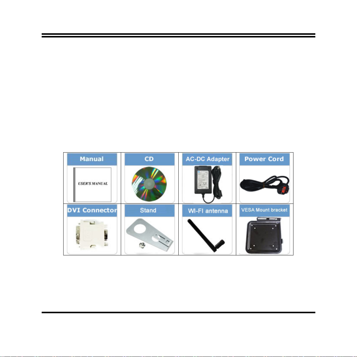
Package Contents
ii
Page 3

Safety Instruction
Operate the product according to the correct installation steps and with great care to make sure
safety and comfort using experience. Please refer to the following safety instruction guide to avoid
danger of electric shock or fire. Abide by the previous safety instruction guide to use and maintain
the product and the hard disk to make sure of safe operating environment.
Please follow the instruction manual for operation guide.
The appropriate operating temperature ranges from 0 °C–35 °C (32 °F–95 °F)
The operation humidity for this product is 5% to 80% RH.
To avoid high temperature, please DO NOT overload the maximum power of the external power
supply while the system is consuming high voltage. Be aware of the maximum temperature
allowance of the power supply.
See to it that the product is not working near the water.
Always unplug power cable and other hardware cables from the system before cleaning.
Apply only dry cloth for cleansing the product.
Make sure that there is no heat source nearby when the product is working.
Make sure that the thermal louver of the product is not blocked.
Make sure to remove the power plug from the product when there is a thunder storm.
Please remove the power plug from the product when you are not going to use the product for a
long time.
Make sure to set up or use the product on a stable surface.
Make sure not to drop the product or strike it by any means.
Make sure not to move the product when the power is on.
Make sure not to step on the power cables and other cables or rest anything in them..
Please contact qualified technician for maintenance or repair.
Use only accessories and parts that are made by the qualified manufacturer.
iii
Page 4

TABLE OF CONTENT
USER’S NOTICE .......................................................................................................................ii
PACKAGE CONTENTS ............................................................................................................ii
SAFETY INSTRUCTION ...........................................................................................................iii
CHAPTER 1 BRIEF INTRODUCTION
1-1 PRODUCT FEATURES...............................................................................................1
1-2 SPECIFICATION.........................................................................................................4
1-3 PRODUCT DIAGRAM.................................................................................................5
CHAPTER 2 HARDWARE INSTALLATION
2-1 TO OPEN THE CHASSIS ...........................................................................................6
2-2 TO INSTALL MEMORY MODULE(S).........................................................................7
2-3 TO INSTALL HARD DISK DRIVE ..............................................................................8
2-4 TO INSTALL WIFI CARD............................................................................................10
2-5 TO INSTALL TV CARD...............................................................................................12
2-6 TO RESTORE REMOVABLE CHASSIS COVER ......................................................14
2-7 TO ASSEMBLE THE STAND.....................................................................................15
2-8 TO VESA MOUNT THE SYSTEM...............................................................................16
CHAPTER 3 I/O CONNECTION AND REMOTE CONTROL
3-1 REAR PANEL CONNECTION....................................................................................18
3-2 FRONT PANEL CONNECTION..................................................................................24
3-3 REMOTE CONTRL DIAGRAM...................................................................................25
3-4 FUNCTION DESCRIPTION OF THE REMOTE CONTROL.......................................26
CHAPTER 4 NEW VISION USER INTERFACE
4-1 TO INSTALL NEW VISION USER INTERFACE...........................................................29
4-2 TO ACTIVATE NEW VISION PROGRAM .....................................................................32
4-3 NEW VISION USER INTERFACE BASIC OPERATIONS ............................................33
APPENDIX............................................................................................................................52
iv
Page 5

Chapter 1 Brief Introduction
1.1 Product Features
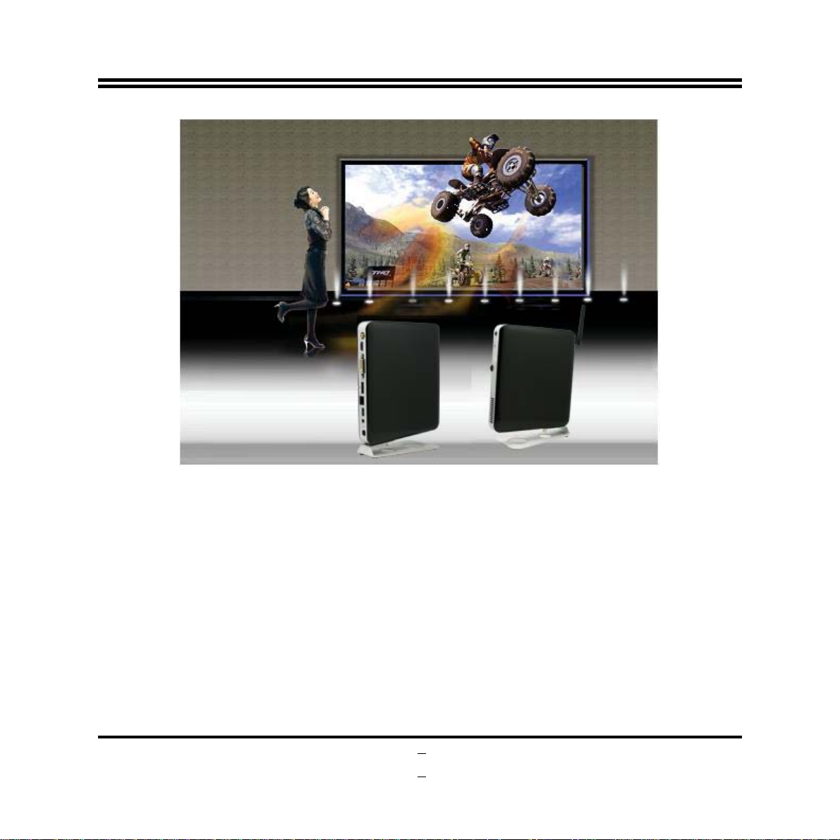
Thank you for purchasing the system, a new product developed, designed and manufactured under
leading technical power and consistent dedication to fine workmanship. The system provides you
HTPC enjoyment and stunning game-playing experience. It can also serves as home server for
data gather with its expandable Wi-Fi function.
This product has functions of general barebone systems, also a powerful system with competitively
advantage in:
HTPC Experience:
The system has both DVI and HDMI connector, supports optical SPDIF W/192KHz Audio output
and true 1080P high resolution video playback which ensures you brilliant video playback without
lag at the same time CPU usage rate is pretty low.
Game-Playing:
The system supports most online games and PC games with smooth playback better than that of
most average configured personal computer available on current market while CPU usage rate is
much lower.
Home Server:
The system can work as WiFi home server in the family with WiFi antenna attached. With this WiFi
network, computer in different rooms of the house can easily realize data sharing. You can easily
access to the downloaded HD movies stored in the HDD of the system, or watching other shared
videos stored in your PC via this function on high definition screen.
1
Page 6
The system has the following features besides other basic functions:
HDMI: The system comes with an HDMI output connector to realize full HD1080P high-definition
multimedia home theatre enjoyment. User can enjoy seamless playback of HD DVD and Blu-ray
disk in the living room by connecting system to LCD TV set with an HDMI cable for
non-compressed, full digital audio and video movie transmission.
SPDIF W/192KHz Audio output: The system supports optical SPDIF OUT 192KHz/24bit, auto
detecting peripheral devices and multi-streaming technology that transferring audio signals in
different directions. With this function you can enjoy playing games with multi-channel audio effect
on and talking to your friend with a microphone at the same time. It makes you feel that you were
right on the scene when you are watching HD movies with its multi-channel Hi-visual dramatic
audio output. All these thrilling functions can be realized with the system.
WiFi: the Mini PCI-E onboard socket in the board is integrated a with a WiFi card(802.11 b/g/n)
that can act as a mini wireless modem when external antennas are connected. Different
2
Page 7

computers in the house can build wireless connections through the Mini TOP system and take
necessary data from it, thus reducing the complexity in network establishment.
Giga LAN: The system is integrated with Gigabit LAN network controller with ACPI management
realizing efficient power management for the operating system.
USB2.0: The system supports USB 2.0 function compatible for both USB 2.0 devices and USB 1.1
interface devices. Users can enjoy high speed data transmission rate up to 480Mb/s. Users can
also connect USB 2.0 storage device to the system to create a data bank for storage of download
movies.
USB3.0: The system comes with USB 3.0 port for USB 3.0 function. User can experience fast data
transfers at 5Gb/s with the latest connectivity standard.
MMC/SD/MS 3 in 1 card reader: Users can easily insert the MMC/SD/MS card to the front panel 3
in 1 card reader to view the photos taken or video recorded. User can watch them through LCD TV
screen and make certain edition when it is shown. With a LCD TV you can realize better picture
quality for the video and photos.
CPU Usage: The CPU Usage diagram shows a beautiful data curve that indicate a pretty low CPU
usage percentage for 1080p HD video playback when running the system with a 24’’ LCD monitor
to play files of different formats, GPU performances are excellent as well.
dB Value: The design of the system takes into consideration the needed quiet operating
environment in the living room and the average dB value is below 26 under normal operation to
ensure the tranquility when you are absorbed in film watching.
Remote Control (Optional): The remote control makes it possible for users to power on/off and
switch from different functions with ease.
3
Page 8

1.2 Specification
AMD Fusion E350 Dual core APU
APU
Chipset
Memory Slots
Network
BIOS
Product Size
Front I/O port
Rear I/O port
Power Supply
Standard Accessories
Optional Accessories
Certificate
CPU Clock Speed: 1.6GHz
Radeon™ Brand : HD 6310 ( 492MHz )
AMD Hudson M1 Chipset
2 * SO-DIMM DDRIII Memory slots support 2 * SO-DIMM DDRIII 800/1066
memory modules up to 8GB
Integrated with Realtek Gigabit LAN chip
Mini-PCIE slot support 802.11b/g/n Wi-Fi card
AMI 16MB flash ROM
205(W)*185(D)*30(H)mm
1 * Power button/ power LED
1 * MIC connector and 1*Line-out/ Optical S/PDIF-out shared connector
2 * USB 2.0 ports
1 * card reader(SDC/MMC/MS)
1* Wi-Fi Antenna connector
1* HDMI + 1* DVI-I port
1 * E-SATA/USB 2.0 shared port
1 * RJ-45 LAN port
1 * USB 3.0 port
1 * 12V DC-in power connector
1 x TV tuner antenna hole
12V DC-in power supply
1 * 60W AC-DC Adapter
1 * power cord
1 * DVI-I to VGA convert adapter
1* stand and 1 * VESA mount bracket
WIFI antenna
1 * remote control
CE,FCC for barebone
CE,FCC,TUV,UL,CCC,CB for power adapter
Comply with Eup standards
Notice: The following diagrams and photos in the manual server as instruction purpose only and
may differ from actual product. Please refer to the product you purchase for actual specification.
4
Page 9
r
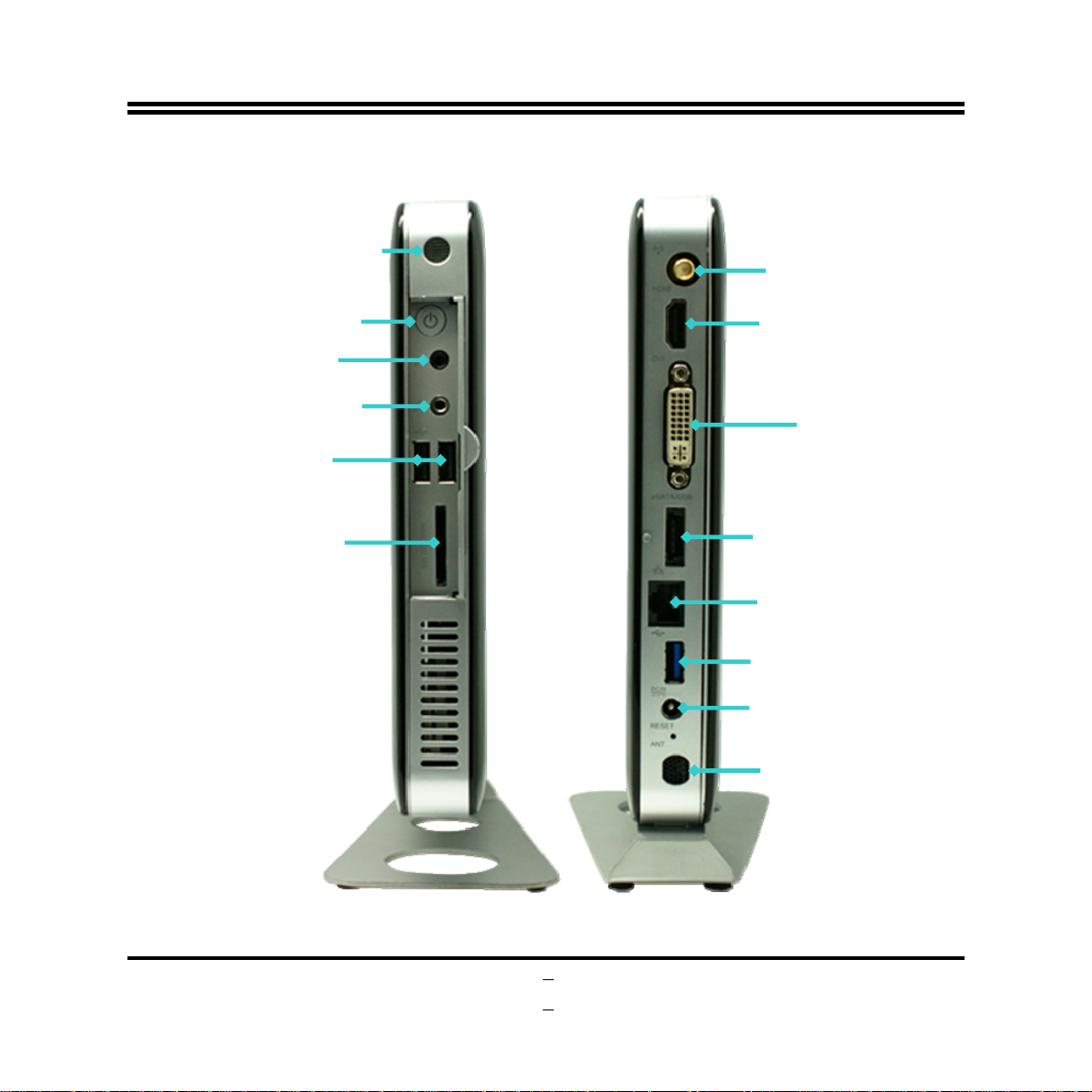
1-3 Product Diagram
Remote Sensor
Powe
Switch
Button
MIC
Line-out
/Optical SPDIF-out
USB 2.0 Ports
Card Reader Slot
Wi-Fi Antenna
Connector
HDMI Port
DVI-I Port
E-SATA /USB Port
RJ-45 Port
USB 3.0 Port
12V DC-in Jack
TV Tuner
Antenna Hole
Front Panel I/O Rear Panel I/O
5
Page 10
6
Chapter 2 Hardware Installation
WARNING! Please turn off the system and make sure that power cord is unplugged before
hardware installation to ensure safety.
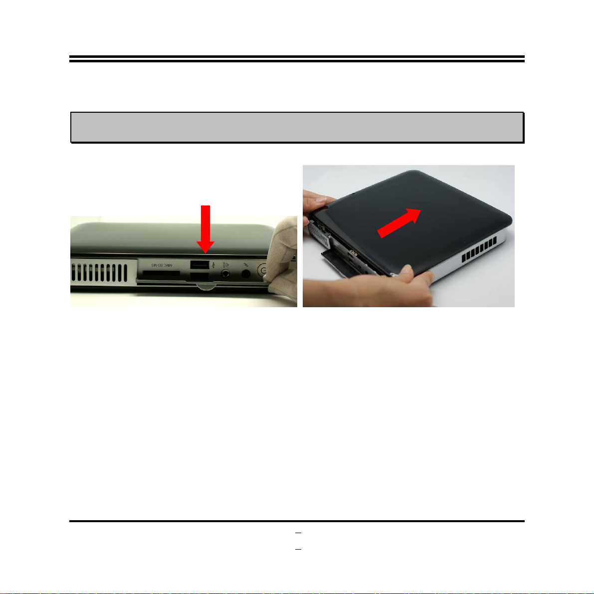
2.1 To Open the Chassis
1. Place the system on a flat surface and put the
side with removable cover upwards. Put
down the front panel I/O shield.
2. Push the removable panel in the direction
towards the back panel. You can easily open
the chassis in this way.
Page 11
7
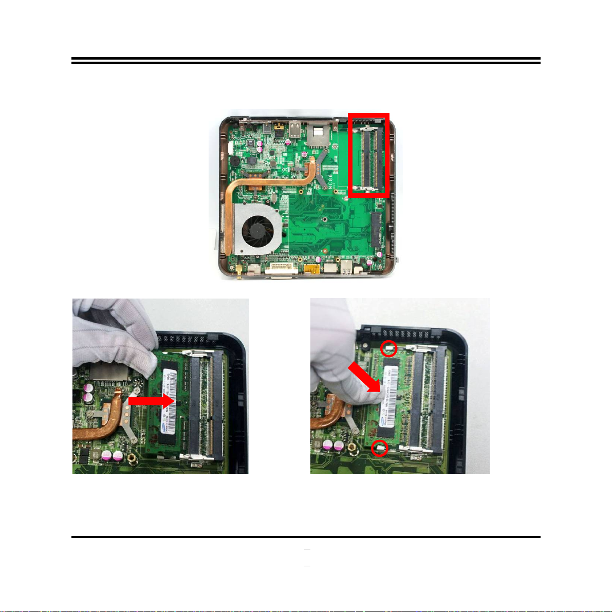
2.2 To Install Memory Module(s)
1. Locate the SO-DIMM memory slot(s) on the board.
3. Insert the gold-figure side of the compatible
DDRIII SO-DIMM into the slot at a 30
degree.
4. Press down as the photo shows. The eject
tabs will lock it if installed correctly.
Page 12
Notice:
When installing, align the notch on the module matches the break on the slot. Memory module
z
can only be installed in such a direction. If not, it will cause serious damage to module and the
board.
When you install memory module fully into the DIMM socket the eject tab should be locked into
z
the module very firmly and fit into its indention on both sides.
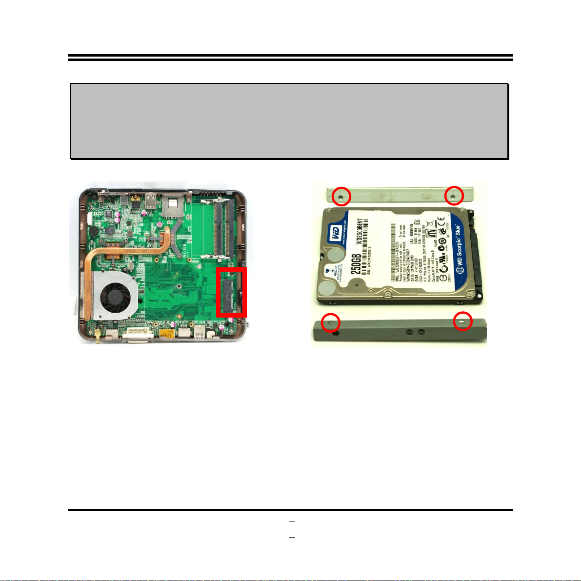
2.3 To Install Hard Disk Drive
1. Locate HDD connector on the motherboard
as the photo shows.
2. The SATA hard disk and the hard disk racks
(see to it that the marked screw holes on
rack and the corresponding holes on both
edges of HDD).
8
Page 13
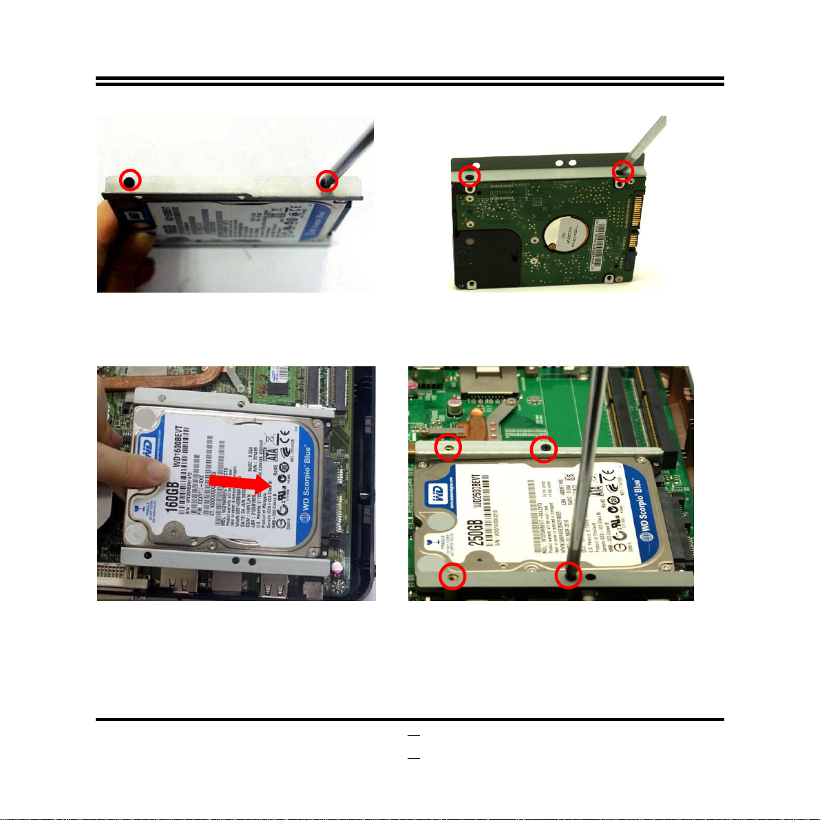
3. Lock the SATA hard disk to one of the racks
by tightening the screws in the marked
position.
5. Fit the hard disk into HDD connector on the
motherboard in this direction.
4. Lock the SATA hard disk to the other rack by
tightening the screws in the marked position.
6. Lock the racks to the board by tightening up
the screws in the marked position with a
screwdriver.
9
Page 14
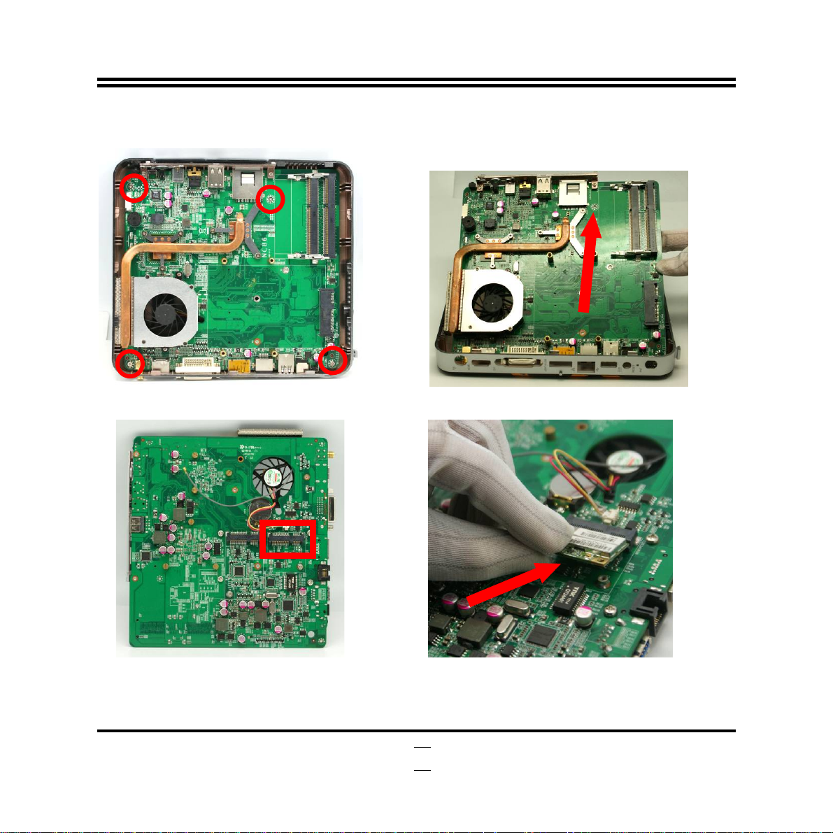
2.4 To Install WIFI Card
1. Remove the marked screws to unlock the
board from the chassis.
3. Turn the backside of the board upwards and
locate Mini-PCIE WI-FI card slot
(MIMIPCIE1).
2. Gently pick the board out of the chassis.
4. Insert the gold figure side of the compatible
Mini-PCIE WI-FI card into the Mini-PCI-E slot
by a 45 angle.
10
Page 15
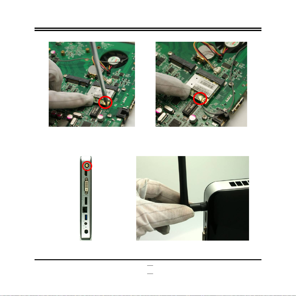
5. Tighten up the screw to make sure that the
card locked to the board.
*The above steps completed, please restore the board to chassis and close the chassis with the
removable cover (refer to 2.6).
6. Press the metal hat on the other end of the
antenna connector into the antenna slot
(ANT1) on card as shown.
7. Locate the RF slot for WIFI antenna
connector in the rear panel.
8. Connect the external WIFI receiver to the
antenna connector on the rear panel.
11
Page 16
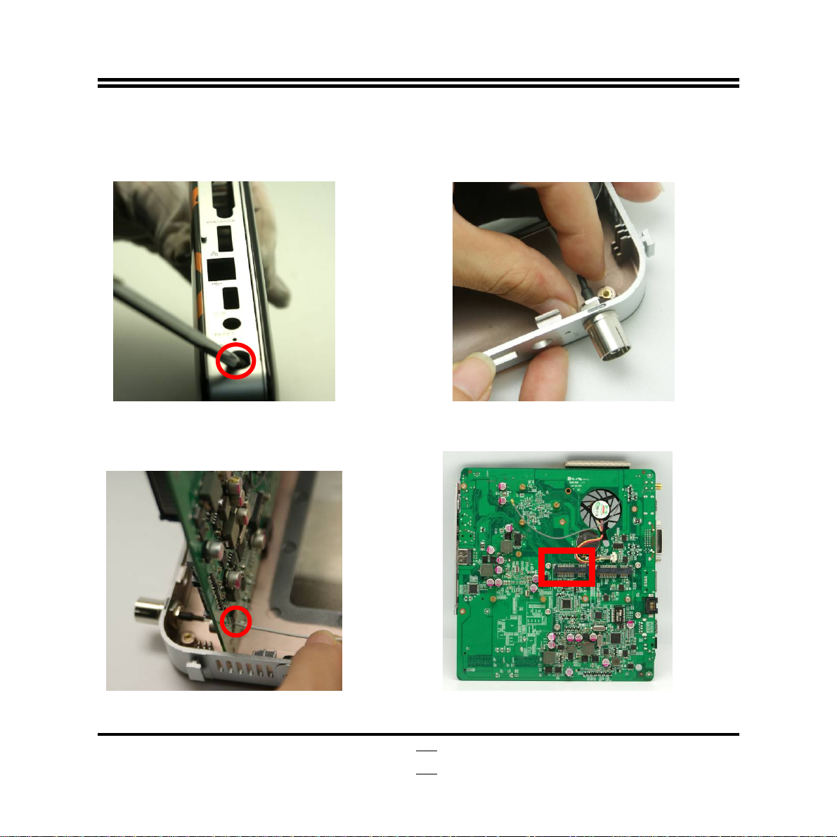
2.5 To Install TV Card
*The system also support TV card function. TV card slot is located near WIFI card slot. User also
needs to open the chassis and find the TV card slot before installation (please refer to 2.4).
1. Remove the TV antenna hole block net from
the chassis.
3. Push the antenna string into the reserved
hole of the board.
2. Push the antenna connector into TV antenna
hole and tighten one hexagonal bolt onto the
antenna connector to lock it to the chassis.
4. Turn the backside of the board upwards and
locate Mini-PCIE TV card slot (MIMIPCIE2).
12
Page 17
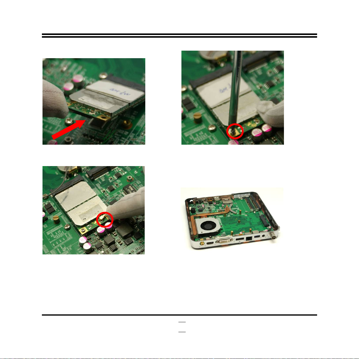
5. Insert the gold figure side of the compatible
Mini-PCIE TV card into the MIMIPCIE2 slot
by a 45 angle.
6. Tighten up the screw to make sure that the
card locked to the board.
7. Press the metal hat on the other end of the
antenna connector into the antenna slot on
card as shown.
*The above steps completed, please restore the board to chassis and close the chassis with the
removable cover (refer to 2.6).
8. Gently fit the board into its original place.
13
Page 18
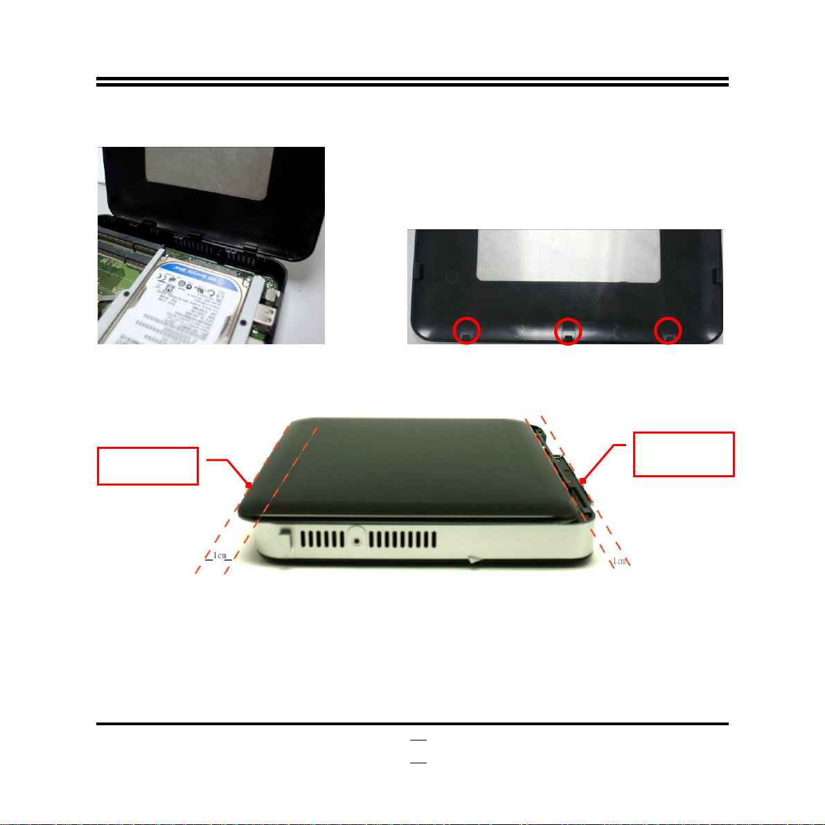
2.6 To Restore Removable Chassis Cover
1. Gently put the removable cover back to
the chassis
2. This edge with 3 plastic equidistant notches
should be parallel to edge of the chassis’ back
panel.
Front Panel
Back Panel
3. Place the removable cover upon the chassis. See to it that the left and right edges of the cover
should be parallel to those of the chassis and there should be a distance of about 1 cm left
between the front edge and the front panel of the chassis as the photo shows.
14
Page 19

4. Put the side of I/O back panel towards you and push the removable cover of the chassis in the
direction forwards.
2.7 To Assemble the Stand
1. See to it that the marked square space
fitted into the square notch on the chassis.
2. See to it that the marked tiny round space and
the screw hole in on the chassis are in the
same place.
15
Page 20

6
3. Lock the stand to the chassis by tightening up a
screw to the marked place.
2.8 To VESA Mount the System
1. Attach the chassis rack to the back of monitor by
tightening up the screws in the marked position.
4. The photo of the system with stand
installed.
2. See to it that the square notch on the
chassis is fitted into the marked square
space on the stand and marked notch
on the back panel of the chassis fitted
in the round space of the VESA mount
rack.
1
Page 21

7
3. The square notch on the chassis and the
square space on the stand.
4. Lock the chassis to the rack by tightening up
the screw in the marked position.
1
Page 22

Chapter 3 I/O Connection and Remote Control
After needed hardware installed inside the chassis, you can proceed on to connect cables to the
rear panel and power on the system to enjoy the using the system.
3.1 Rear Panel Connection
3.1.1. USB 3.0 Port
USB Cable
USB 3.0 port
USB Devices:
There are one USB 3.0 connector and one USB 2.0 /E-SATA shared connector (functions according to
device connected) on rear IO panel to connect USB mouse, keyboard and other USB storage devices
to the system. The blue one marked is USB 3.0 port.
Notice: Users can connect USB devices like MP3 player and USB mass storage device to the
system with USB cables. Some devices already have USB cables; user can just connect it to the
system directly.
USB Keyboard USB Mouse
MP3 Player
, etc …
18
Page 23

3.1.2. RJ-45 Port
RJ-45 LAN port
RJ-45 LAN Cable
Router Switch
The connector is standard RJ-45 connector for network. Please connect to the network cable to this
connector.
19
Page 24

3.1.3. ESATA/USB 2.0 Port
ESATA/USB 2.0port
ESATA Cable
ESATA Hard Disk
The function of this connector depends on different device connected to this connector through
different cable.
It could function as:
E-SATA connector when a compatible ESATA hard disk is connected to it through SATA cable.
USB 2.0 connector when a compatible USB device is connected to it through USB cable (for
device connection please refer to 3.1.1).
20
Page 25

3.1.4. DIV Port
DVI Port
DVI Cable
LCD Monitor
(Should come with DVI port)
This DVI (Digital Visual Interface) interface standard designed to maximize the visual quality of digital
display devices such as flat panel LCD computer displays and digital projectors.
21
Page 26

3.1.5. HDMI Port
HDMI Cable
LCD Monitor
(Should come with HDMI port for connection)
This point-to-point HDMI (High-Definition Multimedia Interface) interface is for audio and video signals
designed as a single-cable solution for home theater and consumer electronics equipment.
22
Page 27

3.1.6. DC-12V Power in Jack
Connect the DV power in end to the system, and plug the corresponding end of power cord to power
adapter and the other end to power socket. Then Turn on the system either by power switch on front
panel or remote control when all necessary configuration are made to power on the system.
Power cord Power adapter Power socket
23
Page 28

3.2 Front Panel Connection
Remote Sensor
Power on Switch W/
Power LED
MIC Connector
Line-out/SPDIF-out
shared Connector
USB 2.0 Port
Card Reader Slot
Card Reader Slot: to insert the MMC/SD/MS card to the front 3 in 1 card reader.
USB 2.0 Connectors: to connect USB mouse, keyboard and other USB storage devices to the system.
Line-Out /Optical SPDIF out shared Connector: this connector can function as ordinary audio
line-out connector or optical SPDIF out connector depending on different device connected to it:
Audio Line-out connector: by connecting stereo speakers or headphones.
Optical SPDIF out connector: by connecting 6-Channel HD Audio CODEC w/ SPDIF out audio
output device for superior audio enjoyment.
MIC Connector: User can connect microphone device to this port.
Power on Switch: after needed hardware installed and correct configuration made, you can power on
to enjoy multi-functions the system brings to you.
Remote Sensor: to receive instruction signal from remote control.
24
Page 29

3.3 Remote Control Diagram
The accessories of the system include a remote control with which you could easily carry out a lot
functions to bring you the friendly user-experience during HTPC watching, Karaoke, and other
functions.
25
Page 30

6
3.4 Function Description of the Remote Control
Icon Function Description
Press this button to power on/shut down the computer.
Power
Press to set computer into sleep mode.
STANDBY
The ‘ESC’ key on the keyboard.
ESC
Close the currently activated dialog box or task.
CLOSE
Opens the play DVD window in the Windows Media Center or opens
DVD MENU
the main menu or a DVD movie, if available.
Opens the Picture Library window in Windows Media Center.
PICTURES
Opens the Music Library window in Windows Media Center
Music
Opens the Videos Library windows in Windows Media Center.
VIDEO
Mouse Control PAD and left/right button.
Mouse
2
Page 31

7
This is to be used with mouse control buttons for drag operation.
lock
Press and hold “Lock” to select the object and move cursor at the
same time to desired position press again to un-lock.
The ‘Enter’ key on the keyboard.
OK
The direction key that control the cursor movement.
The magnifier functions under win7. If you want to close this function
Magnifier
must use the mouse to click the magnifier logo. Click again to close
the dialog.
Increase (+) and decrease (-) volume.
VOL +/-
Opens the Windows Media Center main menu.
Media Center
Changes the TV channels or moves page up and down, depending
on available options. Move to next DVD chapter.
PG(CH) +/-
The Media player control button group.
Windows common dialog step backward function button.
Back
2
Page 32

Windows common dialog forward function.
Forward
Opens internet explorer.
WWW
Full screen function button.
Full Screen
To delete selected function.
Delete
To fast return desktop button.
DeskTop
Press the Mic OSD button on remote control to invoke the
Mic OSD
on-screen-display Karaoke microphone/audio options during
Karaoke.
Windows select button, when multiple dialog boxes are open.
Windows Toggle
Mute
Turns off computer sound. The word ‘Mute’ is displayed when Mute
is turned on.
28
Page 33

Chapter 4 New Vision User Interface
After necessary hardwares installed and needed connections made, please install the
operating system and motherboard utility driver. There is also a ‘New Vision’ user
interface disk attached in the package, please find and install it afterwards to enjoy
more HTPC functions provided by the system!
New Vision provide quick platform for user to play video, music and games or browse
pictures easily.
4-1. To Install New Vision User Interface
Notice:
New Vision User Interface can only be run under 32-bit Windows Vista/7.
Double click the program ‘New Vision’ or right-click it then click ‘Open’ to activate the
program. A menu as below shall appear to ask you to select setup language. Choose
one then click ‘OK’ to begin installation.
29
Page 34

1. Click ‘Next’ on the welcom setup wizard
menu.
3. Click ‘Next’ to select a start menu folder. If
you would like to select a different folder,
click ‘Browse’.
2. Select destination location, then click ‘Next’.
4. Select the additional tasks you would like Setup to
perform while installing New Vision, then click ‘Next’.
30
Page 35

5. Click ‘Install’ to continue the installation, or click
‘Back’ if you want to review or change any
previous settings.
Notice!
Before you find the New Vision user interface program in the DVD that
comes with the system and install it in default destination location,
please install Windows operating system and motherboard driver.
6. Click ‘Finish’ to complete the setup. The
application may be launched by selecting the
installed icons.
31
Page 36

4-2.To Activate New Vision Program
Double click New Vision shortcut or right-click on it, then click ‘Open’ to activate New
Vision User Interface after installation completed. The following screen shall show up:
Click on the New Vision square frame to continue executing (User can use [Enter] on
keyboard or [OK] on remote control to enter as well). User shall do this in 11 seconds;
otherwise the program will exit automatically.
Notice!
Click Start/ Control Panel/ User Accounts and Family Safety/ User Account, and then
click Make Changes to your user account. The system will ask you to choose when
to be notified about changes to your computer. Pull the scrollbar to the end of the
pull-down menu so that system will Never Notify. Click OK and restart computer to
execute the settings.
32
Page 37

4-3. New Vision User Interface Basic Operations
As shown in the photo below, you will see New Vision main menu. Before explaining
the menu options, let’s learn the function keys first listed on the bottom part of the
screen.
• Press
direction key Up/Down
(↑/↓)on keyboard or remote control to select the
options you wish to confirm or make changes.
• Press
direction key Left (←)
on keyboard or remote control to return to previous
page.
• Press
[Delete]
on keyboard to delete the added programs, the default programs
cannot be deleted.
New Vision User Interface Main Menu
33
Page 38

4-3-1. To Play Video
Play Video: Select this option to play Video
Use direction key Up/Down (↑/↓) on keyboard or remote control to select ‘Play
Video’ on the main menu. Click [OK] on remote control (or the left button of the mouse,
or press [Enter] on keyboard) to confirm.
34
Page 39

When playing the video, use the following remote control buttons to change settings:
VOL+/-: Volume Up/Down; :Rewind ; : Forward; :
Play/Pause; :Replay; : Skip; : Stop.
Media Player: use Windows Media Player to playback video.
Video Libraries:playback video in Video Libraries of your system using user preset
media player.
DVD/CD: play video from DVD/VD. User should install DVD/CD into the optical disk
35
Page 40

6
drive in advance.
Removable Device:Playback video from removable devices. Press Up/Down to
select the desired removable device.
Return: Press Left key “←” on remote control or keyboard) to return to previous
page.
Notice!
Please make sure that the removable device is properly connected to
the system before playing video.
3
Page 41

7
4-3-2. To Play Music
Play Music: Select this option to play music.
Use Up/Down (↑/↓) button on remote control or keyboard to select ‘Play Music’ on the
main menu. Press [OK] on remote control (or click the left button of the mouse, or
press [Enter] on keyboard or) to confirm.
3
Page 42

Music Libraries:play music from Video Libraries of your system using user preset
media player
DVD/CD:play music from DVD/VD. Insert DVD/CD into the optical disk drive in
advance
Removable Device:Playback music from removable devices. Press Up/Down to
select the desired removable device.
Return:Press Left key “←” on remote control or keyboard) to return to previous page.
38
Page 43

4-3-3. To Browse Pictures
Browse Pictures: Select this option to browse pictures.
Press Up/Down (↑/↓) on remote control or keyboard to select ‘Browse Pictures’ on the
main menu. Click [OK] on remote control (or the left button of the mouse, or press
[Enter] on keyboard or) to confirm.
39
Page 44

Picture Viewer: browse pictures stored in the computer by Microsoft Picture Viewer
Media Player: use Windows Media Player to browse pictures.
Picture Libraries:Browse pictures listed in Picture Libraries of Windows system.
Removable Device:Browse pictures stored in desired removable device.
Return:Press Left key “←” on remote control or keyboard) to return to previous page.
40
Page 45

4-3-4. KARAOKE
KARAOKE: Enjoy the fun of Karaoke with interesting audio settings.
Press Up/Down (↑/↓) key on remote control or keyboard to select ‘KARAOKE’
function. Press [OK] on remote control (or the left button of the mouse, or [Enter] on
keyboard) to confirm. Set up and connect the equipped wireless microphone first
before using this function.
41
Page 46

Video Libraries:Find and play music video in Videos Libraries.
KARAOKE:Play music video/music in DVD/CD. Insert DVD/CD into the optical disk
drive in advance.
Removable Device:play music/music video in desired removable device.
Return:Press Left key “←” on remote control or keyboard) to return to previous page.
Delete: Press the DEL on keyboard to delete programs user added later to the menu
(the default programs cannot be deleted).
Mic OSD: Press the Mic OSD button on remote control to invoke the
on-screen-display Karaoke microphone/audio options during Karaoke.
Mic Onscreen Display has the following options:
42
Page 47

Mic Volume: increase or decrease the volume of MIC.
Mic Echo: increase or decrease the echo effect of MIC.
Mic Magic Voice: change MIC input voice into a desired magic voice.
Change Key: change the key of the music upward or downward to meet singer’s
desired key.
Vocal Cancellation: cancel vocal in the music or turn the vocal to background
play.
Reset: return to Mic OSD default settings.
Press remote control or keyboard key Up/Down (↑/↓) to select options on OSD, Left
(←) to decrease value, and Right(→) to increase value.Press [OK] on remote
control (or [Enter] on the keyboard) to enable or disable the selected options. Please
take notice that Mic Echo, Mic Magic voice, Change Key and Vocal Cancellation
functions are disabled as default settings. To enable these four options, user need to
connect equipped wireless microphone to the system and install needed sound
programs.
43
Page 48

4-3-5. Game Menu
Game Menu: Select this option to play game listed on game menu.
Press Up/Down (↑/↓) on remote control or keyboard or to select ‘Game Menu’ on the
main menu. Press [OK] on remote control (or the left button of the mouse, or press
[Enter] on keyboard) to confirm.
44
Page 49

The packaged New Vision software has no game program added to the list by default.
User shall add game programs as desired to the list through ‘Add Program’ option on
main menu. For more detail on how to add program please refer to 4-3-7.
45
Page 50

6
4-3-6. Other Program
Other Program:User can add programs to this list
Press Up/Down (↑/↓) on remote control or keyboard to select ‘Other Program’ on the
main menu. Press [OK] on remote control (or the left button of the mouse, or press
[Enter] on keyboard) to confirm.
4
Page 51

7
The default setting for New Vision has no program added to the list by default. User
shall add other programs as desired to the list through ‘Add Program’ option on main
menu. For more detail on how to add program please refer to 4-3-7.
4
Page 52

4-3-7. To Add Program
Add Program: Add programs to New Version User Interface
Press Up/Down (↑/↓) on remote control or keyboard to select ‘Add Program’ option.
Press [OK] on remote control (or the left button of the mouse, or press [Enter] on
keyboard) to confirm.
48
Page 53

The “Open” dialog window will automatically appear. Select the file you wish to add
from the dialog window. Click ‘Open’ to confirm the operation. Only programs
with .exe file extension can be added. You will see the following screen pop up for you
to decide where the .exe program to be added to.
49
Page 54

Press Up/Down (↑/↓) on remote control or keyboard to select desired destination for
the added program. For example, if you added ‘DVDMaker’ program to [Other
Program], a newly added option ‘DVDMaker’ will appear in [Other Program] menu list.
If you add it to ‘Game Menu’, it shall appear on the Game Menu list.
50
Page 55

4-3-8. To Exit
Press Up/Down (↑/↓) on remote control or keyboard to select ‘Play Music’ on the main
menu. Press [OK] on remote control (or the left button of the mouse, or press [Enter]
on keyboard) to confirm. You can exit New Vision program now.
51
Page 56

Appendix
General Notices
European Union CE Marking and Compliance Notices
Products intended for sale within the European Union are marked with the Conformity European (CE)
Making, which indicates compliance with the applicable Directive and European standards and
amendments identified.
Shielded Cables Notice
All connections to other computing devices must be made using shielded cables to maintain
compliance with FCC regulations.
Peripheral Devices Notice
Only peripherals (input/out devices, terminals, printers, etc) certified to comply with Class B limits may
be attached to this equipment. Operation with non-certified peripherals is likely to result in interference
to radio and TV reception.
Wireless Related Information
Wireless Interoperability
Wireless LAN PCI Express Mini Card is designed to be interoperable with any wireless LAN product
that is based on Direct Sequence Spread Spectrum (DSSS), Complementary Code Keying (CKK),
and/or Orthogonal Frequency Division Multiplexing (OFDM) radio technology, and is compliant to:
The IEEE802.11a/b/g/n Standard on Wireless LANs was defined and approved by the Institute of
Electrical and Electronics Engineers.
The Wireless Fidelity (WiFi) certification as defined by the Wi-Fi Alliance.
Usage Environment and Your Health
Wireless LAN PCI Express Mini Card emits radio frequency electromagnetic energy like other radio
devices. However, the level of energy emitted is far much less than the electromagnetic energy emitted
by wireless devices like for example mobile phones.
Due to the fact that Wireless LAN PCI Express Mini Card operates within the guidelines found in radio
frequency safety standards and recommendations, we believe the integrated wireless cards are safe
52
Page 57

for use by consumers. These standards and recommendations reflect the consensus of the scientific
community and result from deliberations of panels and committees of scientists who continually review
and interpret the extensive research literature.
In some situation or environment, the use of Wireless LAN PCI Express
Mini Card may be restricted by the proprietor of the building or responsible representatives of the
organization. These situations may for example include:
Using the integrated wireless cards on board of airplanes, or in hospitals
In any other environment that the risk of interference to other devices and service are perceived or
identified to be harmful.
If you are uncertain of the policy that applies on the use of wireless devices in a specific organization
(e.g., airport or hospital), you are encouraged to ask for authorization to use Wireless LAN PCI Express
Mini Card prior to turning on the computer.
Electronic Emissions Notices
European Union Compliance Statement Class B Compliance
European Union – Compliance to the Electromagnetic Compatibility Directive
This product is in conformity with the protection requirements of EU Council Directive 2004/108/EC on
the approximation of the laws of the Member States relating to electromagnetic compatibility. We
cannot accept responsibility for any failure to satisfy the protection requirements resulting from a
non-recommended modification of the product, including the installation of option cards from other
manufacturers.
This product has been tested and found to comply with the limits Class B Information Technology
Equipment according to European Standard EN55022. The limits for Class B equipment were derived
for typical residential environments to provide reasonable protection against interference with licensed
communication devices.
Properly shielded and grounded cables and connectors must be used in order to reduce the potential
for causing interference to radio and TV communications and to other electrical or electronic
53
Page 58

equipment.
FCC Rules and Regulations-Part 15
This devices uses, generates and radiates radio frequency energy. The radio frequency energy
produced by this device is well below the maximum exposure allowed by the Federal Communications
Commission (FCC)
z This device complies with the limits for the Class B digital device pursuant to Part 15 subject to the
following two conditions:
z This device may not cause harmful interference.
z This device must accept any interference received, including interference that may cause
undesired operation.
The FCC limits are designed to provide reasonable protection against harmful interference when the
equipment is installed and used in accordance with the instruction manual and operated in a
commercial environment. However, there is no guarantee that interference will not occur in a particular
commercial installation, or if operated in a residential area.
If harmful interference with radio or television reception occurs when the device is turned on, the user
must correct the situation at the user’s own expense. The user is encouraged to try one or more of the
following corrective measures:
z Re-orient or relocate the receiving antenna.
z Increase the separation between the equipment and receiver.
z Connect the equipment into an outlet on a circuit different from that on which the receiver is
connected.
z Consult the dealer or an experienced radio/TV technician for help.
CAUTION: The Part 15 radio device operates on a non-interference basis with other devices
operating at this frequency. Any changes or modification to said product not expressly approved by
Intel could void the user’s authority to operate this device.
54
 Loading...