

Page 1

CATALOGUE
1. AD2COM-PB ............................................................................. 1
2. AD4COMB-PB .......................................................................... 2
3. AD4COM-PB ............................................................................. 6
4. AD1RTLANP-LF / AD1RTLANG-LF .......................................... 7
5. AD3RTLANP-LF / AD3RTLANG-LF .......................................... 8
6. ADPCM2-PB / ADPCM-PB ........................................................ 9
7. ADCF ........................................................................................ 10
8. AD12VC-PB .............................................................................. 11
9. AD7DLV-LF ............................................................................... 12
10. AD7LVCOM-PB ........................................................................ 16
11. ADPE4S-PB .............................................................................. 20
12. AD9CRT2LAN-PB ..................................................................... 24
13. AD9CRT4C2L-PB ..................................................................... 25
14. AD9LV4COM-PB ...................................................................... 29
15. AD9DHDMI-PB.......................................................................... 36
16. AD8DVI-PB ............................................................................... 37
17. AD3INLANG-PB ........................................................................ 38
18. AD1INLANG-LF. ....................................................................... 39
19. AD8TV-PB................................................................................. 40
20. ADMPCIA-PB ................................ ................................ ............ 41
21. AD12VD-PB .............................................................................. 42
22. AD4COMC1-LF ......................................................................... 44
23. AD4COMCB-LF ........................................................................ 45
24. ADE24LV-LF ............................................................................. 46
25. ADX24LV4C-LF ........................................................................ 49
26. ADMPEOX4CA ......................................................................... 56
27. ADMPEISLA ............................................................................. 60
28. ADMPEIDLA ............................................................................. 63
29. ADMPEASU3A.......................................................................... 66
30. ADMPEASS3A .......................................................................... 69
G03-MINI-ITX-AD-F V8.0
Page 2
1
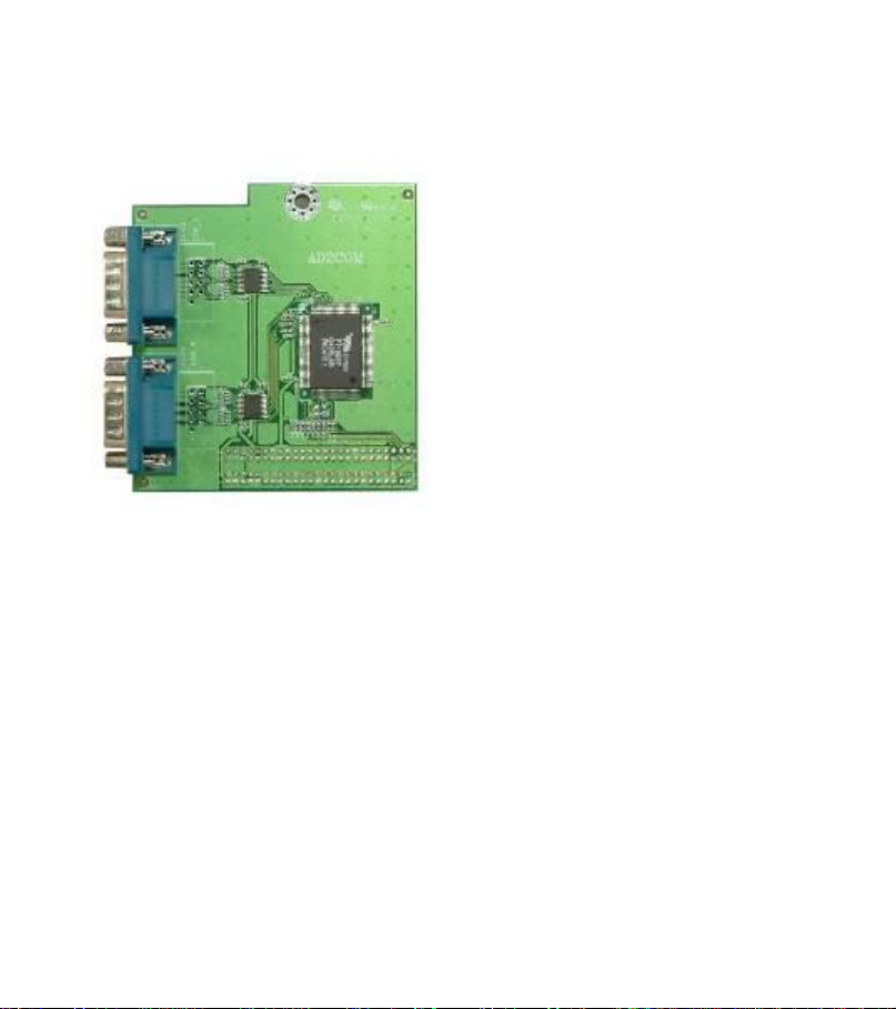
AD2COM-PB
Mini-ITX Two serial ports Adapter
Dimension: 75 x 82 mm
Chipset: FINTEK F71805F
Features:
Two high-speed 16C550 compatible UART with 16-byte FIFOs
Fully programmable serial-interface characteristics
Baud rate up to 115.2K
Connectors: 2 serial ports (COM3 & COM4)
Page 3
2
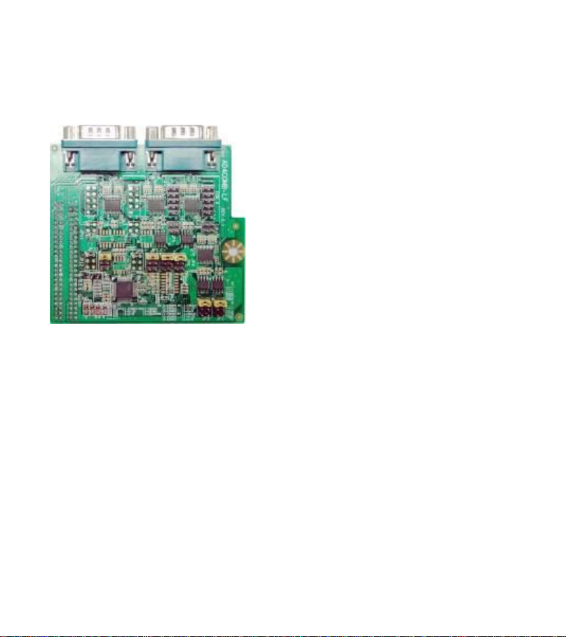
AD4COMB-PB
COM5
COM6
JP5
JP2
JP1
JP4
Four serial ports Adapter
Features:
Four high-speed 16C550 compatible UART with 16-byte FIFOs
Fully programmable serial-interface characteristics
Baud rate up to 115.2K
Support RS422/485 function
Connectors: 4 serial ports (COM3, COM4, COM5 &COM6)
Cable: Two COM port Connector Cable for connect COM_5 & COM_6
Headers and COM port Connectors
Page 4
3
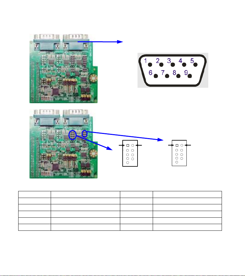
Part I .PIN DEFINITION
COM5
P
Pin1
Pin6
Pin6
Pin1
COM6
Pin No.
Pin Definition
Pin No.
Pin Definition
1
DCD
6
DSR
2
RXD
7
RTS
3
TXD
8
CTS
4
DTR
9
RI
5
GND
1. COM3&COM4
2.COM5&COM6
Pin Definition for COM3&COM4&COM5&COM6
Page 5
4
3. JP5&JP2
JP5
Pin1
Pin2
Pin1
Pin2
JP2
Pin No.
Pin Definition
Pin No.
Pin Definition
1
TXDP
2
TXDN
3
RXDP
4
RXDN
Pin No.
Pin Definition
Pin No.
Pin Definition
1
DATAP
2
DATAN
Pin Definition for JP5&JP2 when RS422 Selected
Pin Definition for JP5&JP2 when RS485 Selected
Page 6
5
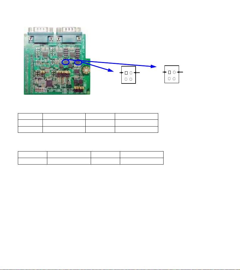
Part II Jumper setting to select RS 232/ RS 485/ RS 422 Function
I.Pin1&Pin2 in both JP6& JP4 closed to select RS232 for COM5,
Or Pin1&Pin2 in both JP3&JP1 closed to select RS232 for COM6.
Pin1
JP3
JP4
II.Pin3&Pin4 in JP6/JP3 closed to select RS485 Function for JP5 or JP2,
Pin3&Pin4 in JP4 /JP1closed to Enabled +12V for JP5 or JP2
III.Pin5&Pin6 in JP6/JP3 closed to select RS422 Function for JP5 or JP2,
Pin5&Pin6 in JP4/JP1 closed to Enabled +5V for JP5 or JP2
1-2:RS232
3-4:RS485
5-6:RS422
1-2:RS232
3-4:+12V
5-6:+5V
JP6
JP1
Pin1
JP6/JP3
JP1/JP4
JP6&JP4 is used to select RS 232/RS 485/ RS 422 Function for COM5&JP5
JP3&JP1 is used to select RS 232/RS 485/ RS 422 Function for COM6&JP2
Flow Control:
RS485 Control by RTS signal. Programmer should set RTS signal high before
sending data.
Page 7
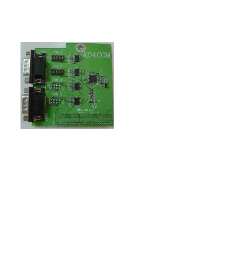
6
AD4COM-PB
Mini-ITX Four serial ports Adapter
Dimension: 92 x 82 mm
Chipset: FINTEK F81216DG
Features:
● Four high-speed 16C550 compatible UART with 16-byte FIFOs
Fully programmable serial-interface characteristics
Baud rate up to 115.2K
Connectors: 4 serial ports (COM3, COM4, COM5 &COM6)
Cable: Two COM port Connector Cable for connect COM_5 & COM_6
Headers and COM port Connectors
Page 8
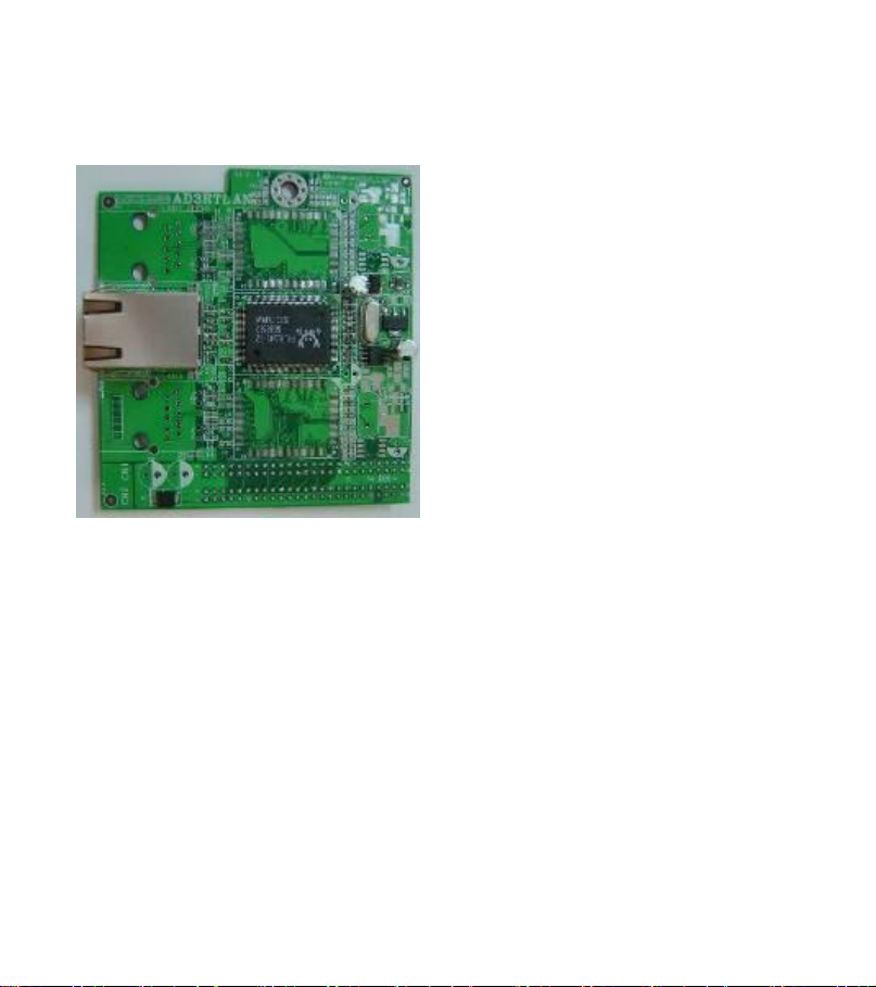
7
AD1RTLANP-LF / AD1RTLANG-LF
Mini-ITX LAN port Adapter
Dimension: 75 x 82 mm
Chipset: RealTek RTL8110S Giga-LAN for ADRTLAN-G
RealTek RTL8100C 10/100-LAN for ADRTLAN-P
Features:
● Integrated 10/100 transceiver for ADRTLAN-P
Integrated 10/100/1000 transceiver for ADRTLAN-G
● Supports PVI rev:2.3, 32bit, 33/66MHz
● Supports Full Duplex flow control (IEEE 802.3x)
● Fully compliant with IEEE 802.3, IEEEE802.3u, IEEE802.3ab
Connectors: one RJ45 LAN connector
Page 9
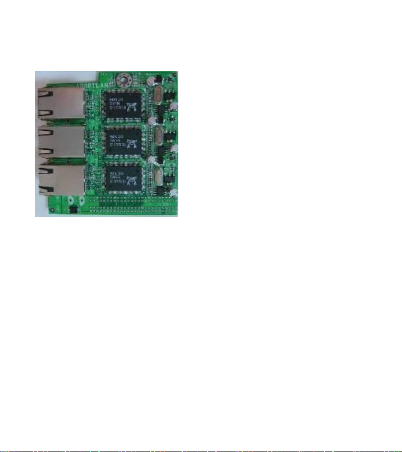
8
AD3RTLANP-LF / AD3RTLANG-LF
Mini-ITX three LAN ports Adapter
Dimension: 75 x 82 mm
Chipset: RealTek RTL8110S Giga-LAN for AD3RTLAN-G
RealTek RTL8100C 10/100-LAN for AD3RTLAN-P
Features:
● Integrated 10/100 transceiver for AD3RTLAN-P
Integrated 10/100/1000 transceiver for AD3RTLAN-G
● Supports PVI rev:2.3, 32bit, 33/66MHz
● Supports Full Duplex flow control (IEEE 802.3x)
● Fully compliant with IEEE 802.3, IEEEE802.3u, IEEE802.3ab
Connectors: three RJ45 LAN connectors
ATTENTION: Only suitable driver installed, these models (AD1RTLANG,
AD1RTLANP, AD3RTLANP, and ADPE4S) can work properly.
Page 10
9
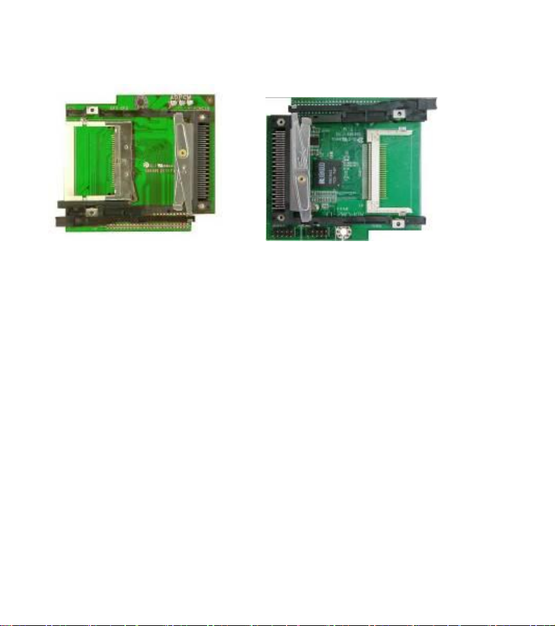
ADPCM2-PB / ADPCM-PB
Mini-ITX PCMCIA/ CF Adapter
ADPCM ADPCM2
Dimension: 90 x 82 mm
Chipset: RICOH R5C486 PCI-CARDBUS BRIDGE
Features:
- Support one 16-bit (PCMCIA2.1/ JEIDA4.2) card socket and one
CF(Compact Flash) socket
- PC 2001 Design Guide Compliant
- Compliant with PC card Standard Release 8.0 Specification
- 5 programmable memory windows and 2 programmable I/O windows
- Compliant with i82365SL compatible register set/ ExCA
- Power decreased by the improvement of Power Management
- Compliant with PVI Local Bus Specification 2.2
- Plug and Play support
Page 11

10
ADCF
Mini-ITX Compact Flash Adapter
Dimension: 75 x 82 mm
- Replacement for 3.5" hard disk drives
- Bootable device
- Behaves like an IDE disk, no special drivers required
- Plugs directly onto a 40 pin IDE connector
- Uses a floppy power connector
- Jumper configuration: master
- Not recommended for high vibration environments
- Jumper Setting: JP1
2-3 closed: CF power by 5V
4-5 closed: CF power by 3.3V
1-2 closed reserve (no function)
Page 12
11
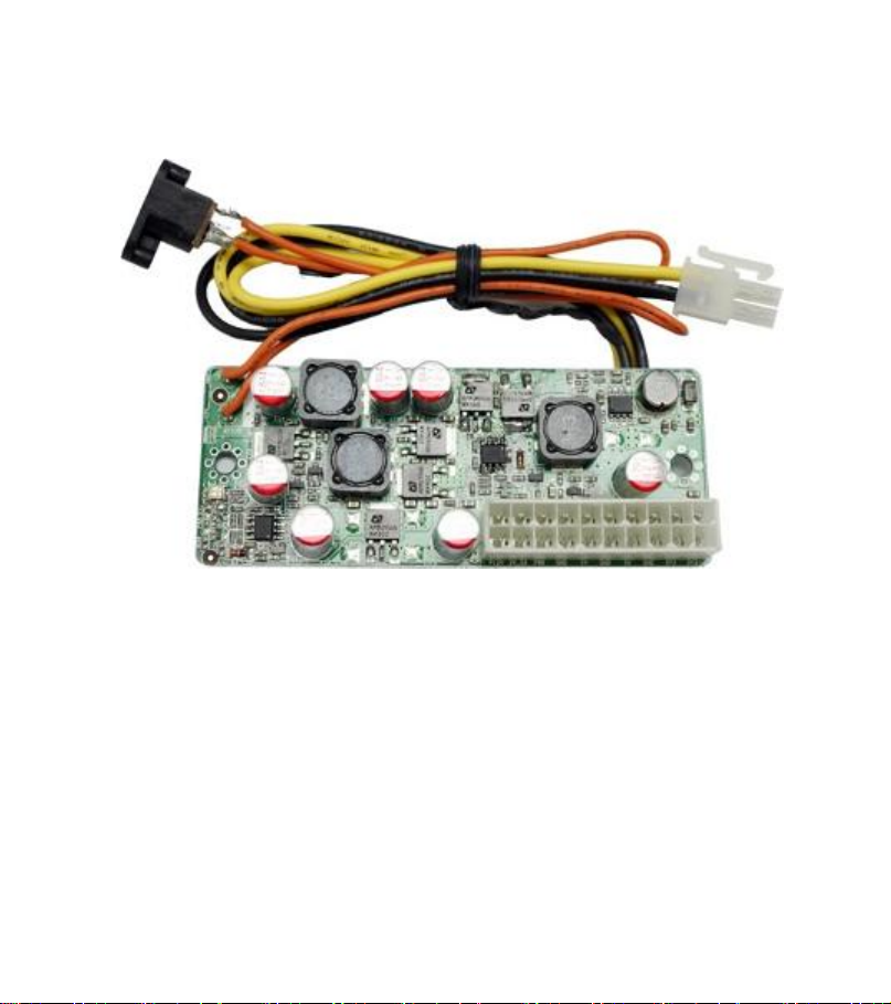
AD12VC-PB
12V Mini-ITX Power supply
Dimension: 160 x 45 mm
-100 Watt DC-DC power supply
- ATX standard compliant
- 12V operation
- 100% silent, small footprint
- Plugs directly into the motherboard ATX connector
Page 13
12
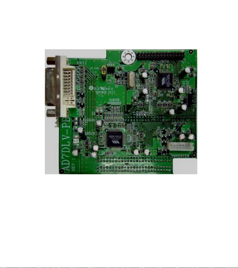
AD7DLV-LF
Mini-ITX 24-bit LVDS Panel Interface &DVI Port Adapt (For J7F2W
Series)
Dimension: 92 x 82 mm
Function:
- LVDS Panel Controller and DVI Connector
- VIA VT6136 Chip Supporting LVDS Signal for LVDS Panel
-VIA VT6132A Supporting DVI digital signal Output
Page 14
13
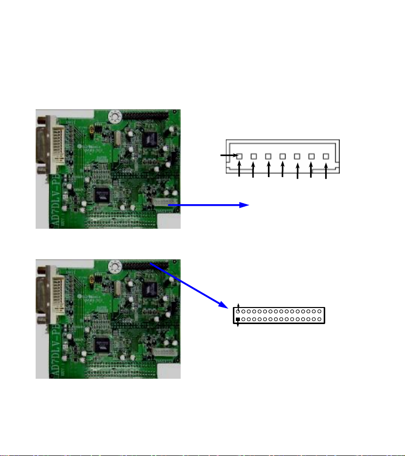
1. Inverter: LVDS Inverter headers
Pin 1
VCC
VCC
GND
GND
Backlight
GND
Brightness
Pin 1
24-bit LVDS Header
Pin 2
Pin 1 and pin2: VCC of inverter
Pin3、pin4 and pin6: GND
Pin5: Backlight
Pin7: Brightness
2. LCD (32 Pin): 24-bit LVDS header
Page 15
14
Pin No.
Pin Definition
Pin No.
Pin Definition
1
TXE3-
2
TXE3+
3
TXEC-
4
TXEC+
5
TXE2-
6
TXE2+
7
TXE1-
8
TXE1+
9
TXE0-
10
TXE0+
11
GND
12
GND
13
GND
14
GND
15
GND
16
GND
17
TXO3+
18
TXO3-
19
TXOC+
20
TXOC-
21
TXO2+
22
TXO2-
23
TXO1+
24
TXO1-
25
TXO0+
26
TXO0-
27
Pannel_VCC
28
Pannel_VCC
29
Pannel_VCC
30
Pannel_VCC
31
GND
32
GND
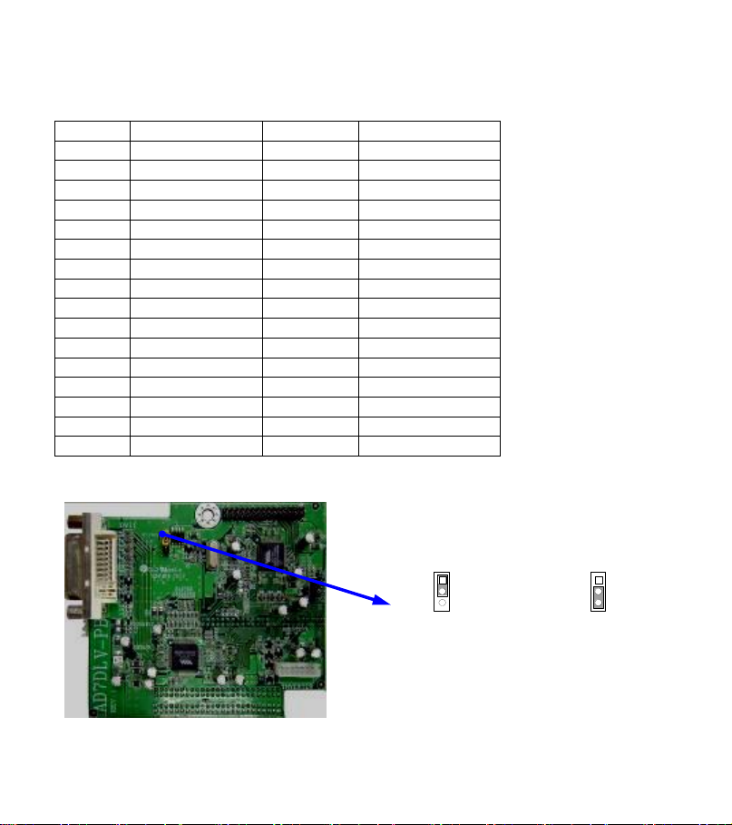
2-3 closed : PVDD= 3.3V
JP1
1
3
JP1
1
3
1-2 closed: PVDD= 5V
32 Pin Definition
4. JP1: LVDS 5V/3.3V Function setting (3-pin)
Page 16
15
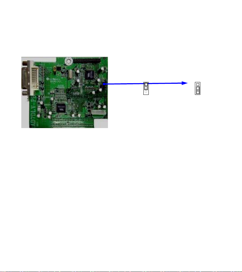
2-3 closed : backlight on
JP2
1
2
JP2
1
3
1-2 closed: backlight off
5. JP2: Panel backlight power on/off (3-pin)
Page 17
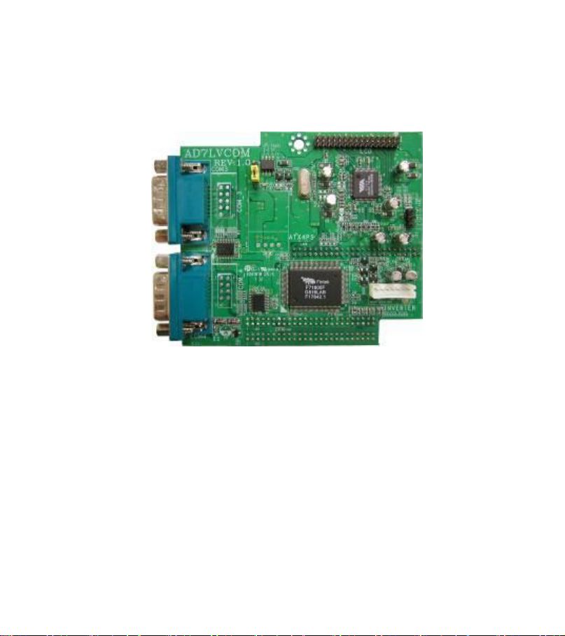
16
AD7LVCOM-PB
Mini-ITX 24-bit LVDS Panel Interface & COM Ports Adapt (For J7F2W
Series)
Dimension: 92 x 82 mm
Function:
- 24-bit LVDS Panel Controller and Serial Port
- VIA VT6136 Chip Supporting LVDS Signal for LVDS Panel
Chipset: FINTEK F71805F
Features:
Two high-speed 16C550 compatible UART with 16-byte FIFOs
Fully programmable serial-interface characteristics
Baud rate up to 115.2K
Connectors: 2 serial ports (COM3 & COM4)
Page 18
17
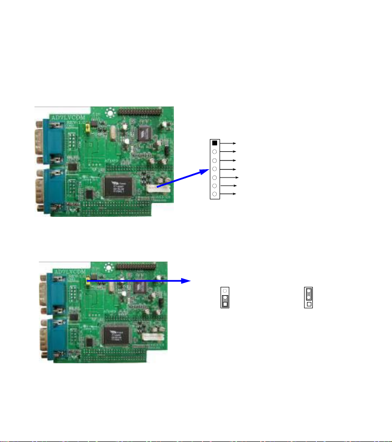
1. Inverter: Inverter Control Signal connector
+12V
+12V
GND
GND
Backlight
GND
Brights
Pin 1
Pin 7
Inverter Connector
2-3 closed : PVDD= 3.3V
JP1
3
1
JP1
3
1
1-2 closed: PVDD= 5V
Pin#1&Pin#2: +12V
Pin#3, Pin#4 &Pin#6: GND
Pni#5: LCD Back Light ON/OFF Control
Pin#7: LCD Panel Brightness Control
2. JP1:
1-2 closed: +5V Panel Signal Voltage
2-3 closed: +3.3V Panel Signal Voltage
LVDS 5V/3.3V Function setting (3-pin)
Page 19
18
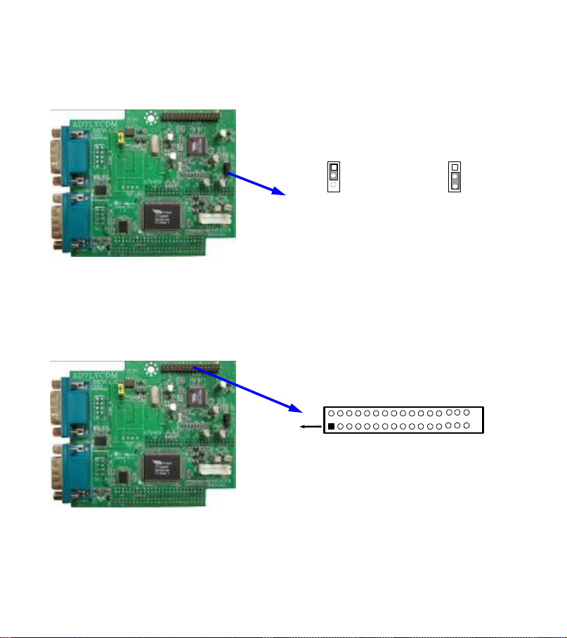
3. JP2 (only for PCB ver: 0.2): Panel backlight power on/off (3-pin)
24-bit LVDS Header
Pin 1
2, 4, 6, 8,10 …….. 32
1, 3, 5, 7,9 …….. 31
2-3 closed : backlight on
JP2
1
2
JP2
1
3
1-2 closed: backlight off
1-2 closed: OFF
2-3 closed: ON
Note: JP2 only for PCB rev: 0.2 please check the character which below the
COM4 connector it has “V:0.2”, if it is “V:0.1” did not have JP2 connector
4. LCD (32 Pin): 24-bit LVDS header
Page 20

19
1. 32 Pin Definition
Pin No.
Pin Definition
Pin No.
Pin Definition
1
TXE3-
2
TXE3+
3
TXEC-
4
TXEC+
5
TXE2-
6
TXE2+
7
TXE1-
8
TXE1+
9
TXE0-
10
TXE0+
11
GND
12
GND
13
GND
14
GND
15
GND
16
GND
17
TXO3+
18
TXO3-
19
TXOC+
20
TXOC-
21
TXO2+
22
TXO2-
23
TXO1+
24
TXO1-
25
TXO0+
26
TXO0-
27
Pannel_VCC
28
Pannel_VCC
29
Pannel_VCC
30
Pannel_VCC
31
GND
32
GND
Page 21
20
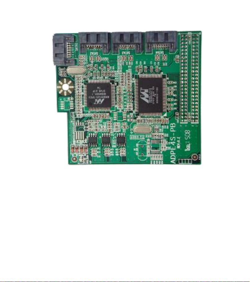
ADPE4S-PB
Raid Setting:
A. Motherboard: The IPC board with the 120-pin connector.
B. Daughter card: ADPE4S, SATA connector, support Raid.
Process:
1. Make the Raid Driver Floppy Disk. The floppy disk, CD, USB flash disk is ok when
the operating system is Vista.
Page 22

21
2.Boot-strap, when the following picture appears.
3. Press Ctrl+M key in to BIOS Setup interface.
4. Setting Raid mode, as follows.
Page 23

22
5. Quit after save it when the Windows installation interface appears, as follows
6. Press F6 before “Press F6 if you need to install a third party SCSI or RAID driver”
appears, then following interface will appear. It is no need pressing F6, just install
driver in the “Finding HDD interface” when the operating system is Vista.
Page 24

23
7. Press the key of S, input the floppy disk.
8. Choose the “Marvell 61xx SATA Controller 32bit Drive” or “Marvell 61xx SATA
Controller 64bit Driver” according the uses’ driver floppy disk program.
Page 25

24
AD9CRT2LAN-PB
Feature:
Support Intel secondly VGA port.
Support Two RealTek Giga-LAN port.
Ports: Two RJ45 LAN and one VGA port.
Page 26

25
AD9CRT4C2L-PB
Feature:
Support Intel secondly VGA port.
Support Two RealTek Giga-LAN port.
Support Three RS-232 serial ports.
Support One RS-232/422/485 serial ports.
Port:
Two RJ45 LAN and one VGA Port.
Connectors:
4 serial ports (COM1, COM2, COM3 &COM4(TX-RXCOM4))
Page 27

26
Part I .PIN DEFINITION
COM1
P
Pin6
Pin1
COM4
Pin1
Pin6
Pin1
Pin6
Pin1
Pin6
COM2
COM3
Pin No.
Pin Definition
Pin No.
Pin Definition
1
DCD
6
DSR
2
RXD
7
RTS
3
TXD
8
CTS
4
DTR
9
RI 5 GND
COM2
COM1
COM3
COM4
1 .COM1, COM2, COM3, COM4
in Definition for COM1&COM2&COM3&COM4
P
Page 28

27
2. TX-RXCOM4: RS-422 or RS485
RS422/485 Header
TX-RXCOM4
Pin 1
TXDN
RXDN
TXDP
2
RXDP
TX-RXCOM4
3-4 closed : +12V
JCOMP4
1
1-2 closed: RS232
1
1
5-6 closed : +5V
3. JCOMP4: RS232 Power Function Select
Page 29

28
4. JCOM4: RS232, RS485, RS422 Function select
3-4 closed : RS485
JCOM4
1
1-2 closed: RS232
1
1
5-6 closed : RS422
3-4 closed : +12V
JCOMP3
1
1-2 closed: RS232
1
1
5-6 closed : +5V
5. JCOMP3: RS232 Power Function Select
Page 30

29
AD9LV4COM-PB
Feature:
Support Intel secondly LVDS port.
Support Three RS-232 serial ports.
Support One RS-232/422/485 serial ports.
Page 31

30
1. LVDS1 Headers: LVDS1
Pin Number
Pin Define
Pin Number
Pin Define
Pin 1
LVDSB_DATA3-
Pin 2
LVDSB_DATA3+
Pin 3
LVDSB_CLK-
Pin 4
LVDSB_CLK+
Pin 5
LVDSB_DATA2-
Pin 6
LVDSB_DATA2+
Pin 7
LVDSB_DATA1-
Pin 8
LVDSB_DATA1+
Pin 9
LVDSB_DATA0-
Pin 10
LVDSB_DATA0+
Pin 11
DDC DATA
Pin 12
DDC CLOCK
Pin 13
Ground
Pin 14
Ground
Pin 15
Ground
Pin 16
Ground
Pin 17
LVDSA_DATA3+
Pin 18
LVDSA_DATA3-
Pin 19
LVDSA_CLK+
Pin 20
LVDSA_CLK-
LVDS1
Pin 1
LVDS1 Header
Pin 2
Page 32

31
Pin 21
LVDSA_DATA2+
Pin 22
LVDSA_DATA2-
Pin 23
LVDSA_DATA1+
Pin 24
LVDSA_DATA1-
Pin 25
LVDSA_DATA0+
Pin 26
LVDSA_DATA0-
Pin 27
PVDD
Pin 28
PVDD
Pin 29
PVDD
Pin 30
PVDD
Pin 31
Ground
Pin 32
Ground
Pin No.
Pin Definition
Pin No.
Pin Definition
1
DCD 6 DSR 2 RXD 7 RTS 3 TXD 8 CTS 4 DTR 9 RI
5
GND
COM1&COM2
2. Pin definition for COM1, COM2, COM3, COM4
Page 33

32
COM4
P
Pin1
Pin6
Pin1
Pin6
COM3
2-3 closed : PVDD= 3.3V
JP1
3
1
JP1
3
1
1-2 closed: PVDD= 5V
2. JP1: LVDS1 5V/3.3V Function setting (3-pin)
1-2 closed: Panel PVDD +5V Voltage
2-3 closed: Panel PVDD +3.3V Voltage
Page 34

33
2. JP2: Inverter1 VCC 12V/5V Function setting (3-pin)
2-3 closed : INVERTER 5V
JP2
3
1
JP2
3
1
1-2 closed: INVERTER 12V
3-4 closed : +12V
JCOMP3
1
1-2 closed: RS232
1
1
5-6 closed : +5V
3. JCOMP3: RS232 Power Function Select
Page 35

34
3-4 closed : +12V
JCOMP4
1
1-2 closed: RS232
1
1
5-6 closed : +5V
3-4 closed : 485
JCOM4
1
1-2 closed: RS232
1
1
5-6 closed : 422
4. JCOMP4: RS232 Power Function Select
5. JCOM4: RS232, RS485, RS422 Function select
Page 36

35
6. TX-RXCOM4: RS422/485 Header
RS422/485 Header
TX-RXCOM4
Pin 1
TXDN
RXDN
TXDP
2
RXDP
RX-TXCOM4
Pin 1
VCC
VCC
CC
GND
GND
GND
Backlight
Brightnes
sss
7. Inverter1: Pin-headers of LVDS Inverter
Pin 1 and pin2: VCC of inverter
Pin3、pin4 and pin6: GND
Pin5: Backlight
Pin7: Brightness
Page 37

36
AD9DHDMI-PB
Feature:
Support Intel DVI or HDMI port.
Port: One DVI Port
One HDMI Port
Page 38

37
AD8DVI-PB
DVI-D
Features:
Support VIA VX800 series only.
Connector: 1*DVI-D port.
Page 39

38
AD3INLANG-PB
Giga LAN Connectors
Feature
Integrated for 10/100/1000 Mb/s full-and half-duplex operation.
Wake on LAN * 3 support.
Low-latency transmit and receive queues.
Connector: Giga LAN Port x 3
Page 40

39
AD1INLANG-LF
Specifications
Onboard Intel 82541 PI PCI Giga LAN * 1
Feature
1. Onboard Intel 82541 PI PCI Giga LAN * 1
2. Integrated for 10/100/1000 Mb/s full-and half-duplex operation
3. Wake on LAN * 1 support
4. Low-latency transmit and receive queues
Application
1. Firewall
Interface
Jetway extend daughter card
Page 41

40
AD8TV-PB
S-Video Connector
RCA Video-out Connector
HDTV Connector
VGA Connector
Features:
Support VIA VX800 IC series only.
Connector: 1*VGA port; 1*HDTV connector; 1*S-Video connector; 1*RCA Video
connector.
Page 42

41
ADMPCIA-PB
Mini-PCI Slot
Slot: 1* mini-PCI slot.
Page 43

42
AD12VD-PB(120W DC/DC power module)
Function: 12Vdc input to ATX standard power supply.
Input characteristics
Page 44

43
Range: 12 Vdc +- 5%.
Output characteristics
Regulation
Ripple
Ripple &
Noise
Voltage
load range
min
max
max (mV)
max (mV)
Min
Max
+12V
0.5A
4A
-5%
+5%
100
125
-12V
0.1A
1A
-5%
+5%
150
5V
0.1A
8A
-5%
+5%
50
150
3.3V
1A
10A
-5%
+5%
50
75
5VSB
1A
2A
-5%
+5%
50
100
-5V
NA
NA
NA
NA
NA
NA
Current Max: 10A (max).
Environment
Operation temp. : 0-40 C.
Operation Relative Humidity: 20% - 90%.
Storage temp. : -20 – 60 C.
Storage Relative Humidity: 5% - 95%.
Vibration: 0.38mm; 5-55Hz.
Demission: 4X10 cm.
Page 45

44
AD4COMC1-LF
Dimension: 76 * 82 mm
Chipset: FINTEK F81216
Features:
Four high-speed 16C550 compatible UART with 16-byte FIFOs
Fully programmable serial-interface characteristics
Baud rate up to 115.2K
All of RS232s support powered function ( pin 9 )
Connectors: 4 serial ports (COM3, COM4, COM5 &COM6)
Cable: Two COM port Connector Cable for connect COM_5 & COM_6 headers and
COM port Connectors
IPC M/B Support: For All Series with Embedded PCI 100-Pin Adapter Conn.
Page 46

45
AD4COMCB-LF
Dimension: 76 * 82 mm
Chipset: FINTEK F81216
Features:
Four high-speed 16C550 compatible UART with 16-byte FIFOs
Fully programmable serial-interface characteristics
Baud rate up to 115.2K
All of RS232s support powered function ( pin 9 )
Support RS422/485 function
Connectors: 4 serial ports (COM3, COM4, COM5 &COM6)
Cable: Two COM port Connector Cable for connect COM_5 & COM_6 headers and
COM port Connectors
IPC M/B Support: For All Series with Embedded PCI 100-Pin Adapter Conn.
Page 47

46
ADE24LV-LF
Feature
Support 18 bit Single CH to 24 bit Single CH LVDS
Interface
Jetway extend daughter card
Application
Support 24 bit Single CH LVDS Panel Display
Jetway NC94FL & NC96FL & NF96FL series M/B supported
Page 48

47
1. LVDS1 pin header :
Pin Number
Pin Define
Pin Number
Pin Define
Pin 1
NC
Pin 2
NC
Pin 3
NC
Pin 4
NC
Pin 5
NC
Pin 6
NC
Pin 7
NC
Pin 8
NC
Pin 9
NC
Pin 10
NC
Pin 11
DDC_CLK
Pin 12
DDC_DATA
Pin 13
Ground
Pin 14
Ground
Pin 15
Ground
Pin 16
Ground
Pin 17
NC
Pin 18
NC
Pin 19
LVDS_CLK1
Pin 20
LVDS_CLK+
Pin 21
LVDSA_DATA2-
Pin 22
LVDSA_DATA2+
Pin 23
LVDSA_DATA1-
Pin 24
LVDSA_DATA1+
Pin 25
LVDSA_DATA0-
Pin 26
LVDSA_DATA0+
Pin 27
PVDD
Pin 28
PVDD
Pin 29
PVDD
Pin 30
PVDD
Pin 31
Ground
Pin 32
Ground
Pin 1
Pin 2
connect to M/B
Page 49

48
2. LVDS2 pin header :
Pin Number
Pin Define
Pin Number
Pin Define
Pin 1
NC
Pin 2
NC
Pin 3
NC
Pin 4
NC
Pin 5
NC
Pin 6
NC
Pin 7
NC
Pin 8
NC
Pin 9
NC
Pin 10
NC
Pin 11
DDC_DATA
Pin 12
DDC_CLK
Pin 13
Ground
Pin 14
Ground
Pin 15
Ground
Pin 16
Ground
Pin 17
LVDSA_DATA3+
Pin 18
LVDSA_DATA3-
Pin 19
LVDSA_CLK+
Pin 20
LVDSA_CLK-
Pin 21
LVDSA_DATA2+
Pin 22
LVDSA_DATA2-
Pin 23
LVDSA_DATA1+
Pin 24
LVDSA_DATA1-
Pin 25
LVDSA_DATA0+
Pin 26
LVDSA_DATA0-
Pin 27
PVDD
Pin 28
PVDD
Pin 29
PVDD
Pin 30
PVDD
Pin 31
Ground
Pin 32
Ground
Pin 1
Pin 2
connect to panel
Page 50

49
ADX24LV4C-LF
Feature
Support 18 bit Single CH to 24 bit Dual CH LVDS
Support 18 bit Single CH to 2 * 24 bit Single CH LVDS
Support 18 bit Single CH to 2 * 18 bit Single CH LVDS
Support two RS-232 serial ports (External)
Support two RS-232/422/485 serial ports (Internal)
Four high-speed 16C550 compatible UART with 16-byte FIFOs
Fully programmable serial-interface characteristics
Baud rate up to 115.2K
All of RS232s support powered function ( pin 9 )
Interface
Jetway extend daughter card
Application
Support 24 bit Dual CH LVDS Panel Display
Support 24 bit Single CH LVDS Panel Display
Support 18 bit Single CH LVDS Panel Display
Jetway NC9C & NF99 series M/B supported
Page 51

50
COM PORT SETTING :
P
COM3 & COM4
COM6
P
Pin1
Pin6
Pin1
Pin6
COM5
Pin No.
Pin Definition
Pin No.
Pin Definition
1
DCD 6 DSR 2 RXD 7 RTS 3 TXD 8 CTS 4 DTR 9 RI
5
GND
COM3 Port
COM4 Port
COM5 Header
COM6 Header
1. Pin definition for COM3, COM4, COM5, COM6
Page 52

51
2. COM3-T/ COM4-T/ COM5-T / COM6-T:RS232 Power Function Select
3-4 closed : +12V
1
1-2 closed: RS232
1
1
5-6 closed : +5V
COM3-T/COM4_T/ COM5_T /COM6_T Jumper Setting
COM3_T
COM4_T
COM6_T
COM5_T
.
Page 53

52
3. COM5_RS/COM6_RS: RS232, RS485, RS422 Function select
3-4 closed : 485
1
1-2 closed: RS232
1
1
5-6 closed : 422
COM5_RS/COM6_RS Function Select
COM5_RS
COM6_RS
.
Page 54

53
4. COM5_DT/COM6_DT: RS422/485 Header
COM-5 DT/ COM-6 DT
Pin 1
TXDP
2
TXDN
RXDP
RXDN
COM5_DT
COM6_DT
Page 55

54
LVDS SETTING:
Pin Number
Pin Define
Pin Number
Pin Define
Pin 1
LVDSB_DATA3-
Pin 2
LVDSB_DATA3+
Pin 3
LVDSB_CLK-
Pin 4
LVDSB_CLK+
Pin 5
LVDSB_DATA2-
Pin 6
LVDSB_DATA2+
Pin 7
LVDSB_DATA1-
Pin 8
LVDSB_DATA1+
Pin 9
LVDSB_DATA0-
Pin 10
LVDSB_DATA0+
Pin 11
DDC DATA
Pin 12
DDC CLOCK
Pin 13
Ground
Pin 14
Ground
Pin 15
Ground
Pin 16
Ground
Pin 17
LVDSA_DATA3+
Pin 18
LVDSA_DATA3-
Pin 19
LVDSA_CLK+
Pin 20
LVDSA_CLK-
Pin 21
LVDSA_DATA2+
Pin 22
LVDSA_DATA2-
Pin 23
LVDSA_DATA1+
Pin 24
LVDSA_DATA1-
Pin 25
LVDSA_DATA0+
Pin 26
LVDSA_DATA0-
Pin 27
PVDD
Pin 28
PVDD
Pin 29
PVDD
Pin 30
PVDD
Pin 31
Ground
Pin 32
Ground
Pin 2
Pin 1
1. LVDS1 pin header:
Page 56

55
2. SW1 ( LVDS type setting):
All Open:
SW1 Pin Close Status
2
Pin 1
1-3 Close:
3-4 Close:
5-6 Close:
SW1
SW1【all open or 1-3 close】:
1. LVDS support single or dual panel for 24 bit Single CH LVDS Panel
Display.
2. Resolution depend on BIOS setting maximum to 1280*1024.
SW1【3-4 close】:
LVDS support 24 bit Dual CH LVDS Panel Display。
SW1【5-6 close】:
LVDS support single or dual panel for 18 bit Single CH LVDS Panel Display.
Resolution supported should be depends on Panel actual Specification
ex. If panel resolution is 1280 * 1024 and need to display 800 * 480
resolutions, the display maybe not full screen; furthermore didn't display due
to panel not support the resolution.
ex. If panel resolution is 800 * 600 and need to display 1024 * 768 resolutions,
the display maybe not full screen; furthermore didn't display due to panel not
support such resolution.
Page 57

56
ADMPEOX4CA
Dimension:
30.00 x 50.95 mm
Chipset:
OXFORD - OXPCIe954 serial port controller
Feature:
– Support 3 * RS232 ports & 1* RS232/RS-422/RS-485
port
– Asynchronous baud rates up to 15Mbps
Interface:
Mini PCI-E
Accessories:
– 25cm COM cables W / Bracket * 2 sets
ADMPEOX4CA
Function
Illustration
Page 58

57
1. COM port pin header :
Pin Number
Pin Define
Pin Number
Pin Define
Pin1
-DCD1
Pin11
-DSR1
Pin2
SIN1
Pin12
-RTS1
Pin3
SOUT1
Pin13
-CTS1
Pin4
-DTR1
Pin14
-RI1
Pin5
GND
Pin15
Pin6
-DCD2
Pin16
-DSR2
Pin7
SIN2
Pin17
-RTS2
Pin8
SOUT2
Pin18
-CTS2
Pin9
-DTR2
Pin19
-RI2
Pin10
GND
OXTX-RXCOM
Pin 1
TXDP 2 TXDN
RXDP
RXDN
Pin 10
Pin 1
Pin 11
CN1, CN2
JP1
OXTX-RXCOM
2. RS485/RS422 :
Page 59

58
1-2 Close:
2
Pin 1
3-4 Close:
5-6 Close:
1-2 short
RS232
3-4 short
RS485
5-6 short
RS422
MPEOX4CA support quad series port ( port0~3).
※port 3 support multi function with RS232/485/422。
When RS485/422 , must change Hardware configuration to RS485
and Buffer enable to “ active high ”。
Step1:
Find the port3 device on the device management
Page 60

59
Step2:
1. Hardware configuration change to “ RS422/485 “
2. RS485 settings change to “ Active high “
Page 61

60
ADMPEISLA
Dimension:
30.00 x 50.95 mm
Chipset:
Intel-82574 GbE LAN controller
Feature:
Compliant with the 1Gb/s IEEE802.3/802.3u/802.3ab
Specifications:
– Support Full duplex operation at 10/100/1000 Mb/s;
– Support Half duplex at 10/100 Mb/s;
– Wake on LAN function (Mini PCI-E slot provides +
3VSB power supported);
– Support PXE Boot function
– Support 1 * Giga Lan
Interface:
Mini PCI-E
Accessories:
– 25cm 16P to 16P cable * 1 pcs
– GigaLAN Bracket * 1 set
Page 62

61
ADMPEISLA Function Illustration
Page 63

62
ADMPEISLA pin header:
Pin Number
Pin Define
Pin Number
Pin Define
Pin1
DD+
Pin2
3.3v power
Pin3
DD-
Pin4
3.3v power
Pin5
DC+
Pin6
LAN2_1000-
Pin7
DC-
Pin8
LAN2_LINK_ACT-
Pin9
DB+
Pin10
LAN2_100-
Pin11
DB-
Pin12
GND
Pin13
DA+
Pin14
GND
Pin15
DA-
Pin Number
Pin Define
Pin Number
Pin Define
Pin1
DD+
Pin2
3.3v power
Pin3
DD-
Pin4
3.3v power
Pin5
DC+
Pin6
LAN2_1000-
Pin7
DC-
Pin8
LAN2_LINK_ACT-
Pin9
DB+
Pin10
LAN2_100-
Pin11
DB-
Pin12
GND
Pin13
DA+
Pin14
GND
Pin15
DA-
Pin 15
Pin 1
Pin 2
LANCN
SLANCNA pin header:
Page 64

63
ADMPEIDLA
Dimension:
30.00 x 50.95 mm
Chipset:
Intel -i350 GbE LAN controller
Feature:
– Compliant with the 1Gb/s IEEE802.3, 802.3u,
802.3ab specifications;
– Support Full duplex operation at 10/100/1000 Mb/s;
– Support Half duplex at 10/100 Mb/s;
– Support Wake on LAN function (Mini PCI-E slot
provides + 3VSB power supported);
– Support PCI-E GEN1(2.5GT/s) , GEN2(5GT/s)
– Support 2 * Giga Lan
Interface:
Mini PCI-E
Accessories:
– 25cm 16P to 16P cable * 2 pcs
– Two GigaLAN Bracket * 1 set
Page 65

64
ADMPEIDLA Function Illustration
Page 66

65
ADMPEIDLA pin header:
Pin Number
Pin Define
Pin Number
Pin Define
Pin1
DD+
Pin2
3.3v power
Pin3
DD-
Pin4
3.3v power
Pin5
DC+
Pin6
LAN2_1000-
Pin7
DC-
Pin8
LAN2_LINK_ACT-
Pin9
DB+
Pin10
LAN2_100-
Pin11
DB-
Pin12
GND
Pin13
DA+
Pin14
GND
Pin15
DA-
Pin Number
Pin Define
Pin Number
Pin Define
Pin1
DD+
Pin2
3.3v power
Pin3
DD-
Pin4
3.3v power
Pin5
DC+
Pin6
LAN2_1000-
Pin7
DC-
Pin8
LAN2_LINK_ACT-
Pin9
DB+
Pin10
LAN2_100-
Pin11
DB-
Pin12
GND
Pin13
DA+
Pin14
GND
Pin15
DA-
Pin 15
Pin 1
Pin 2
LANCN1, LANCN2
LANCN1 ,LANCN2 :
DLANCNA pin header:
Page 67

66
ADMPEASU3A
Dimension:
30.00 x 50.95 mm
Chipset:
ASMedia - ASM1042 USB Host controller
Feature:
– Compliant with USB3.0 Specification Revision 1.0 ;
– Compliant with USB Specification Revision 2.0;
– Support PCI-E GEN1(2.5GT/s) , GEN2(5GT/s)
– Support 2 * USB2.0/USB3.0 port
Interface:
Mini PCI-E
Accessories:
– 25cm USB 3.0 cable W / Bracket * 1 set
ADMPEASU3A
Function
Illustration
Page 68

67
ADMASU3A pin header:
Pin Number
Pin Define
Pin Number
Pin Define
Pin1
USB3B_VCC
Pin19
USB3A_VCC
Pin2
USB3B_SSRX-
Pin18
USB3A_SSRX-
Pin3
USB3B_SSRX+
Pin17
USB3A_SSRX+
Pin4
GND-
Pin16
GND
Pin5
USB3B_SSTX-
Pin15
USB3A_SSTX-
Pin6
USB3B_SSTX+
Pin14
USB3A_SSTX+
Pin7
GND
Pin13
GND
Pin8
USB2B_D-
Pin12
USB2A_D-
Pin9
USB2B_D+
Pin11
USB2A_D+
Pin10
USB_OCA
Pin 1
Pin 10
Pin 11
USBCN1
Page 69

68
ATXPOWER_4P
Pin1
5VCC
Pin2
GND
Pin3
GND
Pin4
12V
Pin 1
Page 70

69
ADMPEASS3A
Dimension:
30.00 x 50.95 mm
Chipset:
ASMedia - ASM1061 SATA 6Gbps controller
Feature:
– Compliant with Serial ATA Revision3.0;
– Support PCI-E GEN1(2.5GT/s) , GEN2(5GT/s)
– Support IDE/AHCI mode.
– Support 2 * SATA2/SATA3 Port
Interface:
Mini PCI-E
Accessories:
– SATA3 50cm cable * 2 PCS
1-2 Close:
Pin 1
2-3 Close:
Pin 1
IDE mode
AHCI mode
ADMASS3A IDE/ACHI MODE SETTING:
 Loading...