

Page 1
.JET
EQUIPMENT& TOOLS
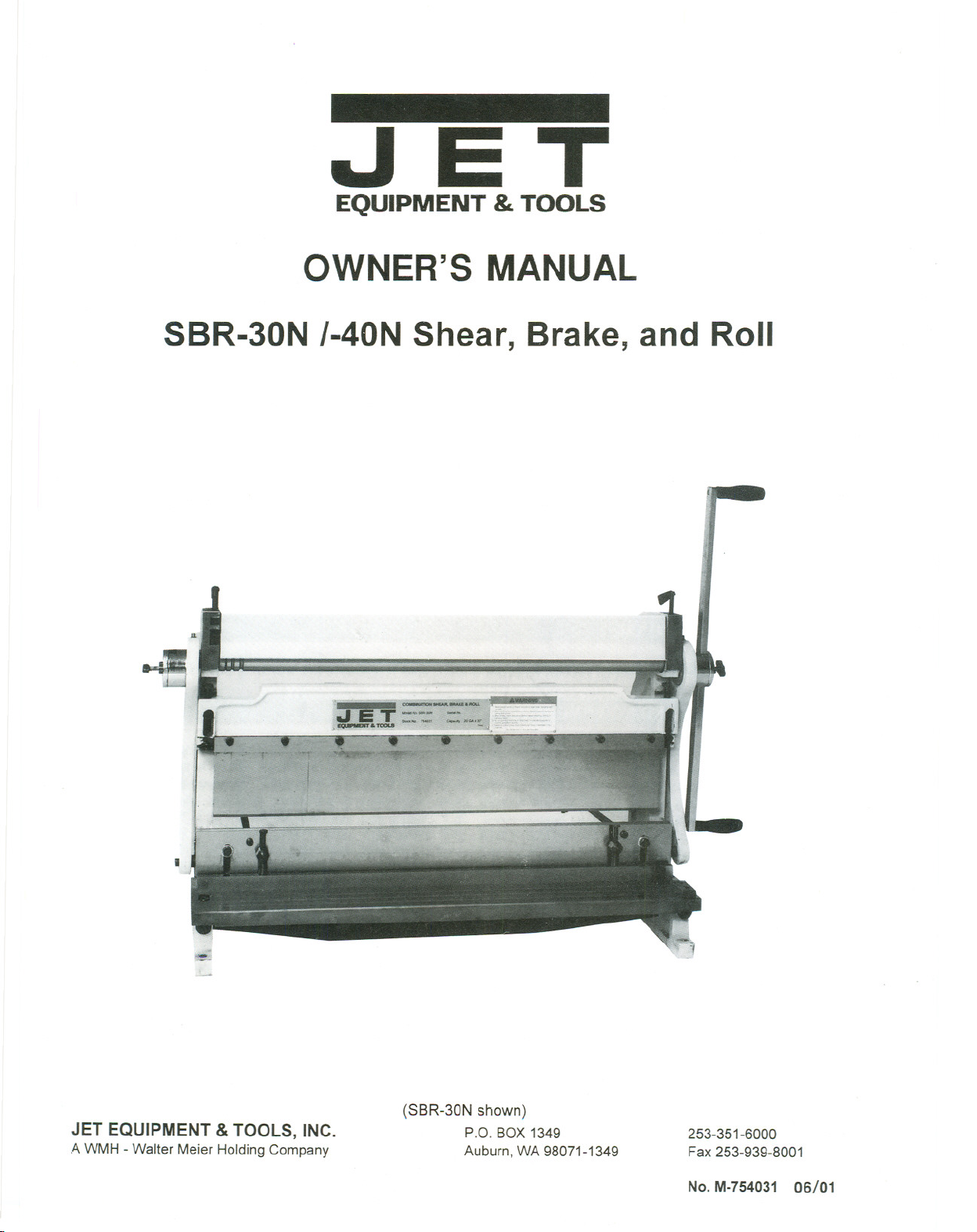
OWNER'S MANUAL
SBR-30N 1-40NShear, Brake, and Roll
~
.
JET EQUIPMENT &TOOLS, INC.
A WMH - Walter Meier Holding Company
.
~ ..ar.............
Ifill.,T -'" -.-.
.-' --'
,j,J
~ ..'-" ,.,./1";'1"
(SBR-30N shown)
P.o. BOX1349
Auburn,WA98071-1349
253-351-6000
Fax 253-939-8001
No. M-754031 06/01
Page 2
Important Information
1-YEAR
LIMITED WARRANTY
JET offers a one-year limited
warranty on this product
REPLACEMENT PARTS
Replacement parts for this tool are available directlyform JET Equipment& Tools.
To place an order, call 1-800-274-6848. Pleasehavethe following information ready:
1. Visa, MasterCard, or DiscoverCard number
2. Expirationdate
3. Part number listedwithin this manual
4. Shipping address other than a PostOffice box.
REPLACEMENT PART WARRANTY
JET Equipment & Tools makes every effort to assure that parts meet high quality and durability
standards and warrants to the original retail consumer/purchaser of our parts that each such
part(s) to be free from defects in materials and workmanship for a period of thirty (30) days from
the date of purchase.
PROOF OF PURCHASE
0
Please retain your dated sales receiptas proof of purchaseto validate the warranty period.
LIMITED TOOL AND EQUIPMENTWARRANTY
JET makes every effort to assure that its products meet high quality and durability standards and warrants
to the original retail consumer/purchaser of our products that each product be free from defects in materials
and workmanship asfollows: 1 YEAR LIMITEDWARRANTY ON THIS JET PRODUCT. Warranty does not
apply to defects due directly or indirectly to misuse, abuse, negligence or accidents, repairs or alterations
outside our facilities or to a lack of maintenance. JET LIMITS ALL IMPLIED WARRANTIES TO THE
PERIOD SPECIFIED ABOVE FROM THE DATE THE PRODUCT WAS PURCHASED AT RETAIL.
EXCEPT AS STATED HEREIN, ANY IMPLIED WARRANTIES OR MECHANTABILITY AND FITNESS ARE
EXCLUDED. SOME STATES DO NOT ALLOW LIMITATIONS ON HOW LONG THE IMPLIED
WARRANTY LASTS, SO THE ABOVE LIMITATION MAY NOT APPLY TO YOU. JET SHALL IN NO
EVENT BE LIABLE FOR DEATH, INJURIES TO PERSONS OR PROPERY OR FOR INCIDENTAL,
CONTINGENT, SPECIAL OR CONSEQUENTIAL DAMAGES ARISING FROM THE USE OF OUR
PRODUCTS. SOME STATES DO NOT ALLOW THE EXCLUSION OR LIMITATION OF INCIDENTAL OR
CONSEQUENTIAL DAMAGES, SO THE ABOVE LIMITATION OR EXCLUSION MAY NOT APPLY TO
YOU. To take advantage of this warranty, the product or part must be returned for examination, postage
prepaid, to an authorized service station designated by our Auburn office. Proof of purchase date and an
explanation of the complaint must accompany the merchandise. If our inspection discloses a defect, JET
will either repair or replace the product or refund the purchase price, if we cannot readily and quickly
provide a repair or replacement, if you are willing to accept such refund. JET will return repaired product or
replacement at JET's expense, but if it is determined there is no defect, or that the defect resulted from
causes not within the scope of JET's warranty, then the user must bear the cost of storing and returning the
product. This warranty gives you specific legal rights, and you have other rights, which vary, from state to
state.
JET Equipment &Tools. P.O.Box 1349,Auburn, WA 98071-1349 . (253) 351-6000
Page 3
&WARNING
.
Read and understand the entire instruction manual before attempting assembly or
operation.
.
This shear, brake, and roll is designed and intended for use by properly trained and
experienced personnel only. Ifyou are not familiar with the proper and safe operation
of a shear, brake, and roll, do not use until proper training and knowledge have been
obtained.
.
This shear, brake, and rollis intended to be used by one person only.
.
The shear, brake and rollmust be bolted securely to a stand and the stand bolted securely
to the floor. If the machine is to be bench mounted,the bench must be able to support the
weight of the machine and must be boltedto the floor.
.
Keepthe floor around the shear, brake,and roll clear of scraps, debris, oil, and grease. The
flooring around the machineshould bea non-skidtype.
.
Sheet metal stock has sharp edges.To preventcuts, use caution when handling.
.
Keep hands and fingers clear of the area in front and rear of the shearing blades.
.
Keep guards in place when not using the slip roll.
.
Keepother people away from the shear, brake, and roll.
.
Keep hands and fingers clear of the slip roll "nip" points. Keep handand fingers away from
the area in front andrear of the shear blades.
.
Keep hands and fingers away from the press brake dieswhen forming metal.
.
Do not exceed the maximum capacity of the machine.
.
Do not use the machinefor any purposeother than for which it is designed.
.
Failure to comply with all of these warnings may cause serious injury.
SOME DUST CREATED BY power sanding, sawing, grinding, drilling and other construction
activities contains chemicals known to cause cancer, birth defects or other reproductive harm. Some
examples of these chemicals are:
.
Lead from lead based paint
.
crystalline silica from bricks and cement and other masonry products, and
.
arsenic and chromium from chemically"treated lumber.
YOUR RISK FROM THOSE EXPOSURES varies, depending on how often you do this type of work.
.
To reduce your exposure to these chemicals:work in a well ventilated area, and work with approved
safety equipment, such as those dust masks that are specifically designed to filter out microscopic
particles
- 1 -
Page 4
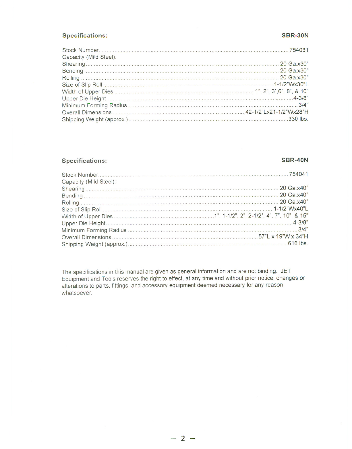
Specifications:
SBR-30N
Stock Number 754031
Capacity (Mild Steel):
Shearing 20 Ga.x30"
Bending ..20 Ga.x30"
Rolling 20 Ga.x30"
Size of Slip Roll 1-1/2"Wx30"L
Width of Upper Dies ' """""""""""""" 1",2",3",6",8", & 10"
Upper Die Height
Minimum Forming Radius 3/4"
..'" ... . " 4-3/8"
Overall Dimensions ... '... ... ... 42-1/2"Lx21-1/2"Wx28"H
Shipping Weight (approx.) ""'''''''''''' 330 Ibs.
Specifications:
Stock Number..........................
Capacity (Mild Steel):
Shearing.. """ ... ".. 20 Ga.x40"
Bending ' , " 20 Ga.x40"
Rolling , 20 Ga.x40"
Size of Slip Roll 1-1/2"Wx40"L
Width of Upper Dies 1",1-1/2", 2", 2-1/2", 4",7",10", & 15"
Upper Die Height .4-3/8"
Minimum Forming Radius 3/4"
Overall Dimensions 57"L x 19"W x 34"H
Shipping Weight (approx.) .616 Ibs.
'" 754041
SBR-40N
The specifications in this manualare given as general informationand are not binding. JET
Equipment and Tools reserves the rightto effect, at any time and without prior notice, changes or
alterations to parts, fittings, and accessory equipmentdeemednecessaryfor any reason
whatsoever.
- 2 -
Page 5
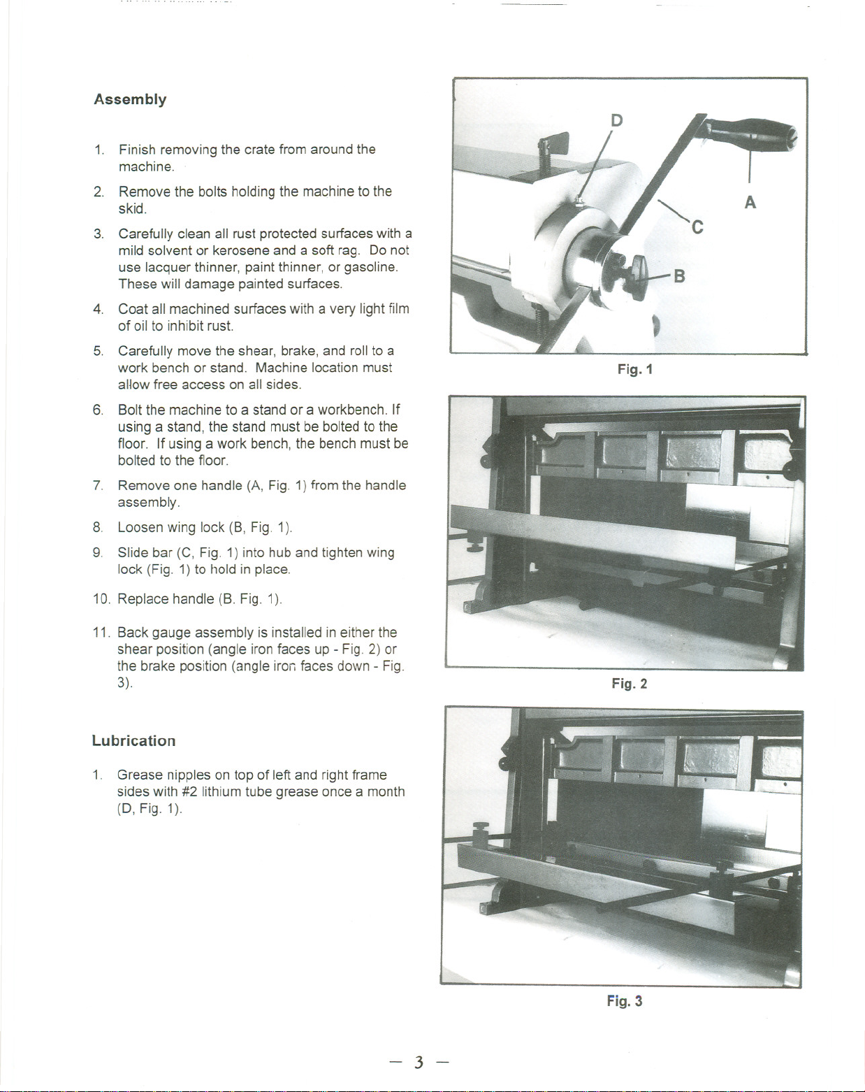
Assembly
1. Finish removing the crate from aroundthe
machine.
2. Removethe bolts holding the machineto the
skid.
3. Carefully clean all rust protected surfaceswith a
mild solvent or kerosene and a soft rag. Do not
use lacquer thinner, paint thinner, or gasoline.
These will damage paintedsurfaces.
4. Coat all machined surfaceswith a very light film
of oil to inhibit rust.
5. Carefully move the shear, brake, and roll to a
work benchor stand. Machine location must
allow free access onall sides.
6. Boltthe machine to a stand or a workbench. If
using a stand, the stand mustbe boltedto the
floor. If using a work bench, the bench must be
bolted to the floor.
7. Remove one handle (A, Fig. 1)from the handle
assembly.
8. Loosen wing lock (B, Fig. 1).
9. Slide bar (C, Fig. 1)into hub and tighten wing
lock (Fig. 1)to hold in place.
A
t
Fig.1
10. Replace handle (B. Fig. 1).
11. Back gauge assembly is installed in either the
shear position (angle iron faces up - Fig. 2) or
the brake position (angle iron faces down - Fig.
3).
Lubrication
1. Grease nipples on top of leftand rightframe
sides with #2 lithiumtube grease once a month
(0, Fig. 1).
Fig. 2
Fig. 3
- 3 -
Page 6

Setting Up the Press Brake
ateriallarger than 30" (40") 20
Failureto comply may cause
e to the machine!
To set up for bending:
1. Place a piece of wood 30" longon the bottom
die. This will support the upper die(s) during the
following adjustment.
2. Close the brake until the wood contacts the
upper dies.
3. Loosenhex cap socket retainingscrews (A, Fig.
4).
4. Select die(s) (8, Fig.4) for the desiredjob and
remove others.
5. Lower handle until the wood forcesthe dies to
seat uniformly in the upper beam.
6. Lock all clamp screws (A, Fig. 4) securely.
Fig. 4
~. ..--
To adjust the brake beam to make 90° bendsat the
bottom of the stroke:
1. Loosen locking screws slightly (A, Fig. 5).
2. Turn brake beam adjusting nuts (8, Fig. 5)
located on either end of the beam untiltest
bends reflect a 90° bend at both ends of the
brake.
3. Tighten locking screws (A, Fig. 5).
For special repetitive bends, the brake beam may be
adjusted to over-bend the desired angle since the
metalwill have some degreeof "spring back".
Setting Up the Shear
'!\ WARNING.
B
A
Fig. 5
1. Move the angle iron on the back gauge
assembly to the "up"positionif not already set
that way. (See Fig. 6)
Fig. 6
- 4 -
Page 7

2. Work to be sheared mustbe squared againstthe
squaring guide.
3.
Adjust the holddown to within 1/4"above the
table when the shear bladeis in the up position
by turning two hex cap bolts (A, Fig. 7). When
the blade starts it's downward travel, the hold
down should immediately hold the work piecein
place.
To prevent distortion, "snap"the handleto facilitate
piercing when notching.
To adjust lower shear:
1. Loosen two hex cap screws (8, Fig. 7) on each
end of the table.
2. Use adjusting screws (A, Fig. 8) to narrowthe
gap between the shear and the table to facilitate
cutting of thin material.
Setting Up the Slip Roll
'!\ WARNING
r than 30" (40") 20
.eel!
over the slip rolls
ng fed into the rolls!
cause serious injury
chinel
Hhe
ay
and/or hands!
If it doesn't interfere with the proposedfinal
Note:
shape or design, a slight bendmadewith the press
brake on the leadingedgewill simplify the initial
rolling process.
Fig. 7
- 5 -
Fig. 8
Page 8

Upper roll must havesufficient pressure on the work
piece to feed properly.
To remove cylindrical shaped workpieces:
1. Loosen wing screws (A, Fig. 9) on either of the
top roll.
2. Loosen hex socket cap screw (8, Fig.9)and
rotate toward the rear of the machineto release
roll catch.
3. Carefully grasp rolland pulltowardyou to
remove.
4. Once removed, cylindrical shapedwork pieces
may be slipped off the end of the roll.
Fig. 9
- 6 -
Page 9

g;
,...,
Breakdown for the SBR-30N Shear, Brake, and Roll
~ "
'"" /
//
~,//
"'<t '
U'\ /'
//
""'
~
"'"' ""'" /IV ,,'".:\
\ ~ ~-r
,.~~
;:R. ;;e ;;;:-
\ i <::><;:>
\/
\ Q ~
, -0-0
\
,~~ ~-' //
:;; /
~ . /
~V{
' I:C \"",
;:g ~,
~ I :fif
~
. J.n
,
1.<'\ "'it
",..,
~
.
t
~~
~ ./
.;'" /
/
//
/
/
~
~
- 7 -
Page 10

PartsListForTheSBR-30NShear,Brake,andRoll
Index
No.
1 SBR30N-1 Frame (left) 1
2 SBR30N-2 Table 1
3 SBR30N-3 Cross Beam 1
4 SBR30N-4 Arm (left) """""'''''''''''''''''''''''''''''''''''''''''''''''' 1
5 SBR30N-5 Frame (right) 1
6 SBR30N-6 Spacer Bar """"""""""""""""" 1
7 SBR30N-7 Cover 2
8 SBR30N-8 Plug 2
9 SBR30N-9 Spring 2
10 SBR30N-10 Press Plate 1
11 SBR30N-11 Cutter Plate 1
12-1 SBR30N-12-1 Brake Forming Die 10" 1
12-2 SBR30N-12-2 Brake Forming Die 8" 1
12-3 SBR30N-12-3 Brake Forming Die 6" 1
12-4 SBR30N-12-4 Brake Forming Die 3" 1
12-5 SBR30N-12-5 Brake Forming Die 2" 1
12-6 SBR30N-12-6 Brake Forming Die 1" 1
13 SBR30N-13 Press Plate 1
14 TS-1491081 Hex Cap BoiL M10x50 2
15 SBR30N-15 Pivot 2
16 SBR30N-16 Block 1
17 SBR30N-17 .. Adjustable Bolt 2
18 SBR30N-18 Handle Bar 1
19 SBR3ON-19 Guide Rod 2
20 SBR30N-20 Guide Block 2
21 SBR30N-21 '''''''''''''''' Guide Plate 1
22 SBR30N-22 Guide Bar 1
23 SBR30N-23 Cutter 2
24 SBR3ON-24 Roll """"'''''''''''''''''''''' 1
25 .SBR30N-25 . Screw 2
26 SBR30N-26 Handle 2
27 SBR30N-27 Adjustable Bolt. 2
28 SBR30N-28 ... Bushing 4
29 SBR30N-29 Cover 2
30 SBR30N-30 Gear '"'''''''''''''' 2
31 SBR30N-31 Lower Pressing Roll 1
32 SBR30N-32 Upper Pressing Roll 1
33 SBR30N-33 Cover 1
34 SBR30N-34 .'''''''''''''''''''''' Shaft 1
35 SBR30N-35 Eccentric Shaft 2
36 SBR30N-36 Washer 10.5 2
37 SBR30N-37 Arm (right) """ " 1
38 SBR30N-38 Key 2
39 TS-1482031
39A SBR30N-39 Lock BoiL 1
40 SBR30N-40 Hex Socket Cap Screw M6x10 2
41 TS-150506 Hex Cap BoiL M6x40 2
42 TS-150303 Hex Socket Cap Screw M6x12 1
Part
No.
Description
Size
Qty.
Hex Cap BoiL M6x12 4
- 8 -
Page 11

43 SBR30N-43 ThumbScrew 2
44 TS-1482031 HexCap Bolt M6x10 2
45 TS-150506 Hex Socket Cap Screw M1Ox40 2
46 ..SBR30N-46..., Washer ...... 10.5 2
47 TS-1492051 HexCap BoiL ... M12x50 1
48 TS-1492051 HexCap BoiL M10x20 2
49 SBR30N-46 .Washer 10.5 2
50 SBR30N-50 , Adjustable NuL M12 1
51 TS-1492041 HexCap Bolt M12x40 2
52 TS-1491051 HexCap Bolt M1Ox35 2
53 TS-1483031 HexCap Bolt M8x25 9
54 TS-1491031 HexCap Bolt M1Ox25 4
55 SBR30N-46 Washer 10.5 2
56 SBR30N-56 Hex Cap BoiL M8x90 2
57 TS-1482021 HexCap BoiL M6x10 7
58 ... TS-1482021 Hex Cap BoIL ~ M6x12 2
59 TS-1482021 HexCap BoiL . M6x12.,... 7
60 TS-1491031 HexCap Bolt , M1Ox25 2
61 SBR30N-61 Washer , 10.5 2
62 SBR30N-62 Hex Socket Set Screw M5x10 20
63 SBR30N-63 v- Block 5
64 SBR30N-64 Hex Nut M5 20
- 9 -
Page 12

Breakdown for the SBR-40N Shear, Brake, and Roll
:S!
~~
~ ,~~ ::\
\ i", '''r
\ Q-
, .-0-0
\
~
;R, "'" 0-
\ / <:::> C
'V
- 10-
"'"
Page 13

Parts List For The SBR-40N Shear, Brake, and Roll
Index
No.
1 SBR40N-1 Frame (left) " 1
2 SBR40N-2 Table 1
3 SBR40N-3 Cross Beam 1
4 SBR40N-4 Arm (right) :1
4A SBR40N-4A Zerk Fitting 2
5 SBR40N-5 Frame(right) 1
6 SBR40N-6 Spacer Bar 1
7 SBR40N-7"""""""""""'" Cover 2
8 SBR40N-8 Pressure Plate Bracket 2
9 SBR40N-9 Spring ,... 2
10 SBR40N-10 Press Plate 1
11 SBR40N-11 Cutter Plate 1
12-1 SBR40N-12-1 Brake Forming Die 15" 1
12-2 SBR40N-12-2 BrakeForming Die 10" " 1
12-3 SBR40N-12-3 Brake Forming Die 7" " 1
12-4 SBR40N-12-4 Brake Forming Die 4" 1
12-5 SBR40N-12-5 Brake Forming Die 2-1/2 1
12-5 SBR40N-12-6 Brake Forming Die 2" 1
12-6 SBR40N-12-7 BrakeFormingDie 1-1/2" 1
12-7 SBR40N-12-8 BrakeFormingDie 1" 1
13 SBR40N-13 Press Plate 1
14 SBR40N-14 HexCap Bolt M12x45 2
15 SBR40N-15 Pivot 2
16 SBR40N-16 Stop .Block 1
17 SBR40N-17 Adjustable Bolt 2
18 SBR40N-18 HandleBar 2
19 SBR40N-19 Guide Rod 2
20 SBR40N-20 Guide Block 2
21 SBR40N-21 Guide Plate 1
22 SBR40N-22 " Support Plate 1
23 SBR40N-23 Cutter 2
Part
No.
Description
Size
Qty.
24.. SBR40N-24 ' Roll c 1
25 SBR40N- 25 .Screw , 2
26 SBR40N-26. Handle 4
27 SBR40N-27 Adjustable BoiL 2
28 SBR40N-28 Bushing 2
29 SBR40N-29 Cover 2
30 SBR40N-30 Gear 2
31 SBR40N-31 LowerPressingRoll ... " 1
32 SBR40N-32 UpperPressingRoll 1
33 SBR40N-33 Cover 1
34 SBR40N-34 Lock Shaft 1
35 SBR40N-35 Eccentric Shaft 2
36 SBR40N-36 Bushing 2
37 SBR40N-37 Arm(right) 1
38 SBR40N-38 .Key 2
39 SBR40N-39 Hex Socket Cap Screw M6x16 4
- 11-
Page 14

39A SBR40N-3 9A Lock Bolt 2
40 SBR40N-40 Hex Cap BoiL M6x16 2
41 SBR40N-41 Set Screw 2
42 SBR40N-42 Key 1
43 SBR40N-43 Hex Cap BoiL M12x25 2
44 SBR40N-44 Hex Cap Bolt M12x16. 2
45 SBR40N-45 Hex Socket Cap Screw M12X70 2
46 SBR40N-46 . Washer 12.5 2
47 SBR40N-47 Hex Cap BoiL M16x100 1
48 SBR40N-48 Hex Cap Bolt M16x30 2
49 SBR40N-49 . Washer 16.5 2
50.. SBR40N-50 Adjustable NuL M16 1
51 SBR40N-51 Hex Socket Cap Screw M12x30 2
52 SBR40N-52 Hex Socket Cap Screw M16x55 2
53 SBR40N-53 Hex Socket Cap Screw M6x25 13
54 SBR40N-54 Hex Socket Cap Screw M16x35 4
55 SBR40N-55 ..Washer 12.5 2
56 SBR40N-56 Hex Socket Cap Screw M12x75 2
57 SBR40N-57 Hex Socket Cap Screw M6x16 6
58 SBR40N-58 Hex Socket Cap Screw M6x16 2
59 SBR40N-59 Hex Socket Cap Screw M6x16 6
60 SBR40N-60 Hex Socket Cap Screw M16x35 2
61.. SBR40N- 61 Washer 16.5 2
62 SBR40N-62 Hex Socket Cap Screw M5x12 14
63 SBR40N-63. ... V-Block 7
64 SBR40N-64 ...Hex Nut M5 14
- 12-
Page 15

Page 16

 Loading...