

Page 1
Assembly Instructions and Parts Manual
XACTA® Commercial Fence & Rails (50” Rip)
for JTAS-12-DX Table Saw
WALTER MEIER (Manuf acturing) Inc.
427 New Sanford Road
LaVergne, Tennessee 37086 Part No. M- 708955Z
Ph.: 800-274-6848 Revision A 08/2012
www.walt er meier.c om Copyright © 2012 Walt er Meier (M anufacturi ng) Inc.
Page 2
1.0 Warranty and Service
Walter Meier (Manufacturing) Inc., warrants every product it sells. If one of our tools needs service or repair, one of
our Authorized Service Centers located throughout the United States can give you quick service. In most cases, any
of these Walter Meier Authorized Service Centers can authori ze warranty repair, assist you in obtaining parts, or
perform routine maintenance and major repair on your JET® tools. For the name of an Authorized Service Center in
your area call 1-800-274-6848.
MORE INFORMATION
Walter Meier is consistently adding new products to the line. For complete, up-to-date product information, check with
your local Walter Meier distributor, or visit waltermeier.com.
WARRANTY
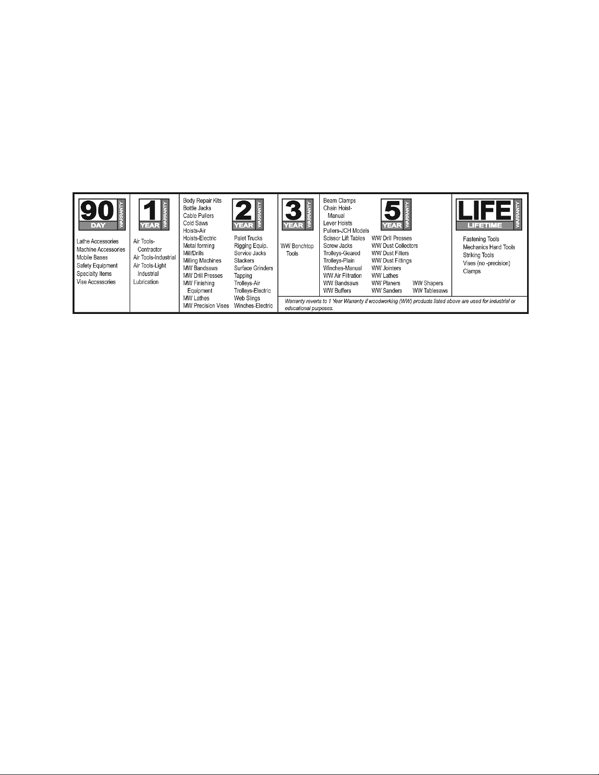
JET products carry a limited warranty which varies in duratio n based upon the product (MW = Metalworking, WW =
Woodworking).
WHAT IS COVERED?
This warranty covers any defects in workmanship or materials subject to the e xceptions stated below. Cutting tools,
abrasives and other consumables are excluded from warranty coverage.
WHO IS COVERED?
This warranty covers only the initial purchaser of the product.
WHAT IS THE PERIOD OF COVERAGE?
The general JET warranty lasts for the time period specified in the product literature of each product.
WHAT IS NOT COVERED?
Five Year Warranties do not cover woodworking (WW) products used for commercial, industrial or educational
purposes. Woodworking products with Five Year Warranties that are used for commercial, industrial or education
purposes revert to a One Year Warranty. T his warranty does not cover defects due directly or indirectly to misuse,
abuse, negligence or accidents, normal wear-and-tear, improper repair or alterations, or lack of maintenance.
HOW TO GET SERVICE
The product or part must be returned for examination, postage prepaid, to a location designated by us. For the name
of the location nearest you, please call 1-800-274-6848.
You must provide proof of initial purchase date and an explanation of the complaint must accompany the
merchandise. If our inspection discloses a defect, we will repair or replace the product, or refund the purchase price,
at our option. We will return the repaired product or replacement at our expense unless it is determined by us that
there is no defect, or that the defect resulted from causes not within the scope of our warranty in which case we will,
at your direction, dispose of or return the product. In the event you choose to have the product returned, you will be
responsible for the shipping and handling costs of the return.
HOW STATE LAW APPLIES
This warranty gives you specific legal rights; you may also have other rights which vary from state to state.
LIMITATIONS ON THIS WARRANTY
WALTER MEIER (MANUFACTURING) INC., LIMITS ALL IMPLIED WARRANTIES TO THE PERIOD OF THE
LIMITED WARRANTY FOR EACH PRODUCT. EXCEPT AS STATED HEREIN, ANY IMPLIED WARRANTIES OR
MERCHANTABILITY AND FITNESS ARE EXCLUDED. SOME ST ATES DO NOT ALLOW LIMITATIONS ON HOW
LONG THE IMPLIED WARRANTY LASTS, SO THE ABOVE LIMITATION MAY NOT APPLY TO YOU.
WALTER MEIER SHALL IN NO EVENT BE LIABLE FOR DEATH, INJURIES TO PERSONS OR PROPERTY, OR
FOR INCIDENTAL, CONTINGENT, SPECIAL, OR CONSEQUENT IAL DAMAGES ARISING FROM THE USE OF
OUR PRODUCTS. SOME STATES DO NOT ALLOW THE EXCLUSION OR LIMITATION OF INCIDENTAL OR
CONSEQUENTIAL DAMAGES, SO THE ABOVE LIMITATION OR EXCLUSION MAY NOT APPLY TO YOU.
Walter Meier sells through distributors only. The specifications in Walter Meier catalogs are given as general
information and are not binding. Members of Walter Meier reserve the right to effect at any time, without prior notice,
those alterations to parts, fittings, and accessory equipment which they may deem necessary for any reason
whatsoever. JET® branded products are not sold in Canada by Walter Meier.
2
Page 3

2.0 Table of contents
Section Page
1.0 Warranty and Service ................................................................................................................... 2
2.0 Table of contents.......................................................................................................................... 3
3.0 Safety warnings ........................................................................................................................... 4
4.0 About this manual ........................................................................................................................ 5
5.0 Specifications............................................................................................................................... 6
6.0 Setup and assembly ..................................................................................................................... 7
6.1 Tool s required .................................................................................................................................................... 7
6.2 Shipping contents .............................................................................................................................................. 7
6.3 Front rail installation .................................................................................................. ........................................ 7
6.4 Switch installation ...................................................................................................... ........................................ 8
6.5 Back rail installation ........................................................................................................................................... 8
6.6 Guide tube .......................................................................................................................................................... 8
6.7 XACTA Fence .................................................................................................................................................... 9
6.8 Leveling fence to saw table............................................................................................................................... 9
6.9 Adjusting fence parallel to miter slot ................................................................................... ............................. 9
6.10 Clamping Pressure ........................................................................................................................................ 10
6.11 Checking 90° to Table ................................................................................................................................... 10
6.12 Cursor Adjustment ......................................................................................................................................... 10
7.0 Replaceme nt Parts ..................................................................................................................... 11
7.1.1 XACTA Fence Rail Assembly – Exploded View .............................................................................. .......... 11
7.1.2 XACTA Fence Rail Assembly – Parts List .................................................................................................. 11
7.2.1 XACTA Fence Assembly – Exploded View ................................................................................................ 12
7.2.2 XACTA Fence Assembly – Parts List ......................................................................................................... 12
3
Page 4

3.0 Safety warnings
1. Read and understand the entire owner's
manual before attempting assembly or
operation.
2. Read and understand warni ngs posted on the
machine and in this manual. Failure to comply
with all of these warnings may cause serious
injury.
3. Replace warning labels if they become
obscured or rem oved.
4. The table saw on which this fence is used, is
designed and intended for use by properly
trained and experienced personnel only. If you
are not familiar with the proper and safe
operation of a table saw, do not use until
proper training and knowledge have been
obtained.
5. Do not use the table saw for other than its
intended use. If used for other purposes,
Walter Meier (Manufacturing) Inc., disclaims
any real or implied warranty and holds itself
harm les s from any injur y that may res ult fro m
that use.
6. Always wear approved safety glasses/face
shields while using the table saw. Everyday
eyeglasses only have impact resistant lenses;
they a re not safety glasses.
7. Before operating the table saw, remove tie,
rings, watches and other jewelry, and roll
sleeves up past the elbows. Remove all loose
clothing and confine long hair. Non-slip
footwear or anti-skid floor strips are
recommended. Do n o t w ear gloves.
8. Always use the blade guard on all ''throughsawing'' operations. A through-sawing
operation is one in which the blade cuts
completely throu gh the workpi ece.
9. Kickback occurs when the workpiece is thrown
towards the operator at a high rate of speed. If
you do not have a clear understanding of
kickback and how it occurs, DO NOT operate
the table sa w!
10. Wear ear protectors (plugs or muffs) during
extended periods o f operation.
11. Some dust created by power sanding, sawing,
grinding, drilling and other construction
activities contain chemicals known to cause
cancer, birth defects or other reproductive
harm. Some examples of these chemicals are:
•
Lead fr om lead based pain t.
Crystalline silica from bricks, cement and
•
other m asonry products.
•
Arsenic and chromium from chemically
tr eated lu m ber.
Your risk of exposure varies, depending on
how often you do this type of work. To reduce
your exposure to these chemicals, work in a
well-ventilated area and work with approved
safety equipment, such as f ace or dust masks
that are specifically designed to filter out
microscopic particles.
12. Do not operate this machine while tired or
under the influence of drugs, alcohol or any
medication.
13. Make certain switch is in OFF position before
connecting the machin e to the power supply.
14. Make certain the machine is properly
grounded.
15 . Make all m ac hine ad just m e nt s o r m ain t e nance
with the machine unplugged from the power
source.
16. Remove adjusting keys and wrenches. Form a
habit of checking to see that keys and
adjusting wrenches are removed from the
machine before turning i t on.
17. Keep safety guards in place at all times when
the machine is in use. If removed for
maintenance purposes, use extreme caution
and replace the guards immediately after
completion of maintenance.
18. Check damaged parts. Before further use of
the machine, a guard or other part that is
damaged should be carefully checked to
determine that it will operate properly and
perform its intended function. Check for
alignment of moving par ts, binding of moving
parts, breakage of parts, mounting and any
othe r co nditio ns th at may aff ect i ts ope ration.
A guard or other part that is damaged should
be properly repaired or replaced.
19. Provide for adequate space surrounding work
area and non- g lare , over he ad lig hting .
20. Keep the floor around the machine clean and
free o f scr ap material, oil a nd grease.
21. Keep visitors a safe distance from the work
area . Keep children away.
22. Make your workshop child proof with padlocks,
master swi tches or by rem oving starter keys.
23. Give your work undivided attention. Looking
aroun d, ca rrying on a conver sation an d “horseplay” are careless acts that can result in
seri ous inj ury.
4
Page 5

24. Maint ain a balanced stance at all times so that
you do not fall into the blade or other moving
parts. Do not overreach or use excessive force
to per form any machine operation.
25. Use the right tool at the correct speed and
fee d rate. D o not forc e a tool or attachme nt to
do a job for which it was not designed. The
ri ght tool will do th e job better and more safel y.
26. Use recommended accessories; improper
accessories m ay be hazardous.
27. Maintain tools with care. Keep saw blades
sharp and clean for the best and safest
pe rform ance . F o llow instruc tions f o r lubric ating
and changing a ccessories.
28. Turn off the machine before cleaning. Use a
brush or compressed air to remove chips or
debri s — do not use your ha nds.
29. Do not stand on the machine. Serious injury
could occur if the machine tips over.
30. Never leave the machine running unattended.
Turn the power off and do not leave the
machine until it comes to a com plete stop.
31. Remove loose items and unnecessary work
pieces from the area before starting the
machine.
32. Keep hands out of the line of saw blade.
33. Use a push-stick w hen requi red.
34. Pay particular attention to instructions on
reducing risk of kickba ck.
35. Do not perform any operation freehand.
36. Never rea ch arou nd or over sa w blade.
37. Don’t use in dangerous environment. Don’t
use power tools in damp or wet location, or
expose them to rain. Keep work area well
lighted.
4.0 About t hi s manual
This manual is provided by Walter Meier (Manufacturing) Inc. covering the assembly and adjustment
procedu res for a JET X ACTA
on installation, safety precautions, and parts breakdown. Your fence has been designed and constructed to
provide years of trou ble-free operation if used in accordan ce with the instruction s as set forth in this document.
If there are questions or comments, please contact your local supplier or W alter Meier. W alter Meier can also
be reached at our web site: ww w.walt ermei er.com .
Retain this manual for future reference. If the fence transfers ownership, the manual should accompany it.
Read and understand the entire contents of the table saw manual before attempting
operat ion of the rip fence. Failure to compl y m ay cause serious injur y.
®
Fence syste m for the JTAS-12-D X Table Saw. This ma nual cont ains instru ction s
5
Page 6

5.0 Specifications
XACTA Fence :
Stock number...................................................................................................................................................... 708955Z
Fence body length ............................................................................................................................... 40-1/2” (1029 mm)
Side plate length ........................................................................................................................................ 42” (1067 mm)
Side plate thickness .................................................................................................................................. 19/32” (15 mm)
Side plate material ........................................................................................................................................ polyethylene
Fence width ............................................................................................................................................. 4-1/4” (108 mm)
Fence height .............................................................................................................................................. 2-1/2” (64 mm)
Head length ................................................................................................................................................. 16” (406 mm)
Net weight (fence only) ...............................................................................................................................23 lb (10.4 kg)
Paint finish ..................................................................................................................................................... powder coat
Rail Assembly:
Stock number ....................................................................................................................................................708956Z
Maximum rip to right of blade .................................................................................................................50” (1270 mm)
Maximum rip to left of blade ..................................................................................................................... 14” (356 mm)
Guide tube dimensions ............................................................................ 84-3/8”L x 3”W x 2”H (2143 x 76 x 51 mm)
Front rail dimensions.......................................................................... 72”L x 2-1/2”W x 2-1/2”H (1830 x 64 x 64 mm)
Rear rail dimensions ............................................................................ 72” x 1-1/2”W x 1-1/2”H (1830 x 38 x 38 mm)
Paint finish ..................................................................................................................................................... powder coat
The specifications in this manual were current at time of publication, but because of our policy of continuous
improvement, Walter M eier (Manufacturing) Inc., reserves the ri ght to change speci fications at any time and wi thout
prior notice, without incurring obligations.
6
Page 7

6.0 Setup and assembly
Open shipping cartons and check that all parts are
intact. Report any damage immediately to your
distributor. Read the instruction manual thoroughly
for assembly, alignment, and maintenance
instructions.
6.1 Tools required
1 #3 cross p oin t screwdr iver
1 7/16” wrench
1 1/2" wrench
1 Combinati on square & straight edge
1 1/4” h ex key
1 3/16” hex key
6.2 Shipping contents
1 XACT A Fence II
1 Front rail
1 Back rail
1 Guide tube
3 Black plastic end covers
1 Owner’s manual
1 Warranty registration card
1 Hardware package (p/n XF12DX-H P )*
contains:
7 Flat head screws, 1/4 x 1-1/2 (HP-1)
5 Hex cap screws, 1/4 x 1-1/2 (HP-2)
7 Hex cap screws, 1/4 x 3/4 (HP-3)
2 Hex cap screws, 5/16 x 3/4 (HP-4)
2 Flat washers, 5/16 (HP-5)
24 Flat washers, 1/ 4 (HP-6)
19 Lock washers 1/4 (HP-7)
12 H ex nuts 1/4 (HP-8)
* Hard ware package is shipped inside guide tube.
Contents a re shown full scale in Figure 1.
6.3 Front rail installation
1. Identify the front rail (A, Figure 2), which is
2-1/2" x 2-1/2" with notches on one side and
countersu nk mounting holes on th e other side.
Figur e 1
2. Lightly secure front rail (A) to table with seven
1/4 x 1-1/2 screws, flat washers, lock washers
and he x nuts (HP-1/6/7/8). Tighten just enough
to hold rail next to table but loose enough to
allow height adjustment.
Figur e 2
7
Page 8

The front rail must be low enough to clear the miter
gauge slot, and para llel to the table top:
1. Place an adjustable square on the table as
shown in Figure 3.
2. Check height of front rail at several locations
along the surface of the saw table. The front
rail must be parallel with table top.
3. When front rail has been correctly positioned,
use a screwdriver and 7/16" wrench to tighten
nuts securely. However, do not tighten
hardware for the farthest left hole; it should
remain loose to accommodate switch
installation (below).
Figur e 4
Figur e 5
Figur e 3
6.4 Switch installation
At this time refer to your JTAS-12DX Table Saw
man ual and mount the switc h as d escr ibed in the
Installing Switch section. The switch should be
mounted before the guide tube installation
described later in this manual.
6.5 Back rai l instal latio n
1. Locate the back rail which is 2" x 2" with holes
runn ing along one side on ly. Height of ba ck rail
when atta ched to the saw is not criti cal.
2. Align holes in back rail to holes in table top.
3. Secure back rail to pre-tapped holes in saw
table with two 5/16 screws and flat washers
(HP-4/5), as sh own in Figu re 4. Tighten screws
securely with 1/2" wrench.
4. Secure remainder of back rail with 1/4 screws,
flat washers, lock washers, and hex nuts (H P-
2/6/7/8) as shown in Figure 5.
5. Tighten all nuts.
6.6 Guide tube
Important: Before proceeding with guide tube
instal lation, the table saw switch should already be
installed. If not, refer to the Switch Installation
secti on in your JTAS -12-DX Saw manual.
Referring to Figure 6:
The guide tube (A) is placed on top of front rail (B)
and is mount ed with scale facing towar d operator .
1. Align holes in bottom of guide tube with holes
in front rail. When properly positioned, the
guide tube should extend beyond the front rail
about 6" in both directi ons.
2. Fasten guide tube (A) to front rail (B) from
beneath, with seven 1/4" screws, lock
washers, and flat washers (H P-3/6/7). Fingerti ghten onl y until all scr ews are inserted.
3. Tighten all screws with a 7/16" wrench.
8
Page 9

6.8 L eveling fence to saw t able
Place fence on ta ble and lock it.
1. View the fence from left side of saw (Figure 9).
Look for the space between the table and the
fence bottom to be equal along entire length of
fence (A, B, Figure 9).
Figur e 6
6.7 XACT A Fence
Screw knob into threaded handle on fence, as
shown in Figure 7.
Figur e 7
The lock lever has three functional positions as
shown in Figure 8:
Figur e 9
If adjustment is necessary:
2. Unlock fence.
3. Raise or lower two nylon adjustment screws
(D, Figure 10) the same number of turns until
the space between bottom of fence and table
is the same. Care must be taken to raise or
lower fence on each side equally or the fence
may not be 90° to the table after the height
adjustment i s perfor m ed.
Figur e 10
Figur e 8
1. Upright position permits mounting and removal
of fence from saw .
2. Unlock position permits ea sy fence positioning.
3. Lower position locks f ence to guide tube. The
cam handle should be pushed down firmly
against the pin.
6.9 Adjusting fence parallel to miter
slot
1. Place fence next to outside edge of right miter
slot and lock it.
2. Fence should be ev en with m iter slot from front
to back.
3. If fence is not even along length of miter slot,
unlock fence, remove it and turn it upside
down.
4. Adjust one of two setscrews (A, Figure 11)
unt il fence is even with miter slot edge along
its entire length when locked.
Note: You may need to re-adjust the clamping
pressure after aligning the fence.
9
Page 10

6.12 Cu rsor Adjustment
1. Disconnect sa w from power source.
2. Raise blade above t able top.
3. Unlock fence and slide it to approximately four
inches from blade.
4. Lock the fence.
5. Measure distance between saw blade and
inside of fence.
Figur e 11
6.10 Clampin g P ressure
The XACTA Fence has been adjusted by the
manufacturer to lock securely when lock handle is
pushed down. If adj ustment is needed:
1. Unlock fence.
2. Remove fence from guide tube and turn it
over.
3. Adjust each of two setscrews (A, Figure 11)
exactly the same number of rotations until the
fence is held securely when lock handle is
pushed down.
6.11 Ch ecki ng 90° to T able
1. Place fence on saw ta ble and lock it.
2. Place a square (A, Figure 12) on table next to
fence. The fen ce should be 90° to the table.
3. If adjustment is necessary, unlock fence and
turn one of two nylon adjustment screws (B,
Figure 12) until fence i s 90° to table.
4. Lock fence and check the adjustment again.
6. Adjust cursor (C, Figure 12) to read the
distance just measured, and tighten cursor
assembly to fence.
7. Make a tes t c ut and c onf irm the adjus tme nt is
correct.
Note: If the cursor does not have enough travel to
give the correct measurement, loosen guide rail
and adjust as needed. If you still do not get the
correct measurement, loosen front rail and adjust
as needed. If you have to adjust front rail you will
need to go through the front rail assembly
instructions again.
Cursor accuracy should be checked whenever a
dif ferent blade is installed.
Af ter installing the XA CTA Fence, pre ss the black
plastic end covers into the openings of the guide
rail . There is also an end co ver fo r the fe nce that
may already be inst alled.
Figure 12
10
Page 11

7.0 Repl acement Parts
Replacement parts are listed on the f ollowing pages. To order parts or reach our service department, call 1800-274-6848 Monday through Friday (see our website for business hours, www.jettools.com). Having the
Model Number and Serial Number of your machine available when you call will allo w us to s erve yo u quickly
and accur ate ly.
7.1.1 XACTA Fence Rail Assemb ly – Expl oded V iew
7.1.2 XACTA Fence Rail Assemb ly – Part s List
Index No Part No Description Size Qty
....................708956Z...................... XACTA Rail Assembly 50” (index # 1-13) ................ ........................................ 1
1..................XF12DX-201............... Front Rail ..................................................................... ........................................ 1
2..................TS-081F081 ............... Flat Head Screw ......................................................... 1/4”-20 × 1-1/2”.............. 7
3..................TS-0680021................ Flat Washer ................................................................. 1/4” ............................... 24
4..................TS-0720071................ Lock Washer ............................................................... 1/4” ............................... 19
5..................TS-0561011................ Hex Nut ....................................................................... 1/4”-20 .......................... 12
6..................TS-0050031................ Hex Cap Screw ........................................................... 1/4”-20 × 3/4” ................. 7
7..................XF2-207 ...................... Scale............................................................................ 50” .................................. 1
8..................XF2-208 ...................... Guide Rail ................................................................... 50” .................................. 1
9..................XF12DX-209............... Rear Rail ..................................................................... 50” .................................. 1
10................XF2-210 ...................... Guide Cover ................................................................ ........................................ 2
11................TS-0081031................ Hex Cap Screw ........................................................... 5/16”-18 × 3/4” ............... 2
12................TS-0050071................ Hex Cap Screw ........................................................... 1/4”-20 × 1-1/2”.............. 5
13................TS-0680031................ Flat Washer ................................................................. 5/16” ............................... 2
....................XF12DX-HP................ Hardware Package (index # 2-6 and 11-13) ............ ...........................................
11
Page 12
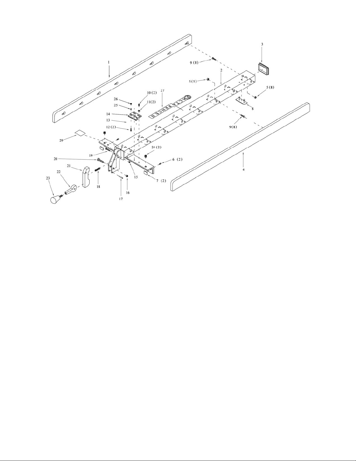
7.2.1 XACTA Fence Assembly – Exploded View
7.2.2 XACTA Fence Assemb l y – P art s List
Index No Part No Description Size Qty
....................708955Z...................... XACTA Commercial Fence 40” (index # 1-29)......... ........................................ 1
1..................XF12DX-101............... Left Side Plate ............................................................ ........................................ 1
2..................XF12DX-102............... Fence Body Assembly ............................................... ........................................ 1
3..................XF2-103 ...................... Tube Cover ................................................................. ........................................ 1
4..................XF12DX-104............... Right Side Plate .......................................................... ........................................ 1
5..................TS-0640071................ Lock Nut ...................................................................... 1/4” × 20....................... 16
6..................TS-0271031................ Socket Set Screw ....................................................... 3/8”-16 × 3/8” ................. 2
7..................3575081 ...................... Fluoroway Pad ............................................................ ........................................ 2
8..................XF-8A .......................... Pad .............................................................................. ........................................ 1
9..................TS-0151011................ Carriage Bolt ............................................................... 1/4”-20 × 3/4” ............... 16
10................TS-081D022 ............... Pan Head Machine Screw ......................................... 10-32 × 3/8” ................... 2
11................TS-0680021................ Flat Washer ................................................................. 1/4” ................................. 2
12................TS-081D021 ............... Flat Head Machine Screw.......................................... 10-32 × 3/8” ................... 2
13................800708950D ............... Cursor .......................................................................... ........................................ 1
14................800708950C ............... Cursor Bracket ............................................................ ........................................ 1
15................TS-0640071................ Lock Nut ...................................................................... 1/4” × 20......................... 1
16................TS-0640081................ Lock Nut ...................................................................... 5/16”-18.......................... 1
17................XF2-117 ...................... Spring Pin.................................................................... 4 × 28mm ....................... 1
18................6813042 ...................... Compression Spring ................................................... ........................................ 1
19................TS-0151041................ Carriage Bolt ............................................................... 1/4”-20×1-1/2”................ 1
20................TS-0152031................ Carriage Bolt ............................................................... 5/16”-18 × 1-1/2” ........... 1
21................3215301 ...................... Foot Cam..................................................................... ........................................ 1
22................3076232 ...................... Lock Cam .................................................................... ........................................ 1
23................6430055 ...................... Knob w/stud ................................................................ ........................................ 1
24................XF-5 ............................ Nylon Adjustment Screw ............................................ 1/2” × W12 ..................... 2
25................TS-0680021................ Flat Washer ................................................................. 1/4” ................................. 2
26................TS-0560081................ H ex Nut ....................................................................... 10-32 .............................. 2
27................XF-27 .......................... XACTA Fence II Label ............................................... ........................................ 1
29................XF-29 .......................... JET Label .................................................................... ........................................ 1
12
 Loading...