

Page 1

This Manual is Bookmarked
Operating Instructions and Parts Manual
Heavy-Duty Mortiser
Model 720HD
WMH TOOL GROUP
2420 Vantage Drive
Elgin, Illinois 60123 Part No. M-1791309
Ph.: 800-274-6848 Revision A 7/05
www.wmhtoolgroup.com Copyright © WMH Tool Group
Page 2

This manual has been prepared f or the owner and operators of a P owermatic Model 720HD Morti ser. It s
purpose, aside f rom machine oper ation, is to promot e safety using acc epted operati ng and maint enance
procedures. To obtai n m axim um life and eff ici ency from your mortiser and t o aid i n usi ng it saf ely, please
read this manual thoroughly and follow the instructions carefully.
Warranty and Service
WMH Tool Gr oup warrants ever y product it sell s. If one of our tools needs s ervice or repai r, one of our
Authorized Repair St ations located throughout the United St ates can provide quick service or information.
In most cases, a WM H Tool Group Repair Station can as si st in authorizi ng r epair work, obtaini ng par ts, or
perform routi ne or m ajor maintenance repair on your Powermatic product.
For the nam e of an A uthoriz ed Repair St ation in your area, pl ease call 1-800-274-6848, or v isit our web
site at www.wmhtoolgroup.com
More Information
Remember, WMH Tool Group i s consistently adding new products to the li ne. For complete, up-to-dat e
product information, check with your local WMH Tool Group distributor, or visit our web site at
www.wmhtoolgroup.com
WMH Tool Group Warranty
WMH Tool Group makes every effort to assure that its produc ts meet high qualit y and durability standards
and warrants to the original retail consumer/purchaser of our products that each product be free from
defects in mat erials and workmanship as foll ows: 1 YEA R LIMITED WARRANTY ON ALL PRODUCTS
UNLESS SPECIFIED OTHERWISE. This Warranty does not apply to defects due directly or i ndirectly to
misuse, abuse, negl igence or acc idents, norm al wear-and-tear , repair or alterati ons outside our f aciliti es,
or to a lack of maintenanc e.
WMH TOOL GROUP LIMITS ALL IMPLIED WARRANTIES TO THE PERIOD SPECIFIED ABOVE,
BEGINNING FROM THE DATE THE PRODUCT WAS PURCHASED AT RETAIL. EXCEPT AS STATED
HEREIN, ANY IMPLIED WARRANTIES OR MERCHANTABILITY AND FITNESS ARE EXCLUDED.
SOME STATES DO NOT ALLOW LIMITATIONS ON HOW LONG THE IMPLIED WARRANTY LASTS,
SO THE ABOVE LIMITATION MAY NOT APPLY TO YOU. IN NO EVENT SHALL WMH TOOL GROUP
BE LIABLE FOR DEATH, INJURIES TO PERSONS OR PROPERTY, OR FOR INCIDENTAL,
CONTINGENT, SPECIAL, OR CONSEQUENTIAL DAMAGES ARISING FROM THE USE OF OUR
PRODUCTS. SOME STATES DO NOT ALLOW THE EXCLUSION OR LIMITATION OF INCIDENTAL
OR CONSEQUENTIAL DAMAGES, SO THE ABOVE LIMITATION OR EXCLUSION MAY NOT APPLY
TO YOU.
To take advantage of this warranty, the product or part must be returned for examination, postage
prepaid, to an Authorized Repair Station designated by our office. Proof of purchase date and an
explanati on of the complaint m ust accompany the merchandi se. If our inspecti on discloses a defec t, we
will either repair or replace the product at our discret i on, or refund t he purchase pri ce if we cannot readi l y
and quickly provide a repai r or replac ement. We will return the repai red product or replacem ent at WMH
Tool Group’s ex pense, but if it is determ ined there i s no defect, or that the def ect resulted f rom causes
not within the scope of WMH Tool Group’s warranty, then the user must bear the cost of storing and
returning t he product . This warranty gives you specifi c legal right s; you m ay also have ot her right s, which
vary from state t o state.
WMH Tool Group sells through distribut ors only. Members of the WMH Tool Group reserve the right to
effect at any time, wit hout prior notice, alter ations to parts, fittings and accessory equi pment, which they
may deem necessary for any reason whatsoever.
2
Page 3

Table of Contents
Warranty and Servic e ..............................................................................................................................2
Table of Contents....................................................................................................................................3
Warning...................................................................................................................................................4
Introduction..............................................................................................................................................6
Specifications..........................................................................................................................................6
Unpacking ...............................................................................................................................................7
Contents of the Shipping Container......................................................................................................7
Assembly.................................................................................................................................................8
Installing Handle...................................................................................................................................8
Installing Wood Table...........................................................................................................................8
Installing B ushing, Chisel and Auger.....................................................................................................9
Grounding Instructions............................................................................................................................. 9
Extension cords.................................................................................................................................. 10
Adjustments...........................................................................................................................................11
Squaring Table To Chisel...................................................................................................................11
Setting Table to Vertical Position........................................................................................................11
Table Removal and Stor age............................................................................................................... 11
Chuck Extension A daptor...................................................................................................................12
Depth Setting Rod ..............................................................................................................................12
Head Movement.................................................................................................................................12
Clamp.......................................................................................................................... ......................13
Stock Stop..........................................................................................................................................13
Setting Lateral Stops ..........................................................................................................................13
Chisel Parallel to Workpiece...............................................................................................................14
Lower Work Support...........................................................................................................................14
Re-setting the Head...........................................................................................................................14
Gib Adjustment................................................................................................................................... 14
Tool Stora g e......................................................................................................................................15
Operating Controls.................................................................................................................................15
Operation...............................................................................................................................................16
Sharpening Chisel and Auger.............................................................................................................17
Lubrication .........................................................................................................................................17
Replacement Parts................................................................................................................................18
720HD Heavy Duty Mortiser...............................................................................................................19
Parts List: 720HD Heavy Duty Mortiser...............................................................................................20
Electrical Connections ...........................................................................................................................23
3
Page 4

Warning
1. Read and understand the entire owners manual befor e attempting assembly or operation.
2. Read and understand the warnings po sted on the m achine and i n thi s manual. Failur e to comply wit h
all of these warnings m ay cause seriou s i njury.
3. Replace the warning labels if they become obscured or removed.
4. This mortiser is designed and i ntended f or use by properly trained and ex perienced per sonnel onl y. If
you are not f amiliar wit h the proper and safe operat ion of a mortiser, do not use unti l proper training
and knowledge have been obtained.
5. Do not use this mor tiser f or other t han i ts i ntended use. If used f or other purposes, W MH T ool Group
disclaim s any real or i mplied warrant y and h olds itsel f harml ess from any injury t hat may r esult f rom
that use.
6. Always wear approved safety glasses/face shields while using this mortiser. Everyday eyeglasses
only have impact resi stant lenses; they are not safet y glasses.
7. Before operating this morti ser, remove tie, ri ngs, watches and other jewelry , and roll sl eeves up past
the elbows. Rem ove all l oose clothing and confine long hair . Non-slip footwear or anti-skid floor strips
are recommended. Do not wear gloves.
8. Wear ear protector s (plugs or muffs) during extended peri ods of oper ation.
9. Some dust created by power sanding, sawing, grinding, drilling and other construction activities
contain chemi cals known to cause cancer , bir th defects or other r eproductiv e harm . Some examples
of these chemic als are:
• Lead from lead based paint.
• Crystalli ne sil ic a from bricks, cement and other masonry pr oduc ts.
• Arsenic and chromium from chemically treated lumber .
Your risk of exposure varies, depending on how often you do this type of work. To reduce your
exposure to these chemicals, work in a well-ventilated area and work with approved safety
equipment, such as face or dust masks that are specifically designed to filter out microscopic
particles.
10. Do not oper ate this machine while tir ed or under the influence of drugs, alcohol or any m edic ation.
11. Make certain the machine is proper ly grounded.
12. Make all machine adjustm ents or maintenance with the machine unplugged f rom the power source.
13. Remove adjusting keys and wrenches. Form a habit of checking to see that keys and adjusting
wrenches are removed from the machine before turning it on.
14. Keep safety guards in place at all times when the machine is in use. If removed for maintenance
purposes, use extreme caution and replace the guards immediately.
15. Check damaged parts. Before further use of the machine, a guard or other part that is damaged
should be carefully checked to determine that it will operate properly and perform its intended
function. Check for alignment of moving part s, binding of moving parts, br eakage of parts, mounting
and any other condi ti ons that m ay affect its operati on. A guard or ot her part that i s damaged shoul d
be properly repaired or replaced.
16. Pr ovide for adequate space surrounding work area and non-glar e, overhead lighting.
17. Keep the floor around the machi ne cl ean and free of scrap material, oil and grease.
18. Keep v isitors a safe distance from the work area. Keep children away.
19. Make your workshop child proof wi th padlocks, master switches or by remov ing starter keys.
20. Giv e your work undivi ded attention. Looking ar ound, carryi ng on a conversation and “ horse-play” ar e
careless acts that can r esul t in serious injury.
4
Page 5

21. Mai ntain a bal anced stance at al l tim es so that y ou do not f all or l ean agai nst the auger and chi sel or
other movi ng parts. Do not overreach or use excessiv e force to perform any machine operation.
22. Use the ri ght t ool at the corr ect speed and f eed rat e. Do not forc e a tool or att achment to do a job for
which it was not designed. T he ri ght tool will do the job better and safer.
23. Use recom mended accessories; improper accessories m ay be hazardous.
24. Maintain tools with care. Keep augers and chisels sharp and clean for the best and safest
performance. Follow instructions for lubricating and changing accessories.
25. Make sure t he work piece is securely clam ped against table and/or f ence. Never use your hand t o
hold the work piec e.
26. Do not turn on the power while the auger or chisel is cont ac ting a workpiece.
27. T urn off the machine before cleaning. Use a brush or compressed air to remov e c hips or debris — do
not use your hands.
28. Do not stand on the machine. Serious injur y c ould oc cur if the machine tips over.
29. Never leave t he machine runni ng unattended. Turn the power of f and do not leav e the mor tiser until
the auger comes to a complete stop.
30. Remove loose items and unnecessary work pieces from the area befor e start ing the machine.
Familiarize you rself with the following safety no tices used in this manual:
This means that if precautions are not heeded, it may result in minor injury and/or
possible machine damage.
This means that if precautions are not heeded, it may result in serious injury or possibly
even death.
- - SAVE THESE INSTRUCTIONS - -
5
Page 6

Introduction
This manual is provided by W MH Tool Group cov ering the safe oper ation and mai ntenance procedure s
for a Model 720HD Heavy-Duty Mortiser. This manual contains instructions on installation, safety
precautions, gener al oper ati ng procedur es, mai ntenance i nstructi ons and parts breakdo wn. Thi s mac hine
has been designed and con structed t o provide year s of troubl e free operation if used in accordance wi th
instructi ons set forth i n this manual . If there are any questions or comm ents, please contact either your
local supplier or WMH Tool Group. WMH Tool Group can also be reached at our web site:
www.wmhtoolgroup.com.
Specifications
Model Number................................................................................................................................720HD
Stock Number.............................................................................................................................. 1791309
Chuck Capacity (in.)..............................................................................................................................1/2
Spindle Taper...................................................................................................................................JT33
Bushing Inside Diameter (in.)..........................................................................................3/4, 5/8 and 1-1/8
Chisel Stroke (in.)..............................................................................................................................6-1/8
Maximum Chisel Travel (in.):
Side to Side....................................................................................................................................9-1/8
Front to Back..................................................................................................................................3-3/8
Table Size (L x W)(in.).........................................................................................................14-5/8 x 7-1/ 8
Maximum Workpi ec e Height – wit hout Table (in.)...................................................................................46
Maximum Workpiece Height – with Table (in.)..................................................................................11-1/2
Clamp Surface (L x W)(in.)...........................................................................................................8 x 2-3/4
Table Tilt (deg.) ..................................................................................................................90 left, 45 right
Fence Size (L x W)(in.)...................................................................................................... 20-1/2 x 11-3/4
Base Size (L x W)(in.)........................................................................................................ 25-1/2 x 21-1/2
Overall Height (in.).................................................................................................................................80
Motor........................................................................................................... TEFC, 1.5HP, 1Ph, 230V only
Motor Speed (RPM)..........................................................................................................................1,720
Approximate Shipping Weight (lbs.).....................................................................................................575
Approximate Net Weight (lbs.) .............................................................................................................490
The above specifications were current at the time this manual was publi shed, but because of our policy of
continuous im provement, WMH Tool Group reserv es the right to change specif ications at any tim e and
without pri or notic e, without incurring obligations.
6
Page 7
Unpacking
Remove all c rating and pl astic from ar ound the
Mortiser. Check f or shipping dam age; report any
damage immediately to your distributor and
shipping agent. Do not discard any shipping
material until the Mortiser is assembled and
running properly.
Open the cabinet rear door and remove any
boxes and accessory items. Compar e these with
the following part s list to mak e sure all parts are
intact. Mi ssing parts, if any, should be reported
to your distributor. Read the instruction manual
thoroughly for assembly, maintenance and
safety instructions.
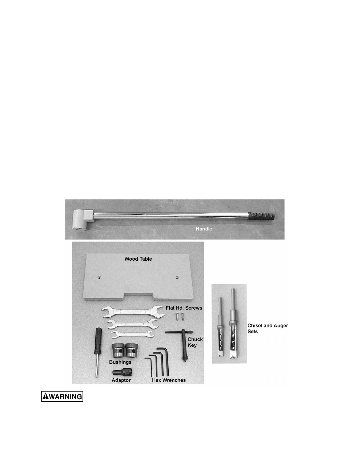
Contents of the Shipp ing Container
1 Mortiser
1 Handle
1 Chisel and Auger set – 3/ 4”
1 Chisel and Auger set - 1”
3 Bushings - 5/8”, 3/ 4” and 1- 1/8” I.D.
(NOTE: The 5/8” bushing i s al r eady installed
on the mortiser)
3 Combinati on Wr enc hes: 12- 14, 17-19, 22-24
4 Hex (Allen) Wrenc hes: 3, 4, 5 and 6mm
1 Chuck Key
1 Chuck Extension A daptor
1 Wood Table
2 Phillips Flat Head Scr ews, M6 x 20L
1 Reversibl e (Cross Point/Flat Head)
Screwdriver
1 Owner's Manual
1 Warranty Card
Read and understand the entire contents of this manual before attempting set-up
or operation! Failure t o co mpl y may cause seri ou s injury.
7
Page 8
Assembly
Tools required for assembly
forklift or hoist with straps/slings
14mm wrench (provided)
4 and 6mm hex wrenches (provided)
1. Remove the four screws that secure the
Mortiser to the wood pallet, using a 14mm
wrench.
2. With a forklift or hoist, lift the machine off the
pallet and into its desired location.
3. The Mortiser should be located in a dry
area, on a sturdy, level floor, and with
sufficient lighting. Leave plenty of space
around the machine for operations and
routine maintenance work.
4. If desired, the Mortiser can be further
stabilized by securing it to the floor, using
lag screws through the four holes in the
base.
The mortiser should be
disconnected f rom the power source during
assembly procedures.
5. Unpai nted areas of the machine have been
treated with a r ust prev entative. This should
be removed with a soft cloth and a mild
solvent. Do not use paint thinner, lacquer
thinner, gasoline or miner al spirits; these will
damage paint ed surfaces and pl astic par ts.
Do not use an abrasive pad.
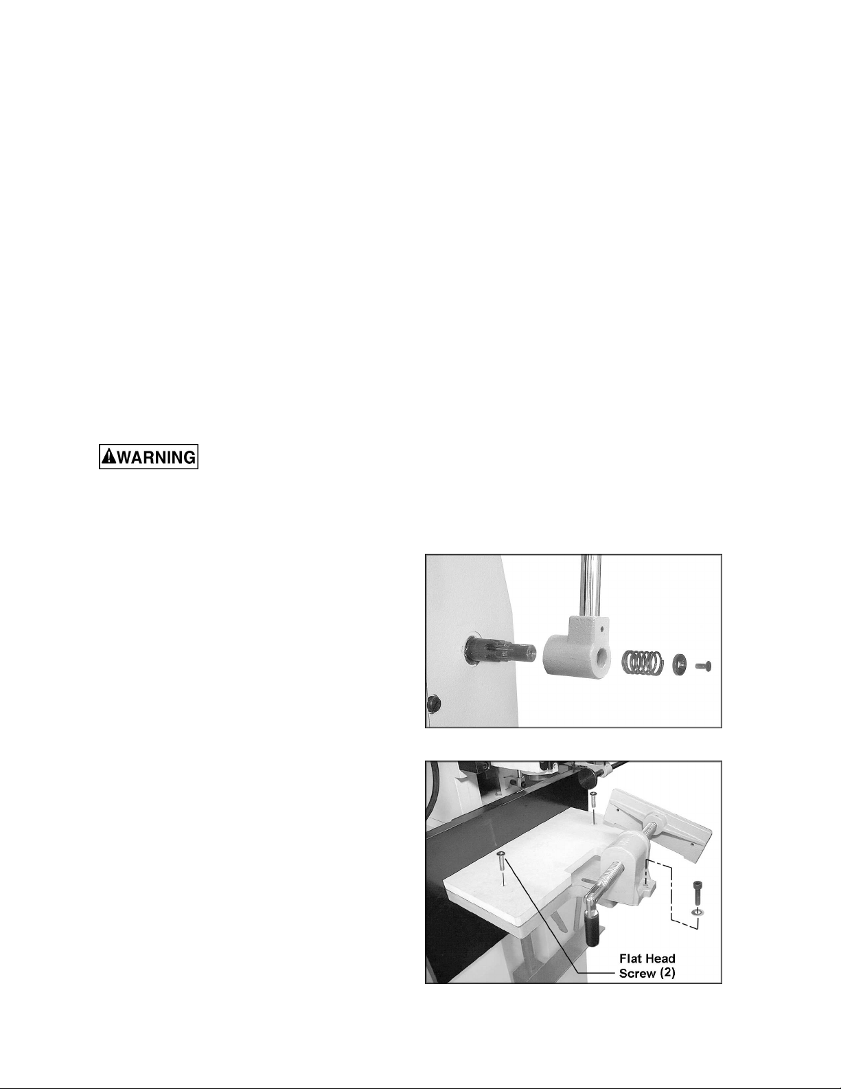
Installing Handle
1. Use a 4mm hex wrench to remove the
screw, washer and spring from the shaft
(Figure 1).
2. Mount the hub of the handl e onto the shaf t
as shown. Make sure the hub slides all the
way onto the shaft.
3. Re-install spring, washer and screw. T ighten
screw.
Installing Wood Table
1. To install the wood table, first remove the
right hand screw at the right of the clamp
(Figure 2), with a 6mm hex wrench, and
loosen the left hand screw from beneath.
Pivot the clam p out of the way.
2. Mount the wood table with two flat head
screws as shown.
3. Re-position t he clamp and install the screw.
Figure 1
Figure 2
8
Page 9

Installing Bushing, Chisel and Auger
4
1. The mortiser should be disconnected from
power source.
2. Open the chuck access cover ( A, Figure 3).
3. Insert a bu shing (B, Fi gure 3) into the hole
with the bushing’s hole facing the front
toward the set screw (C, Figur e 3) .
NOTE: The Morti ser i s shipped with t he 5/8”
bushing pre-installed.)
4. Tighten the set screw (C, Figure 3) with a
mm hex wrench just enough to hold
bushing in plac e.
5. Place the chisel (D, Figure 3) and auger ( E,
Figure 3) beneat h the bushi ng and all ow the
auger to rest upon the table while pushing
the chisel up through the bushing.
6. The cutti ng portion of the auger m ust clear
the chisel by about 1/16” to 3/16”,
depending upon the type of wood to be
worked. Place a “spacer” of 1/8” to 3/16”
diameter (a hex wrench works well)
between bushing and chisel, and push
chisel up until it contacts the spacer.
7. Tight en the set screw (C, Figure 3) t o hold
the chisel in plac e, and rem ov e spacer.
8. Push the auger up through the chisel
opening and into t he chuck as far as it wil l
go. Tight en the auger i n the chuc k using t he
chuck key.
9. Loosen the set screw (C, Figure 3) and
push the chisel all the way up until it
contacts the bushing. This should provide
the proper distance so that the cutting
portion of the auger clears the chisel.
Tighten the set screw (C, Fi gur e 3) .
NOTE: Set the slot in the side of the chisel
to the left or right, if the cut is to be done
laterall y; and fr ont or back if the cut is to be
done front to back. The chisel slot should
always be positioned so chips are being
released into the already-cut part of the
workpiece.
10. Close the c huck access cover (A, Figure 3)
before operating.
Figure 3
Grounding Instructions
Electrical connections must
be made by a qualified electrician in
compliance with all relevant codes. This
machine must be properly grounded to help
prevent electrical shock and possible fatal
injury.
9
Page 10

This mac hine m ust be grounded. I n the event of
a malfuncti on or break down, groundi ng prov i des
a path of least resi stance f or electri c current to
reduce the ri sk of el ectri c shock.
Improper connection of the equipmentgrounding conductor can result in a risk of
electric shock. The conductor, with insulation
having an outer surface that is green with or
without yellow stripes, is the equipmentgrounding conductor. If r epair or replac em ent of
the electric cord or plug is necessary, do not
connect the equi pment-grounding conduc tor to a
live terminal.
Check with a qualified electrician or service
personnel if the grounding instructions are not
completely understood, or if in doubt as to
whether the tool i s properly grounded. Us e only
three wire extensi on c or ds that have three-prong
grounding plugs and three- pole recept acles that
accept the tool’s plug.
The Mortiser is factory wired for 230 volt. You
may either install a plug or “hard-wire” the
machine directly to a control panel.
If you are connecting a plug, use a proper
UL/CSA listed grounding plug suitable for 230
volt operation, similar to that shown in Figure 4.
The Morti ser with a 230 volt plug should onl y be
connected to an outlet having the same
configurati on. No adapter is av ailable or should
be used with the 230 volt pl ug.
If the Mortiser is to be hard-wired to a panel,
make sure a disconnect is available for the
operator. During hard-wiring of the Mortiser,
make sure the fuses hav e been removed or the
breakers have been tripped in the circuit to
which the Mortiser will be connected. Place a
warning placard on the fuse holder or circuit
breaker to prevent it being turned on while the
machine is being wired.
Make sure the voltage of your power supply
matches the specif ications on the m otor plate of
the Mortiser.
Figure 4
Recommended Gauges (AWG) of Extension Cords
Extension Cord Length *
25
50
75
100
150
Amps
feet
feet
feet
feet
feet
200
feet
Extens ion cords
If an extension cord is necessary, make sure the
cord rating i s suitable for the am perage listed on
the machine’s motor plate. An undersized cord
will cause a drop in line voltage resulting in loss
< 5 16 16 16 14 12 12
5 to 8 16 16 14 12 10 NR
8 to 12 14 14 12 10 NR NR
12 to 15 12 12 10 10 NR NR
of power and overheating.
Use the chart in Fi gure 5 as a general guide in
choosing the cor rect size cord. If in doubt, use
15 to 20 10 10 10 NR NR NR
21 to 30 10 NR NR NR NR NR
the next heavi er gauge. The smaller the gauge
number, the heavier the cord.
*based on li miting the l in e vol tage drop t o 5V at 150% of the
rated amp eres.
NR: Not Recommended.
Figure 5
10
Page 11

Adjustments
Squaring Table To Chisel
1. Place a sq uare upon the table and against
the chisel, as shown in Figur e 6.
2. If the table and c hisel are not perpendic ular
to each other, loosen the table’s stud with
the attached hex wrench ( A , Fi gur e 6) .
3. Loosen the l ocking handle (B, Figur e 6) and
adjust the tabl e until the table and chi sel are
square.
4. Re-tighten the stud (A, Figure 6) and locking
handle (B, Figure 6) .
5. Make sure the pointer aligns with zero on
the scale. Loosening the screw on the
pointer will allow slight adjustment of the
pointer if necessary.
NOTE: The l ocking handle (B, Figure 6) can be
rotated out of the way. Simply lift up on the
handle, rotate it on the pin, then release the
handle, making sure it seats itself properly on
the pin.
Setting Table to Vertical Position
For table angl es fr om 45° to 90°:
1. Loosen the stud (A, Figure 7).
2. Unscrew and rem ov e the locki ng handle (B,
Figure 7).
3. Rotate the table to vertical position and
install the locking handle (B, Figure 7) into
the other hole as shown.
Figure 6
4. Adjust the table to the desired angle and
tighten bot h stud and l oc ki ng handle.
Figure 7
Table Removal and Storage
The table can be removed for mortising large
workpieces using the lower work support.
First remove the locking handle (B, Figure 7),
then unscrew and remov e the stud (A, Figure 7).
The table can be stored in the rack at the side of
the cabinet. See Figur e 8.
Figure 8
11
Page 12

Chuck Extension Adaptor
The provided Chuc k Extension Adaptor is used
to lower the chuck for use with after-market
chisels (chisels other than those supplied with
your machine) that may r equire a spacer due to
varying lengt hs i n shanks.
1. To install the adaptor, first remove the chisel
and auger.
2. It may be necessary to remov e the bushing
to provide enough cl earance when installing
the chuck and adaptor. If so, loosen the set
screw and remove t he bushing.
3. Hold the spindle stationary by placing a
wrench on the flats of the spindle (see
Figure 9). With your other hand, insert the
chuck key into the chuck and use it to twist
the entire chuck, until the chuck releases
from the tapered spindle. Do not allow the
chuck to drop, as it can be damaged.
4. Push the a daptor into the c huck (Figure 9).
Then push this assembly onto the spindle.
5. Re-instal l the bushing and secure it loosely
with the set screw.
Figure 9
6. Re-install the chisel and auger. See
“Installing Bushing, Chisel and Auger”.
Depth Setting Rod
The depth setting rod (Figure 10) limits the
depth of the stroke.
1. Lower the m ortising head until the chisel is
at the desired depth.
2. Loosen the locking handle and slide the
depth rod down until the collar contacts the
block.
3. Tighten the locking handle.
Head Movement
The three handles for head movement
(explained bel ow) are spring l oaded, and can be
adjusted to different positions for the
convenience of the operator. Pull up on the
handle close to it s hub and rotate it, allowing it
to drop back down onto t he pin. See Fi gure 11.
Make sure the handl e re-seats itsel f proper ly on
the pin.
Figure 10
Figure 11
12
Page 13

Lateral (X Axis)
Use the handl e (A, Fi gure 12) to m ove t he head
right or left. The lateral stops should be set in
accordance with the length of the mortise cut
(see “Setti ng Lateral Stops”).
Up/Down (Z Axis)
Handle B, Figure 12.
Forward/Backward (Y Axis)
Loosen the Y-Axis locking handle (shown in
Figure 18) and move t he handle ( C, Fi gur e 12) .
NOTE: When making lateral cuts the Y-Axis
locking handl e (Figure 18) should be tightened.
Figure 12
Clamp
The clamp (Figure 13) has a quick release
feature; push the handle forward to move the
jaw against the workpiece, then further tighten
the clamp by r otati ng the handl e. The clam p jaw
can also be retracted by loosening the handle
about a half turn, and then pulling it outward.
The clamp can be swiveled for tapered
workpieces. Loosen bot h screws (one is shown
in Figur e 13) and swivel the cl am p as needed.
Re-tighten both screws.
If you do not wish to mar a soft workpiec e, you
can mount a board t o the face of the cl amp j aw,
using screws (not provided) through the two
holes in the jaw.
Stock Stop
The stock stop, shown i n Fi gure 13, i s useful for
repetitive cuts of the same length, and can be
mounted to either end of the fence. Loosen the
wing screws to adjust.
Figure 13
Setting Lateral Stops
Loosen the locki ng handles and sli de the lat eral
stops (Figure 14) to the desired position. Retighten the locking handles.
Figure 14
13
Page 14

Chisel Parallel to Wo rkpiece
For accurate mortise cuts, the chisel must be
parallel t o the workpiece. The workpiec e should
be cut square for this adjustment to be accurate.
Check and adjust this parallelism as follows:
1. Move the head f orward far enough that t he
workpiece can be inserted between fence
and chisel.
2. Slightly loosen the set screw to allow the
chisel to be rotated.
3. Mov e the head back caref ully until the face
of the chisel rests against the workpiece, but
do not force. See Fi gur e 15.
4. If needed, further adjust the chisel by hand.
5. Tighten set screw, making sure the chisel
maintains contac t with the bushing.
Lower Work Support
To use the lower work support, r emove the table
(see “Table Rem oval and Storage” ). Loosen the
locking handle (Figure 16) and slide the lower
work support into position. Re-tighten the handle
securely.
Figure 15
Re-setting the Head
The head can be adjusted in order to achieve
the maximum workpi ec e height.
1. Place a bloc k of wood for support between
the head and fence (Figure 17). Lower the
head until it rests upon t he block.
2. Loosen only slightly the hex nut (A, Figure
17).
3. Pull down the handl e ( B, Fi gure 17) unt il the
cylinder (C, Fi gur e 17) bott om s out .
4. Tighten the hex nut (A, Figure 17).
Gib Adjustment
The tightness of the gibs has been set at the
factory and should not require adjustment. As
parts wear through long-term use, or “play”
develops in the gib, adjustments can be made
as foll ows. NOTE: Gi b tightness should be just
enough to allow smooth movement without
binding.
Gib for Vertical Movemen t
Figure 16
Figure 17
1. Sli ghtly l oosen the three hex c ap screws (D,
Figure 17) which hol d the gib.
2. Turn the gib screws (E, F igure 17) until any
play is remov ed.
3. Re-tighten the hex cap screws (D, Figure
17) securely.
14
Page 15

Gib for Front-to - Back Movement
1. Remove the t wo screws on the pleated dust
cover (F, Figure 18) and move the dust
cover out of the way.
2. Loosen the three hex nuts (G, Figure 18)
with a 10mm wrench.
3. Turn the three set screws (H, Figure 18)
with a 3mm hex wrench, until play is
eliminat ed on the gib ( J, Figure 18).
4. Re-ti ghten the three hex nuts (G, Fi gure 18)
NOTE: Hold t he set scre ws so they do not
turn during the ti ghtening process.
5. Re-instal l the pleated dust cov er (F, Figure
18) before operating.
Gib for Lateral Movement
1. Remove the t wo screws on the pleated dust
cover (F, Figure 19) and move the dust
cover out of the away.
2. Loosen the three hex nuts (K, Figure 19)
with a 10mm wrench.
3. Turn the three set scr ews (L, Figure 19) until
all play is eliminated on the gib (M, Figure
19).
4. Re-t ight en the thr ee hex nuts (K, Figure 19).
NOTE: Hold t he set scre ws so they do not
turn during the ti ghtening process.
5. Re-instal l the pleated dust cov er (F, Figure
19) before operating.
Tool Storage
The cabinet shelf contains a perf orated cushion
for the accessories, as shown in Figure 20.
Figure 18
Figure 19
Operating Controls
The magnetic starter with control buttons is
mounted to the motor. P ress the “start” button to
begin rotation of the auger. Press the “stop”
button to stop rotation of t he auger. The auger
will quickly coast to a stop after the “stop” button
is pressed.
The magnetic starter is a valuable safety feature
of the Mortiser. Should electrical power
suddenly be cut off while the mortiser is being
operated, the magnetic starter will prevent the
machine from immediately re-starting when
power is restored. To re-start the Mortiser you
must press the “on” button.
Figure 20
15
Page 16

Operation
General operating procedure:
1. Posit i on workpiec e on t abl e and secure wit h
clamp.
2. Set depth stop.
3. For lateral cuts, adjust positive stops
according to l ength of cut.
4. Positi on head front-to-back and l aterally for
the first cut. If making a lateral cut, make
sure the Y-axis l oc ki ng handle is tightened.
5. Turn on the machine and feed the chisel
and bit steadily into the workpiece.
IMPORTANT: The rate of feed must be fast
enough to prevent burning at the tip of the bit,
but not so fast as to cause the m achine to slow
or stall. The different rates of feed for different
woods must be learned by ex peri enc e.
6. After the first cut, the head is mov ed using
one of the handl es for each successiv e cut.
The direction of movement must allow the
chips to clear freel y. Move the workpiece so
that the slot in the chisel is releasing chi ps
into the already-cut part of the workpiece
(Figure 21).
Do not have the chisel slot
against the blind end of the mortise, as the
chips will not be able to cl ear t he chisel. Thi s
can cause overheating and possible
breakage of chi sel o r bit.
When cutting deep mortises, make the cut in
several stages of approximately 1” each, to
allow chips to clear. When cutting throughmortises, to pr event breakout at the back of the
workpiece and damage t o the work table, use a
piece of scrap mat erial under the workpi ece as
support.
Maintenance
Before doing maintenance
on the mortiser, disconnect it from the
electrical supply by pulling out the plug or
switching off the main switch. Failure to
comply may cause serious inj ury.
The Mortiser requires only minor maintenance,
such as cleaning and lubrication and routine
adjustment and sharpeni ng of the chisel and bit.
Wipe down the Mort iser after each use and, as
necessary, use l ight appli cations of oil or gr ease
to lubricat e li nk ages, m ov ing par ts, etc.
If the power cord is worn, cut, or damaged in
any way, have it repl ac ed immediately.
Figure 21
16
Page 17

Sharpening Chisel and Auger
The chisel and auger should be kept sharp for
best performance. If cutting operations require
excessive force, the chisel and/or auger are
probably dull and should be sharpened. Blunt
edges will give inaccurate mortises and can lead
to overheati ng and breakage of chi sel or auger.
If chisel and auger are badl y worn and becom e
difficult to sharpen, they should be replaced.
Chisel
Sharpen the chisel with a mortise chisel cutter
with the correct size pilot. (Pilot size will differ
depending on the size of your chisel.) Two or
three turns of the cutter in a carpenter’s brace
chuck should be enough t o sharpen the c hisel,
as shown in Figure 22.
Use a small, triangul ar, smoot h file to relieve t he
inner corners of the chisel ( Figure 23). Remove
any burrs from the outside of the chisel with a
fine oilstone.
Figure 22
Auger
Sharpen the auger by using a small, smooth file,
following the original shape of the auger. Fil e the
inside edge of the spur, the sides of the brad
point, and the cutting edge inwards toward the
flute of the auger. See Figure 24.
Do not file the outside edge of the spur, as thi s
will affect the diameter of the auger.
Lubrication
All ball bearings are sealed. They require no
further lubrication.
Periodically grease the gears, racks, and table
pivot points wit h a #2 tube grease.
Periodic ally cl ean and appl y grea se or oil t o any
exposed machi ne surfaces, such a s dove-t ailed
ways and slides.
Figure 23
Figure 24
17
Page 18

Troubleshooting
Trouble Probable Cause Remedy
No incoming power. Check all plug connections.
Mortiser will not star t.
Drill bit does not
come up to speed.
Mortiser vibrates
excessively.
Noisy Operation. Auger contacti ng c hisel .
Workpiec e Burns.
Fuse blown, or cir c uit break er tr ipped. Replace f use, or r eset circuit breaker.
Cord damaged. Replace cord.
Motor bad. Contact WMH techni c al service.
Extension cord too light or too long.
Low current. Contact a qualified electrician.
Stand on uneven surface.
Chips not cleari ng from hole or auger.
Dull auger. Resharpen, or replace auger.
Feeding auger into workpiece too
slowly.
Auger sharpened inc or r ec tly. Resharpen auger correctly (page 17).
Replace with adequat e si z e and
length cord.
Machine should be placed on level
floor; use shim s if nec essary.
Increase off set of auger in relation to
chisel. See page 9.
Retract auger frequently to remove
chips. Make sure chisel slot opens
toward area already cut.
Increase feed r ate.
Chuck jaws not tight. Tighten chuck jaws.
Drill bit wanders.
Bent auger. Replace auger.
Auger or chuck not i nstalled properly. Reinstall the chuck, or auger properly.
Wood splint er s on the
underside.
Drill bit binds in
workpiece.
No backing board used.
Workpiec e not clam ped pr oper ly ,
pinching the auger.
Excessive f eed r ate. Decrease feed rat e.
Chuck jaws not tight. Tighten chuck jaws.
Place a scrap board underneath the
workpiece to prevent splintering.
Support or clamp workpiece firmly.
Replacement Parts
Replacement part s are li sted on the f ollowing page s. To order par ts or reac h our servi ce depar tment, call
1-800-274-6848 between 7:30 a.m. and 6:00 p.m. (CST), Monday through Friday. Having the Model
Number and Serial Number of your machine available when you call will allow us to serve you qui c kl y and
accurately.
18
Page 19

720HD Heavy Duty Mortiser
19
Page 20

Parts List: 720HD Heavy Duty Mortiser
Index No. Part No. Description Size Qty
1............... 720HD-101..............Stand................................................................. ...................................1
1............... 720HD-101..............Stand................................................................. ...................................1
2............... 720HD-102..............X Axis Slide Base.............................................. ...................................1
3............... 720HD-103..............Socket Head Cap Screw.................................... M10x65......................4
4............... 720HD-104..............Set Screw.......................................................... M10x55......................6
5............... 720HD-105..............X Axis Gear Rack.............................................. ...................................1
6............... TS-1503041 ............ Socket Head Cap Screw.................................... M6x16........................7
7............... 720HD-107..............Rod Support ...................................................... ...................................2
8............... TS-1503071 ............ Socket Head Cap Screw.................................... M6x30........................4
9............... TS-1523011 ............ Set Screw .......................................................... M6x6..........................4
10.............6294144.................. Setting Rod........................................................ ...................................1
11.............6294143.................. Setting Collar ..................................................... ...................................3
12.............720HD-112..............Locking Handle..................................................M6x10........................ 2
13.............720HD-113..............X Axis Slide ...................................................... ...................................1
14.............720HD - 1 1 4..............Dovetail Gib....................................................... ...................................1
15.............720HD-115..............Wooden Table Top ............................................ ...................................1
16.............720HD-116..............Gear Housing .................................................... ...................................1
17.............TS-1506031............Socket Head Cap Screw.................................... M12x30 ......................2
18.............TS-1540081............Hex Nut ............................................................. M12............................1
19.............TS-1492041............Hex Cap Screw..................................................M12x40 ......................1
20.............BB-6004ZZ..............Bearing.............................................................. #6004ZZ.....................2
21.............720HD-121..............X Axis Shaft....................................................... ...................................1
22.............720HD-122..............Key.................................................................... 5x5x30........................ 3
23.............720HD-123..............Feed Gear......................................................... ...................................1
24.............TS-1523041............Set Screw.......................................................... M6x12........................4
25.............720HD-125..............Spacer............................................................... ...................................1
26.............TS-1514021............Flat Head Socket Screw.....................................M6x16........................5
27.............720HD-127..............X Axis Handle.................................................... ...................................1
28.............720HD-128..............Plastic Handle Grip............................................ ...................................3
29.............6294166.................. Spring................................................................ ...................................3
30.............6294167.................. Washer.............................................................. ...................................3
31.............720HD-131..............Y Axis Shaft....................................................... ...................................1
32.............TS-1525011............Set Screw.......................................................... M10x10......................1
33.............720HD-133..............Y Axis Feed Gear .............................................. ...................................1
34.............720HD-134..............Retaining Ring................................................... STW-20......................2
35.............720HD-135..............Y Axis Handle.................................................... ...................................1
36.............720HD-136..............Y Axis Slide....................................................... ...................................1
37.............720HD-137..............Y Axis Gear Rack.............................................. ...................................1
38.............720HD - 1 3 8..............Dovetail Gib....................................................... ...................................1
39.............720HD-139..............Set Screw..........................................................M6x40........................6
40.............TS-1540041............Hex Nut ............................................................. M6 ..............................6
41.............720HD-141..............Locking Handle..................................................M6x38........................ 1
42.............720HD-142..............Column.............................................................. ...................................1
43.............TS-2360121............Flat Washe r....................................................... M12............................3
44.............TS-1506051............Socket Head Cap Screw.................................... M12x40 ......................3
45.............720HD-145..............Z Axis Shaft....................................................... ...................................1
46.............720HD-146..............Washer .............................................................. D34.5xd20x0.4t ..........1
47.............720HD-147..............Pleated Dust Cover............................................ ...................................1
48.............720HD-148..............Z Axis Handle.................................................... ...................................1
49.............720HD-149..............Spring................................................................ ...................................1
50.............720HD - 1 5 0..............Stee l Ba l l........................................................... D8 ..............................1
51.............720HD-151..............Gib.................................................................... ................................... 1
52.............TS-1504031............Socket Head Cap Screw.................................... M8x16 ........................3
53.............720HD-153..............Screw................................................................ ...................................3
54.............720HD-154..............Z Axis Slide Base............................................... ...................................1
55.............720HD-155..............Z Axis Gear Rack............................................... ...................................1
56.............720HD-156..............Cylinder Fitting Shaft (Short).............................. ...................................1
20
Page 21

57.............720HD-157..............Cylinder Head.................................................... ...................................2
58.............720HD-158..............Cylinder............................................................. ...................................1
59.............720HD-159..............Cylinder Fitting Shaft (Long)............................... ...................................1
60.............720HD-160..............E-Ring............................................................... ETW-7........................2
61.............720HD-161..............Stopper Block.................................................... ...................................1
62.............TS-1504061............Socket Head Cap Screw.................................... M8x30 ........................2
63.............720HD-163..............Shelf Cushion.................................................... ...................................1
64.............720HD-164..............Rubber Collar .................................................... 5x50 ...........................1
65.............TS-1550031............Flat Washe r....................................................... M5..............................3
66.............TS-1481021............Hex Cap Screw..................................................M5x10........................3
67.............720HD-167..............Handle Bracket.................................................. ...................................1
68.............720HD-168..............Headstock ......................................................... ...................................1
69.............720HD-169..............Square Head Screw........................................... ...................................1
70.............TS-155010..............Fla t Washer....................................................... M16............................1
71.............TS-2310162............Hex Nut ............................................................. M16x1.5P...................1
72.............720HD-172..............Motor................................................................. 1-1/2HP, 230V, 1Ph ....1
73.............TS-1551041............Lock Was h e r ......................................................M6..............................4
74.............TS-1482061............Hex Cap Screw..................................................M6x30........................4
75.............6294171.................. Chuck................................................................ JT33-13mm................1
76.............6294198.................. Bushing.............................................................1-1/8”..........................1
................. 6294221..................Bushing (not shown) .......................................... 3/4”.............................1
................. 6294222..................Bushing (not shown) .......................................... 5/8”.............................1
77.............TS-1524041............Set Screw.......................................................... M8x16........................2
78.............720HD-178..............Chuck Access Cover.......................................... ...................................1
79.............720HD-179..............Retaining Ring................................................... ISTW-10.....................1
80.............720HD-180..............Depth Setting Rod............................................. ...................................1
81.............720HD-181..............Locking Handle..................................................M8x15........................ 1
82.............TS-1533032............Pan Head Screw................................................ M5x10........................2
83.............720HD-183..............Fence................................................................ ...................................1
84.............TS-1505031............Socket Head Cap Screw.................................... M10x25 ......................7
85.............720HD-185..............Guide Bracket (Upper)....................................... ...................................1
86.............TS-1505061............Socket Head Cap Screw.................................... M10x40 ......................2
87.............TS-1525021............Set Screw.......................................................... M10x12......................2
88.............720HD-188..............Guide Rod......................................................... ...................................1
89.............720HD-189..............Guide Bracket.................................................... ...................................1
90.............720HD-190..............Support Bracket................................................. ...................................1
91.............720HD-191..............Locking Handle..................................................M12x60......................2
92.............720HD-192..............Guide Bracket (Lower)....................................... ...................................1
93.............TS-1505131............Socket Head Cap Screw.................................... M10x80 ......................2
94.............720HD-194..............Bracket.............................................................. ...................................2
95.............720HD-195..............Table................................................................. ...................................1
96.............TS-1504061............Socket Head Cap Screw.................................... M8x30 ........................1
97.............720HD-197..............Pointer............................................................... ...................................1
98.............TS-2171012............Pan Head Screw................................................ M4x6..........................1
99.............720HD-199..............Scale................................................................. ...................................1
100...........6294187.................. Clamping Bloc k.................................................. ...................................1
101...........6294192.................. Locking Screw................................................... ...................................1
102...........6294223.................. Plastic Handle Sleeve........................................ ...................................1
103...........6294188.................. Rapid Nut.......................................................... ...................................1
104...........6294186.................. Clamping Jaw.................................................... ...................................1
105...........6294189.................. Friction Toe....................................................... ...................................1
106...........6294190.................. Spring................................................................ ...................................1
107...........6294191.................. Rivet.................................................................. ...................................5
108...........TS-1502051............Socket Head Cap Screw.................................... M5x20 ........................4
109...........6294193.................. Stop Disc........................................................... ...................................1
110...........6294148.................. Length Setting Rod (Rear) ................................. ...................................1
111...........6294150.................. Length Setting Rod (Front)................................. ...................................1
112...........TS-1550061............Flat Washe r....................................................... M8..............................2
113...........TS-1540021............Hex Nut.............................................................M4 .............................2
114...........TS-1550041............Flat Washe r....................................................... M6..............................5
115...........720HD-1115............ Specia l Was h e r................................................. ...................................1
21
Page 22

116...........720HD-1116............ Allen Wren c h..................................................... ...................................1
117...........TS-1514031............Flat Head Socket Screw.....................................M6x20........................2
118...........720HD-1118............ Cover................................................................. ...................................1
119...........TS-1534032............Pan Head Screw................................................ M6x10........................5
120...........720HD-1120............ Switch Board..................................................... ...................................1
121...........TS-2245081............Flat Head Socket Screw.....................................M5x8..........................8
122...........720HD-1122............ Stud................................................................... ...................................1
123...........720HD-1123............ Pleated Dust Cover............................................ ...................................1
124...........720HD-1124............ Magnetic Switch................................................. ...................................1
125...........TS-1532042............Pan Head Screw................................................ M4x12........................2
126...........720HD-1126............ Sleeve............................................................... ...................................1
127...........720HD-1127............ Power Cord .......................................................1.25/3Cx3M................1
128...........720HD-1128............ Motor Cord........................................................1.25/3Cx0.8M.............1
129...........720HD-1129............ 90º Scale........................................................... ...................................1
130...........6294149.................. Length Setting Block.......................................... ...................................1
131...........720HD-1131............ Hook.................................................................. ...................................2
132...........TS-0152011............Carriage Bolt......................................................5/16”-18x1”.................2
133...........TS-0680031............Flat Washe r....................................................... 5/16”...........................2
134...........TS-0561021............Hex Nut.............................................................5/16”-18......................2
135...........6294145.................. Wing Screw....................................................... M6x16 ........................4
136...........720HD-1136............ Table Holder...................................................... ...................................1
137...........TS-1550061............Flat Washe r....................................................... M8..............................2
138...........720HD-1138............ Gear.................................................................. ...................................1
139...........720HD-1139............ Washer .............................................................. ...................................1
140...........720HD-1140............ Pad....................................................................26L.............................2
141...........TS-1504031............Socket Head Cap Screw.................................... M8x16 ........................2
142...........TS-0267051............Set Screw.......................................................... 1/4”-20x1/2”................2
143...........TS-1504061............Socket Head Cap Screw.................................... M8x30 ........................1
144...........720HD-1144............ Roll Pi n.............................................................. M6x36 ........................1
145...........6294204.................. Chuck Key......................................................... ...................................1
146...........720HD-1146............ Door.................................................................. ...................................1
147...........6294227.................. Pin ..................................................................... ...................................2
148...........6294228.................. Door Latch......................................................... ...................................1
149...........TS-2171012............Pan Head Screw................................................ M4x6..........................2
150...........TS-1503051............Socket Head Cap Screw.................................... M6x20 ........................3
151...........TS-0680011............Flat Washe r....................................................... 3/16”...........................2
152...........TS-0680021............Flat Washe r....................................................... 1/4”.............................4
153...........720HD-1153............ Cord Strain Relief.............................................. ...................................2
154...........720HD-1154............ Cord Strain Relief.............................................. ...................................1
155...........720HD-1155............ Cord Strain Relief.............................................. ...................................1
156...........3005069.................. Chuck Extension Adaptor............................. .........................................1
22
Page 23

Electrical Connections
23
Page 24

WMH Tool Gr ou p
2420 Vantage Drive
Elgin, Illinois 60123
Phone: 800-274-6848
www.wmhtoolgroup.com
24
 Loading...