

Page 1

This manual is bookmarked
Operating Instructions and Parts Manual
SuperSaw
Model: JWSS-10CS
WMH TOOL GROUP
2420 Vantage Drive
Elgin, Illinois 60124 Part No. M-708781
Ph.: 800-274-6848 Revision B 07/06
www.wmhtoolgroup.com Copyright © WMH Tool Group
Page 2

Warranty and Service
WMH Tool Group, Inc., warrants every product it sells. If one of our tools needs service or repair, one of our Authorized
Service Centers located throughout the United States can give you quick service. In most cases, any of these WMH Tool
Group Authorized Service Centers can authorize warranty repair, assist you in obtaining parts, or perform routine
maintenance and major repair on your JET® tools. For the name of an Authorized Service Center in your area call 1-800274-6848.
MORE INFORMATION
WMH Tool Group is consistently adding new products to the line. For complete, up-to-date product information, check with
your local WMH Tool Group distributor, or visit jettools.com.
WARRANTY
JET products carry a limited warranty which varies in duration based upon the product. (MW = Metalworking, WW =
Woodworking)
WHAT IS COVERED?
This warranty covers any defects in workmanship or materials subject to the exceptions stated below. Cutting tools,
abrasives and other consumables are excluded from warranty coverage.
WHO IS COVERED?
This warranty covers only the initial purchaser of the product.
WHAT IS THE PERIOD OF COVERAGE?
The general JET warranty lasts for the time period specified in the product literature of each product.
WHAT IS NOT COVERED?
Five Year Warranties do not cover woodworking (WW) products used for commercial, industrial or educational purposes.
Woodworking products with Five Year Warranties that are used for commercial, industrial or education purposes revert to a
One Year Warranty. This warranty does not cover defects due directly or indirectly to misuse, abuse, negligence or
accidents, normal wear-and-tear, improper repair or alterations, or lack of maintenance.
HOW TO GET SERVICE
The product or part must be returned for examination, postage prepaid, to a location designated by us. For the name of the
location nearest you, please call 1-800-274-6848.
You must provide proof of initial purchase date and an explanation of the complaint must accompany the merchandise. If our
inspection discloses a defect, we will repair or replace the product, or refund the purchase price, at our option.
We will return the repaired product or replacement at our expense unless it is determined by us that there is no defect, or
that the defect resulted from causes not within the scope of our warranty in which case we will, at your direction, dispose of
or return the product. In the event you choose to have the product returned, you will be responsible for the shipping and
handling costs of the return.
HOW STATE LAW APPLIES
This warranty gives you specific legal rights; you may also have other rights which vary from state to state.
LIMITATIONS ON THIS WARRANTY
WMH TOOL GROUP LIMITS ALL IMPLIED WARRANTIES TO THE PERIOD OF THE LIMITED WARRANTY FOR EACH
PRODUCT. EXCEPT AS STATED HEREIN, ANY IMPLIED WARRANTIES OR MERCHANTABILITY AND FITNESS ARE
EXCLUDED. SOME STATES DO NOT ALLOW LIMITATIONS ON HOW LONG THE IMPLIED WARRANTY LASTS, SO
THE ABOVE LIMITATION MAY NOT APPLY TO YOU.
WMH TOOL GROUP SHALL IN NO EVENT BE LIABLE FOR DEATH, INJURIES TO PERSONS OR PROPERTY, OR FOR
INCIDENTAL, CONTINGENT, SPECIAL, OR CONSEQUENTIAL DAMAGES ARISING FROM THE USE OF OUR
PRODUCTS. SOME STATES DO NOT ALLOW THE EXCLUSION OR LIMITATION OF INCIDENTAL OR
CONSEQUENTIAL DAMAGES, SO THE ABOVE LIMITATION OR EXCLUSION MAY NOT APPLY TO YOU.
WMH Tool Group sells through distributors only. The specifications in WMH catalogs are given as general information and
are not binding. Members of WMH Tool Group reserve the right to effect at any time, without prior notice, those alterations to
parts, fittings, and accessory equipment which they may deem necessary for any reason whatsoever. JET® branded
products are not sold in Canada by WMH Tool Group.
2
Page 3

Table of Contents
Warranty and Service.................................................................................................................................... 2
Table of Contents.......................................................................................................................................... 3
Ordering Replacement Parts..................................................................................................................... 4
Warnings ....................................................................................................................................................... 5
Kickback Prevention...................................................................................................................................... 7
Protection Tips from Kickback....................................................................................................................... 7
Specifications ................................................................................................................................................ 7
Contents of the Shipping Containers ............................................................................................................ 8
Accessory Package Box............................................................................................................................ 8
Sliding Table Box (optional accessory) ..................................................................................................... 8
Left Wing Extension Box (optional accessory).......................................................................................... 9
XACTA Fence II Homeshop 30/52 ............................................................................................................ 9
Assembly..................................................................................................................................................... 10
Unpacking and Clean-Up ........................................................................................................................10
Installation Requirements........................................................................................................................ 10
Right Extension Wing Assembly .............................................................................................................10
Handwheel Assembly.............................................................................................................................. 10
Mounting Rails.........................................................................................................................................11
Mounting Left Extension Wing with Miter Slot......................................................................................... 11
Miter Gauge for Left Extension Wing ......................................................................................................12
Mounting Sliding Table............................................................................................................................ 12
Sliding Table Miter Gauge....................................................................................................................... 14
Mounting the Switch Assembly ...............................................................................................................15
On-Off Switch Padlock ............................................................................................................................15
Wooden Extension Table............................................................................................................................ 15
Installation ...............................................................................................................................................15
Guide Tube.............................................................................................................................................. 16
XACTA Fence.......................................................................................................................................... 17
Fence Adjustments.................................................................................................................................. 17
Level with the Saw Table Adjustment..................................................................................................17
Parallel to the Miter Slot Adjustment.................................................................................................... 18
Clamping Pressure Adjustment ........................................................................................................... 18
90° to the Table Adjustment ................................................................................................................18
Initial Cursor Pre-adjustment ............................................................................................................... 18
Installing the Blade .................................................................................................................................. 19
Guide Tube Scale Application ................................................................................................................. 19
Blade Guard Assembly............................................................................................................................ 20
Table Insert Adjustment...........................................................................................................................20
Aligning Blade Guard and Splitter ........................................................................................................... 20
Hooks for Miter Gauge and Fence .......................................................................................................... 21
Blade Raising and Tilting Mechanism ..................................................................................................... 21
Electrical Connections................................................................................................................................. 21
Grounding Instructions ............................................................................................................................22
115 Volt Operation...................................................................................................................................22
230 Volt Operation...................................................................................................................................22
Adjustments ................................................................................................................................................23
Blade Alignment ......................................................................................................................................23
XACTA Fence Cursor Adjustment........................................................................................................... 23
Adjusting 45° and 90° Positive Stops...................................................................................................... 24
Wear Adjustment in Raising Mechanism.................................................................................................25
Wear Adjustment in Tilting Mechanism ................................................................................................... 25
Changing Poly V-Belt ..............................................................................................................................26
Changing the Transfer Belt .....................................................................................................................26
Maintenance................................................................................................................................................ 27
General Maintenance .............................................................................................................................. 27
Blades and Accessories .......................................................................................................................... 27
3
Page 4

Troubleshooting ..........................................................................................................................................28
Parts ............................................................................................................................................................ 29
XACTA Fence II Homeshop 30/52 Fence Assembly .............................................................................. 29
Cabinet Assembly.................................................................................................................................... 30
Guard Assembly ......................................................................................................................................31
Table Assembly .......................................................................................................................................32
Sliding Table Assembly ........................................................................................................................... 35
Rail Assembly.......................................................................................................................................... 38
Motor & Trunnion Parts List..................................................................................................................... 40
Wiring Diagrams.......................................................................................................................................... 43
Ordering Replacement Parts
To order parts or reach our service department, call 1-800-274-6848 between 7:30am and 5:30pm (CST),
Monday through Friday. Having the Model Number and Serial Number of your machine available when
you call will allow us to serve you quickly and accurately.
4
Page 5

Warnings
1. Read and understand the entire owners manual before attempting assembly or operation.
2. Read and understand the warnings posted on the machine and in this manual. Failure to comply with
all of these warnings may cause serious injury.
3. Replace the warning labels if they become obscured or removed.
4. This Table Saw is designed and intended for use by properly trained and experienced personnel only.
If you are not familiar with the proper and safe operation of a Table Saw, do not use until proper
training and knowledge has been obtained.
5. Do not use this Table Saw for other than its intended use. If used for other purposes, WMH Tool
Group disclaims any real or implied warranty and holds itself harmless from any injury that may result
from that use.
6. Always wear approved safety glasses/face shields while using this Table Saw. Everyday eyeglasses
only have impact resistant lenses; they are not safety glasses.
7. Before operating this Table Saw, remove tie, rings, watches and other jewelry, and roll sleeves up
past the elbows. Remove all loose clothing and confine long hair. Non-slip footwear or anti-skid floor
strips are recommended. Do not wear gloves.
8. Always use the blade guard on all ''through-sawing'' operations. A through-sawing operation is one in
which the blade cuts completely through the workpiece.
9. Kickback occurs when the workpiece is thrown towards the operator at a high rate of speed. If you do
not have a clear understanding of kickback and how it occurs, DO NOT operate this table saw!
10. Wear ear protectors (plugs or muffs) during extended periods of operation.
11. Some dust created by power sanding, sawing, grinding, drilling and other construction activities
contain chemicals known to cause cancer, birth defects or other reproductive harm. Some examples
of these chemicals are:
• Lead from lead based paint.
• Crystalline silica from bricks, cement and other masonry products.
• Arsenic and chromium from chemically treated lumber.
12. Your risk of exposure varies, depending on how often you do this type of work. To reduce your
exposure to these chemicals, work in a well-ventilated area and work with approved safety
equipment, such as face or dust masks that are specifically designed to filter out microscopic
particles.
13. Do not operate this machine while tired or under the influence of drugs, alcohol or any medication.
14. Make certain the switch is in the OFF position before connecting the machine to the power supply.
15. Make certain the machine is properly grounded.
16. Make all machine adjustments or maintenance with the machine unplugged from the power source.
17. Remove adjusting keys and wrenches. Form a habit of checking to see that keys and adjusting
wrenches are removed from the machine before turning it on.
18. Keep safety guards in place at all times when the machine is in use. If removed for maintenance
purposes, use extreme caution and replace the guards immediately.
19. Make sure the Table Saw is firmly secured to the floor or bench before use.
20. Check damaged parts. Before further use of the machine, a guard or other part that is damaged
should be carefully checked to determine that it will operate properly and perform its intended
function. Check for alignment of moving parts, binding of moving parts, breakage of parts, mounting
and any other conditions that may affect its operation. A guard or other part that is damaged should
be properly repaired or replaced.
5
Page 6

xxxxxxxxxxxxxxxxxxxxxxxxxxxxxxxxxxxxxxxxxxxxxxxxxxxxxxxxxxxxx
21. Provide for adequate space surrounding work area and non-glare, overhead lighting.
22. Keep the floor around the machine clean and free of scrap material, oil and grease.
23. Keep visitors a safe distance from the work area. Keep children away.
24. Make your workshop child proof with padlocks, master switches or by removing starter keys.
25. Give your work undivided attention. Looking around, carrying on a conversation and “horse-play” are
careless acts that can result in serious injury.
26. Maintain a balanced stance at all times so that you do not fall into the blade or other moving parts. Do
not overreach or use excessive force to perform any machine operation.
27. Use the right tool at the correct speed and feed rate. Do not force a tool or attachment to do a job for
which it was not designed. The right tool will do the job better and safer.
28. Use recommended accessories; improper accessories may be hazardous.
29. Maintain tools with care. Keep saw blades sharp and clean for the best and safest performance.
Follow instructions for lubricating and changing accessories.
30. Turn off the machine before cleaning. Use a brush or compressed air to remove chips or debris — do
not use your hands.
31. Do not stand on the machine. Serious injury could occur if the machine tips over.
32. Never leave the machine running unattended. Turn the power off and do not leave the machine until it
comes to a complete stop.
33. Remove loose items and unnecessary work pieces from the area before starting the machine.
Familiarize yourself with the following safety notices used in this manual:
This means that if precautions are not heeded, it may result in minor injury and/or
possible machine damage.
This means that if precautions are not heeded, it may result in serious injury or possibly
even death.
6
Page 7

The most common accidents among table saw users, according to statistics, can
be linked to kickback, the high-speed expulsion of material from the table that can strike the
operator. Kickback can also result in operator’s hands being pulled into the blade.
Kickback Prevention
Tips to avoid the most common causes of
kickback:
• Make sure the blade splitter is always
aligned with the blade. A workpiece can bind
or stop the flow of the cut if the blade splitter
is misaligned and result in kickback.
• Use the blade splitter during every cut. The
blade splitter maintains the kerf in the
workpiece, which will reduce the chance of
kickback.
• Never attempt freehand cuts. The workpiece
must be fed perfectly parallel with the blade,
otherwise kickback will likely occur. Always
use the rip fence or crosscut fence to
support the workpiece.
• Make sure that the rip fence is parallel with
the blade. If not, the chances of kickback are
very high. Take the time to check and adjust
the rip fence.
• Feed cuts through to completion. Anytime
you stop feeding a workpiece that is in the
middle of a cut, the chance of binding,
resulting in kickback, is greatly increased.
Protection Tips from Kickback
Kickback can happen even if precautions are
taken to prevent it. Listed below are some tips to
protect you if kickback DOES occur:
• Stand to the side of the blade when cutting.
An ejected workpiece usually travels directly
in front of the blade.
• Wear safety glasses or a face shield. Your
eyes and face are the most vulnerable part
of your body.
• Never place your hand behind the blade. If
kickback occurs, your hand will be pulled
into the blade.
• Use a push stick to keep your hands farther
away from the moving blade. If a kickback
occurs, the push stick will most likely take
the damage that your hand would have
received.
Specifications
Stock Number ..................................................................................................................................... 708781
Blade Diameter ..........................................................................................................................................10”
Arbor Diameter..........................................................................................................................................5/8”
Maximum Depth of Cut ..........................................................................................................................3-1/8”
Maximum Thickness at 45° Cut .............................................................................................................2-1/4”
Table in Front of Saw Blade at Maximum Cut .....................................................................................11-3/8”
Maximum Width of Dado....................................................................................................................... 13/16”
Maximum Diameter of Dado ........................................................................................................................ 8”
Dust Port Diameter....................................................................................................................................... 4”
Table Height...............................................................................................................................................35”
Extension Size ............................................................................................................................27”D x 10”W
Main Table Size .........................................................................................................................27” D x 21”W
Sliding Table Size .......................................................................................................................27”D x 14”W
Arbor Speed ................................................................................................................................... 4000 RPM
Motor ........................................................................................... 1-3/4 HP, 1Ph, 115V/230V prewired 115V
Net Weight (approx.) .......................................................................................................................... 436 lbs.
The specifications in this manual are given as general information and are not binding. WMH Tool Group
reserves the right to effect, at any time and without prior notice, changes or alterations to parts, fittings,
and accessory equipment deemed necessary for any reason whatsoever.
7
Page 8
Read and understand the entire
contents of this manual before attempting
assembly or operation! Failure to comply may
cause serious injury
Contents of the Shipping
Containers
1 Table saw
1 Right Wing Extension
1 Splitter Guard Assembly
1 Accessory Package
1 Owner’s Manual
1 Warranty Card
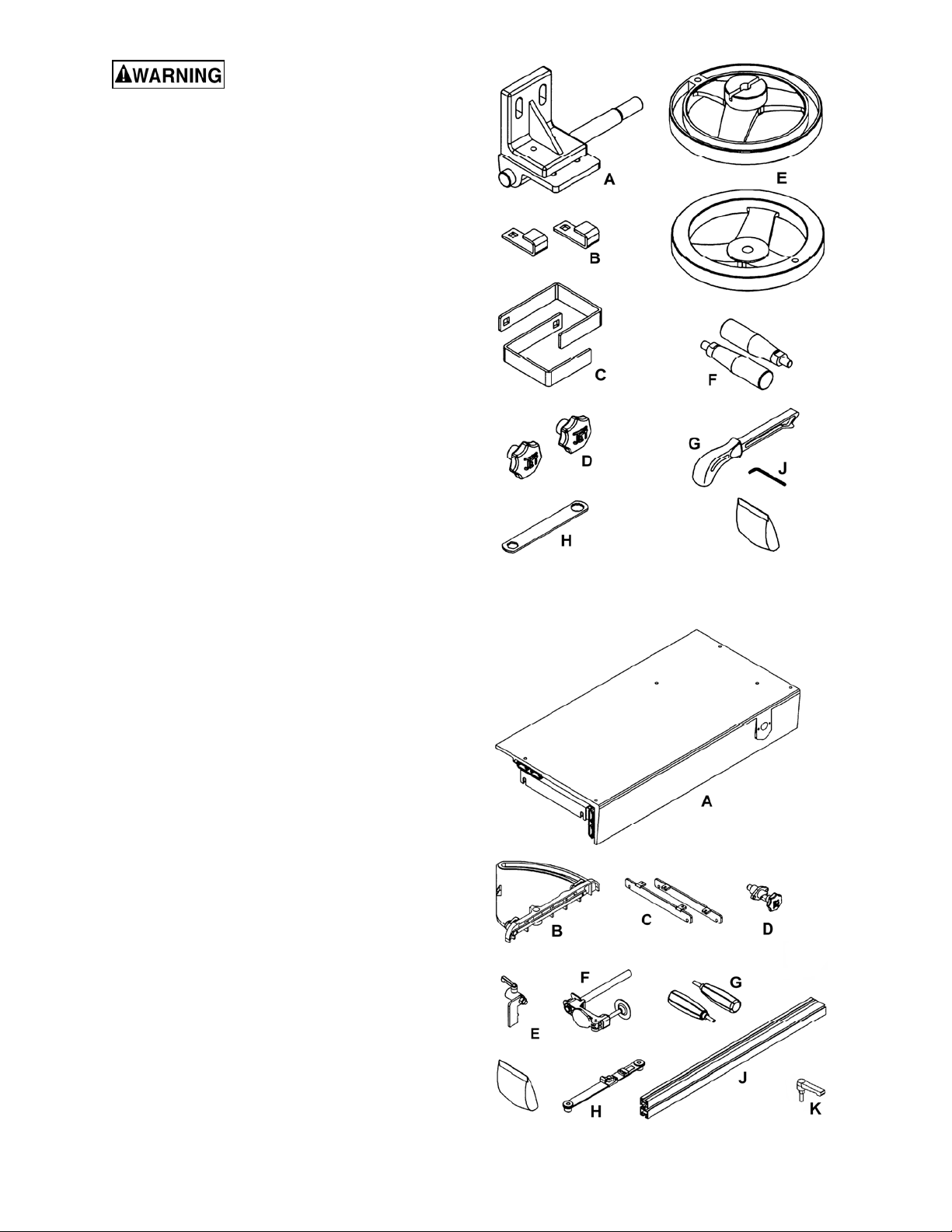
Accessory Package Box
1 Splitter Guard Assembly (A)
2 Miter Gauge Hooks (B)
2 Fence Hooks (C)
2 Handwheel Knobs (D)
2 Handwheels (E)
2 Handles (F)
1 Push stick (G)
1 Arbor Wrench (H)
1 Hex Wrench 3mm (J)
Hardware Bag
4 Carriage Bolts M8x16
4 Flat Washers M8
4 Hex Nuts M8
4 Lock Washer M8
Contents of Accessory Package
Sliding Table Box (optional accessory)
1 Sliding Table (A)
2 Sliding Table Leveling Brackets (C)
1 Sliding Table Lock Knob Assembly (D)
1 Miter Gauge (B)
2 Miter Gauge Handles (G)
1 Miter Gauge Lock Handles (K)
1 Miter Gauge Fence (J)
1 Miter Gauge Indicator Bracket (H)
1 Miter Gauge Clamp (F)
1 Miter Gauge Stop (E)
2 90° Shims
2 Flat Shims
1 Locking Handle
Hardware Bag
4 Hex Head Screws M8x25
8 Flat Washers M8
4 Hex Nut M8
4 Socket Head Cap Screws M6x25
2 Hex Socket Button Screws M6x12
4 Hex Nut M6
1 Hex Wrench 2.5mm
Contents for Sliding Table Box
8
Page 9
Left Wing Extension Box (optional accessory)
1 Left Wing Extension w/Miter Slot
1 Miter Gauge
1 Miter Gauge Bar
1 Miter Gauge Handle
1 Miter Gauge Fence
Hardware Bag
4 Socket Head Cap Screws M10x90
4 Lock Washers M10
4 Flat Washers M10
1 Hex Wrench 8mm
XACTA Fence II Homeshop 30/52
Box One:
1 XACTA Fence II
1 Lock Lever Knob
Box Two:
1 Front Rail
1 Back Rail
1 Guide Tube
2 Black Plastic End Caps
Hardware Bag consisting of:
Quantities for 30" and 52" Rails
Tools Required for Assembly
1 8mm Box Wrench
1 10mm Box Wrench
1 12mm Box Wrench
2 13mm Box Wrench
1 14mm Box Wrench
1 17mm Box Wrench
2 10mm Open End Wrenches
1 #2 Cross Point Screwdriver
1 #3 Cross Point Screwdriver
1 2.5mm Hex Wrench
1 3mm Hex Wrench
1 4mm Hex Wrench
1 5mm Hex Wrench
1 6mm Hex Wrench
1 Straight Edge
1 Combination Square
1 Combination Square & Straight Edge
1 Electric Drill
1 1/4”, 3/16, 5/16” Drill Bits
2 4”-6” C-Clamps
Metric Wrench Set or 6”-8” Adjustable Wrench
Metric Hex Wrench Set
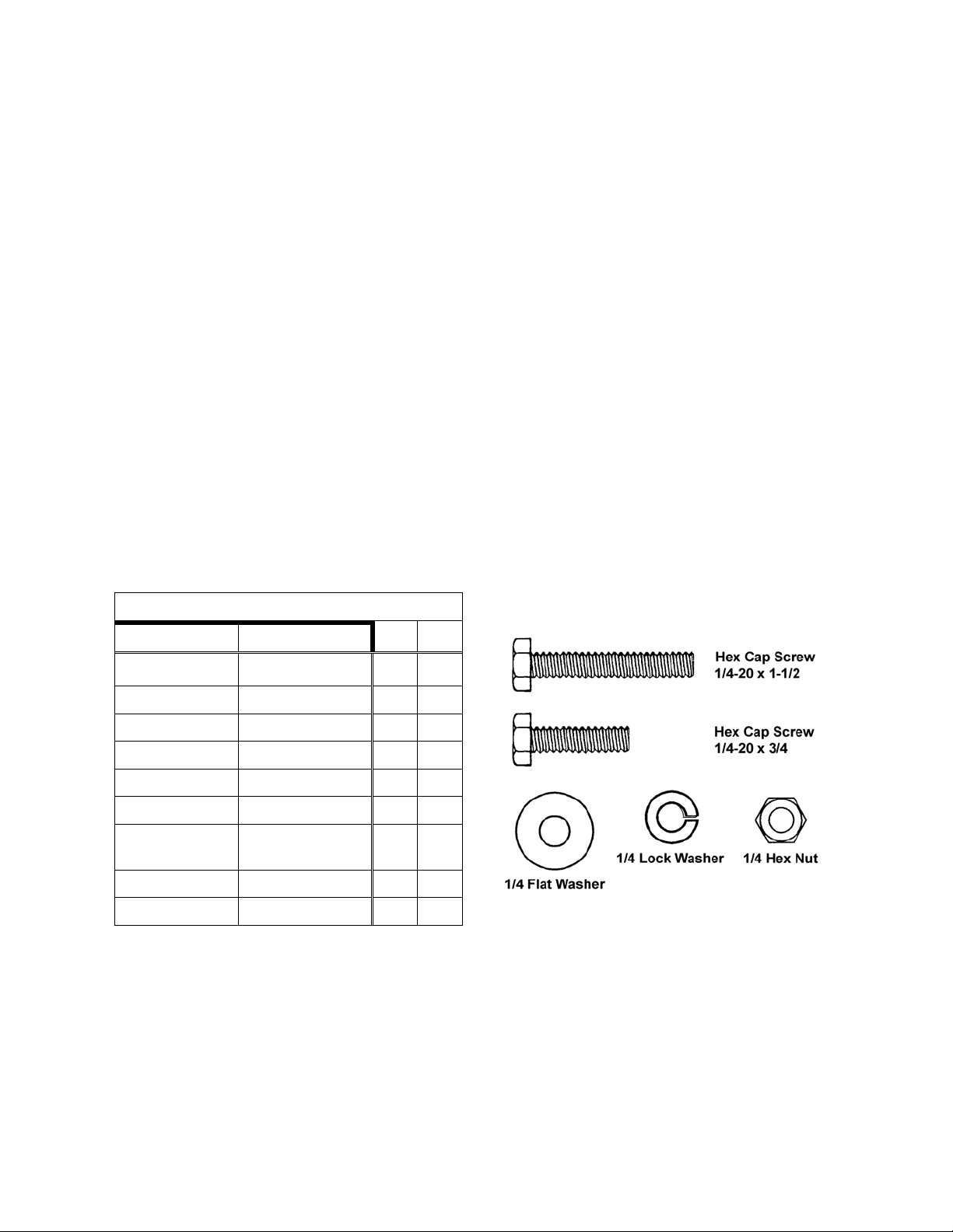
Size Part 30" 52"
1/4-20 x 1-1/2 Hex Cap Screws 06 07
1/4-20 x 3/4 Hex Cap Screws 05 07
1/4 Flat Washer 19 23
1/4 Lock Washers 13 16
1/4 Hex Nuts 06 07
1/4-20 x 1/2 Hex Cap Screws 02 02
M8 x 16
Notes: The hardware should be packed in the
guide rail along with the end caps.
The contents of the hardware bag (shown at right)
are drawn full scale.
Note 1: Quantities for items in the hardware bag
are for the 52" rail system. If you purchased the
30" rail system, there will be extra hardware.
Note 2: If the optional wooden extension table is
not used, there will be extra hardware.
Socket Head Cap
Screw
M8 Flat Washer 04 04
M8 Lock Washers 04 04
04 04
Contents of Hardware Bag
9
Page 10
Assembly
Unpacking and Clean-Up
Do not connect the table saw to
the power source until assembly has been
completed! Failure to comply may cause
serious injury!
• Tool: 12mm Wrench
1. Remove all contents from the shipping
container. Do not discard any shipping material
until the saw is set up and running
satisfactorily.
2. Carefully move saw to its final location.
3. Remove the dust baffle from the cabinet (refer
to page 30, Items 11 and 12).
4. Remove the hex cap screws from skid bottom.
5. With help from another person lift the saw off
the skid and into position.
6. Install the dust baffle in the cabinet.
Figure 1
Installation Requirements
The final location for the saw must be level, dry,
well lighted, and have enough room to allow
movement around the saw with long workpieces.
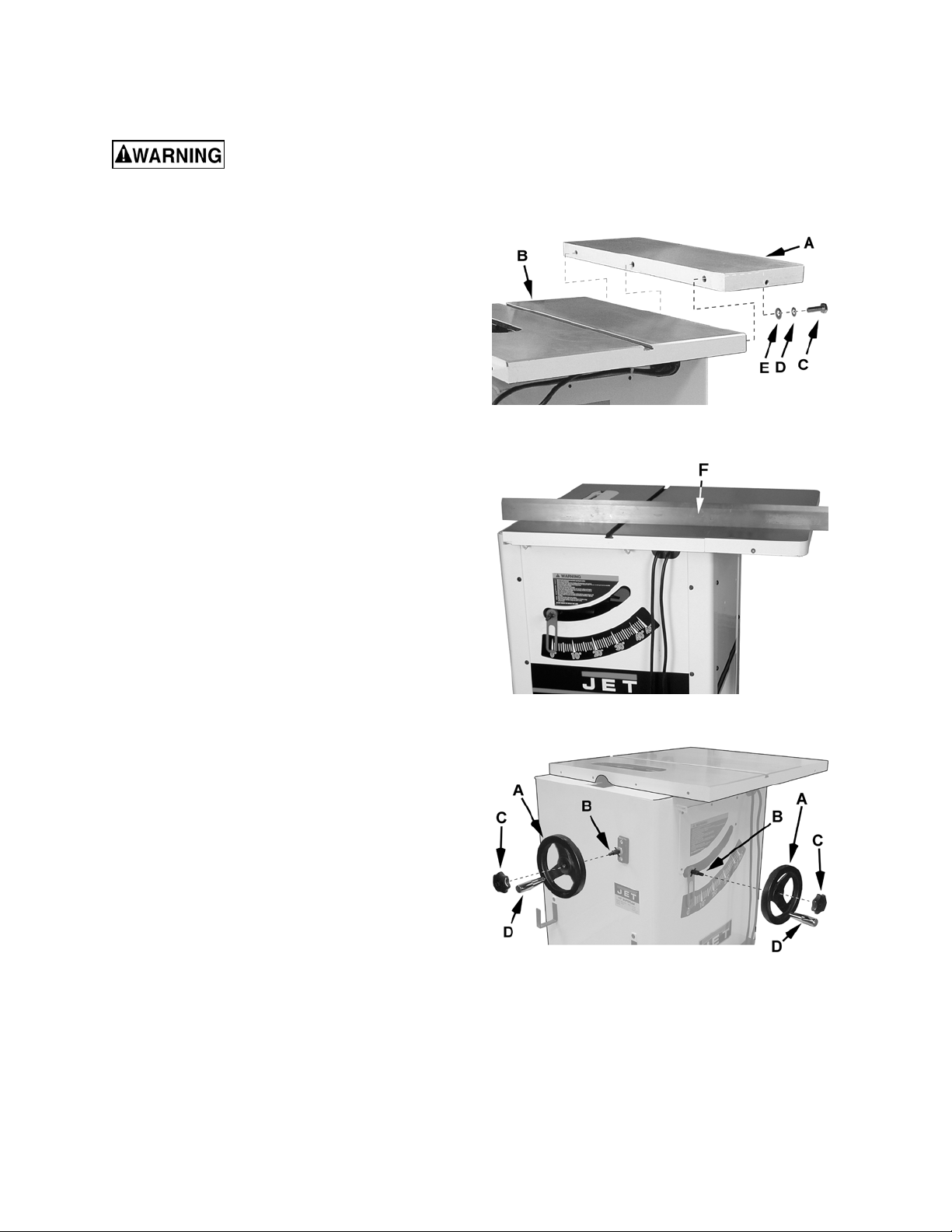
Right Extension Wing Assembly
Hardware: (3) M10x30 Hex Cap Screws, (3) M10
Lock Washers, (3) M10 Flat Washers & (1)
Extension Wing
Tools: 17mm Wrench, Straight Edge
Refer to Figures 1 and 2:
1. Attach right extension wing (A) to the table (B)
with three each hex cap screws (C), lock
washers (D) and flat washers (E). Snug but do
not tighten.
2. Slide extension wing toward the front edge of
the saw table until two faces are flush.
3. Using a straight edge (F, Fig. 2), align the
extension wings to the saw table and tighten
the hex cap screws.
Handwheel Assembly
Hardware: (2) Handles, (2) Handwheels & (2)
Lock Knobs
Tool: 14mm Wrench
Referring to Figure 3:
1. Slide the handwheel (A) onto the shaft (B);
make sure that the spring pin on the shaft lines
up with the slot on the handwheel.
Figure 2
Figure 3
2. Thread center lock knobs (C) into the shaft (B).
Note: The knobs will allow you to lock the
blade into a certain height, or angle.
3. Thread the handles (D) into the handwheels
and tighten with a wrench.
10
Page 11
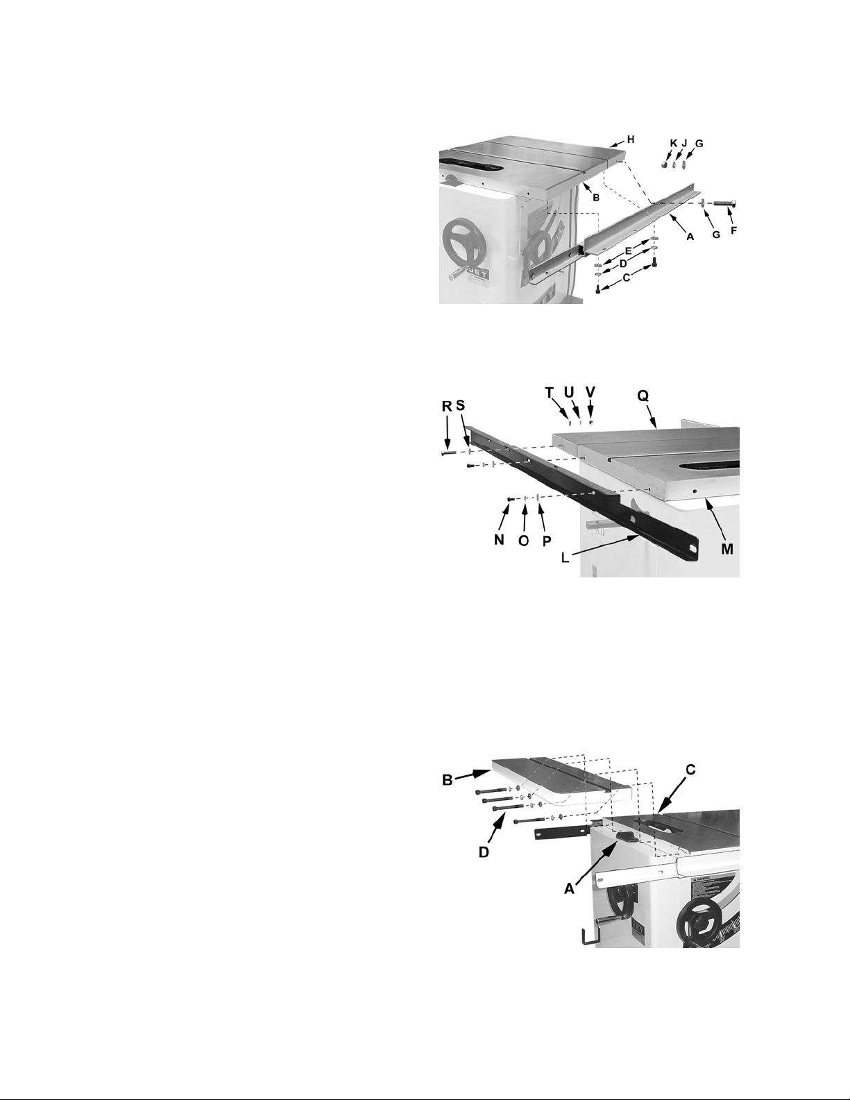
Mounting Rails
Hardware: Front Rail, Rear Rail, (4) M8x16
Socket Head Cap Screws, (4) M8 Flat Washers,
(4) Lock Washers, (2) 1/4-20 x 1-1/2 Hex Cap
Screws, (4) 1/4” Flat Washers, (2) 1/4” Lock
Washers, (2) 1/4” hex nuts.
Tools: 6mm hex wrench, two 13mm wrenches
Refer to Figures 4 and 5.
1. Mount the front rail (A) to the underside of the
table (B) with two socket head cap screws (C),
two lock washers (D), and two M8 flat washers
(E).
2. Insert a 1/4-20 x 1/2 hex cap screw (F) through
a 1/4” flat washer (G), the front rail (A) and
extension wing (H). Secure the screw to the
extension wing with a 1/4” washer (G), 1/4”
lock washer (J) and 1/4” hex nut (K).
3. Mount the rear rail (L) to the backside of the
table (M) with two socket head cap screws (N),
two lock washers (O) and two M8 flat
washers (P).
4. Insert a 1/4-20 x 1/2 hex cap screw (F) through
a 1/4” flat washer (G), the front rail (A) and
extension wing (H). Secure the screw to the
extension wing with a 1/4” washer (G), 1/4”
lock washer (J) and 1/4” hex nut (K).
Figure 4
Mounting Left Extension Wing with Miter Slot
Note: If you have a sliding table, skip this section
and proceed to the Mounting Sliding Table section.
Hardware: Left Extension Wing, (4) M10x90
Socket Head Cap Screws, (4) M10 Lock Washer,
(4) Flat Washers
Tools: Cross Point Screw Driver, Straight Edge,
Rubber Mallet, 8mm Hex Wrench
Referring to Figure 6:
1. Remove the arbor pulley guard (A). This is
only needed for the sliding table.
2. Attach left extension wing (B) to the table with
four socket head cap screws, four lock
washers and four flat washers (C). Snug but
do not tighten.
3. Slide extension wing toward the front edge of
the saw table until two faces are flush.
4. Place a straight edge across the table and left
extension wing. Align the extension wing the
same height as the saw table and tighten
socket head cap screws.
Figure 5
Figure 6
Note: Use a rubber mallet to align wing with
table.
11
Page 12
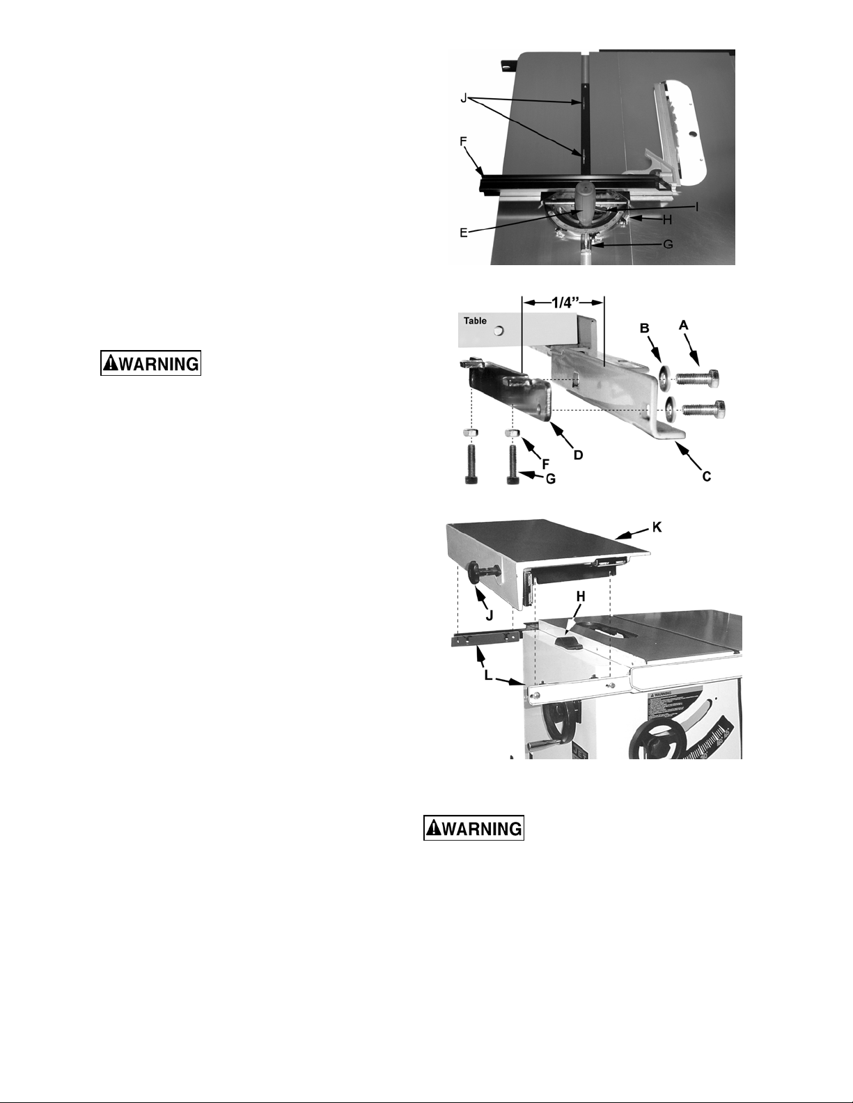
Miter Gauge for Left Extension Wing
Hardware: Miter Gauge
Tools: Cross Point Screw Driver, Square
1. Change the angle on the miter gauge by
loosening handle (E, Fig. 7) and turning the
fence (F, Fig. 7) to desired angle. To move
gauge beyond index stops of 45° and 90°, flip
back the stop (G, Fig. 7).
2. Adjust index stops by turning one of three
adjustment screws (H, Fig. 7). Use a square
to verify that the fence is 90° to the saw blade,
see Figure 7.
3. Slide fence to the left, or right by loosening
handle (I, Fig. 7). Make sure fence does not
interfere with the blade when cutting.
The fence on the miter gauge
must not contact the saw blade! Failure to
comply may cause serious injury!
Note: You can adjust the play in the miter gauge
by tightening the set screws (J, Fig. 7).
Note: Always make test cuts to verify the angle.
Mounting Sliding Table
Figure 7
Figure 8
Hardware: Sliding Table, (4) M8x25 Hex Cap
Screws, (4) M8 Hex Nuts, (8) M8 Flat Washers, (4)
M6 Hex Nuts, (4) M6x25 Socket Head Cap
Screws, (2) Flat Shims & (2) 90° Shims
Tools: Straight Edge, (2) 13mm Wrenches, 10mm
Wrench, 5mm Hex Wrench
Referring to Figure 8:
The procedure for installing the leveling brackets is
the same for front rail and back rail. The illustration
(Figure 8) shows the front rail.
1. Thread two M6 hex nuts (F) all the way onto
the four M6x25 socket head cap screws (G)
and thread the screws into the leveling
bracket (D).
2. Place two washers (B) on two M8x25 hex cap
screws (A). Insert through the mounting slots
of the front rail (C) and secure to the threaded
holes of the leveling bracket (D). Position the
leveling bracket (D) to be about 1/4” from the
front rail (C).
3. Install the remaining leveling bracket onto the
back rail repeating the procedure outlined in
Steps 1 and 2.
Note: The arbor pulley guard (H, Fig. 9) should
already be attached to the saw cabinet.
4. Mount table lock knob (J, Fig. 9) to the sliding
table (K, Fig. 9) with two M6x12 socket head
screws. Rotate knob 90° to engage/disengage
Figure 9
the lock.
Make sure that the lock knob is
in the locked position and that
the table is locked (does not slide on its support
plate). Failure to do so could result in injury
when attempting installation!
Read steps 5-7 carefully before attempting to mount
the sliding table.
5. Ensure that there is approximately a 1/4” gap
between rails and the brackets (C & D, Fig. 8)
so that you can set the sliding table in position.
6. Place the sliding table (K, Fig. 9) onto the
leveling brackets (L, Fig. 9).
12
Page 13
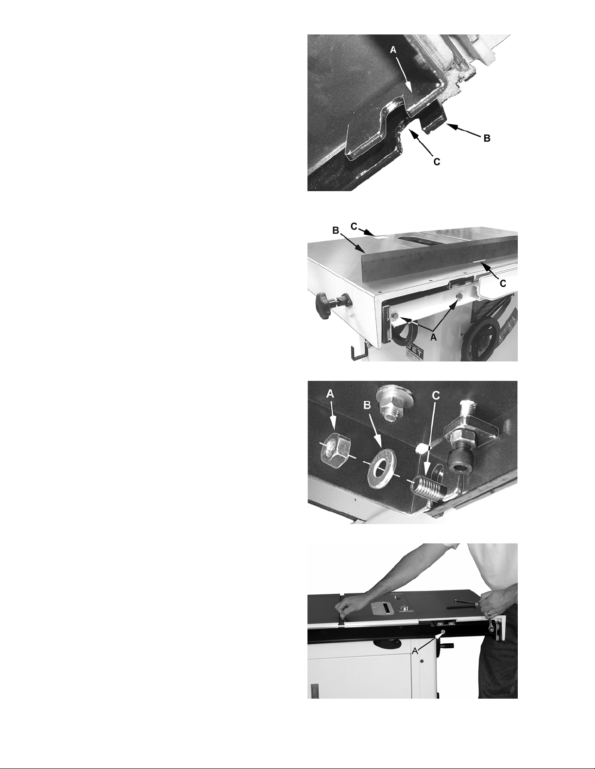
The support plate underneath the sliding table
(Figure 10) has an inner tab (A) and an outer
tab (B). When placing the table onto the
leveling bracket (D, Fig. 8), the leveling bracket
must be positioned between the inner and
outer tabs and the slots in the tabs (C, Fig. 10)
must straddle the screws (A, Fig. 8) that
secure the leveling bracket (D, Fig. 8) to the
rail (C, Fig. 8).
7. The sliding table should rest on the jacking
screws (G, Fig. 8).
8. Place two 90° 0.02” shims between the sliding
table and the table saw table near each end.
This will help keep the sliding table parallel to
the table saw table maintaining the proper
clearance.
9. Lower, or raise jacking screws (G, Fig. 8) so
that the sliding table surface is approximately
flush, or slightly lower than table saw table
surface.
10. Snug the four hex cap screws (A, Fig. 11) but
do not tighten. This will allow you to fine tune
the sliding table with the jacking screws.
Figure 10
11. Place a flat 0.02” shim (C, Fig. 11) on the table
saw tabletop for the straight edge (B, Fig. 11)
to rest on. This will help keep the sliding table
the right height above the top of the table saw.
12. Use two jacking screws (G, Fig. 8) to raise the
sliding table until it contacts the straight edge.
The straight edge should rest flat on sliding
table and shims.
13. Move straight edge to the other end of the
table saw tabletop and repeat step 12.
14. Tighten hex nuts (F, Fig. 8) against the leveling
bracket tabs while keeping jacking screws
(G, Fig. 8) from turning.
15. Tighten the four hex cap screws (A, Fig. 11)
that hold the leveling brackets in place.
Note: When tightening the screws on the rear
rail you may need to hold the sliding table
against the shims because there is a tendency
for the sliding table to move away from the
shim (Figure 12).
16. Verify that the jack screws (G, Fig. 8) contact
the sliding table support plate (Fig. 12).
Figure 11
Figure 11A
17. Place M8 flat washers (A, Fig. 11A) and M8
hex nuts (B, Fig. 11A) on the four screws
(C, Fig. 11A). Using two 13mm wrenches,
tighten the hex nuts while holding the screw
heads.
18. Remove the shims and make sure the sliding
table is still approximately 0.02” higher than
the table saw tabletop; it is still approximately
0.02” away from the table saw tabletop.
Figure 12
13
Page 14
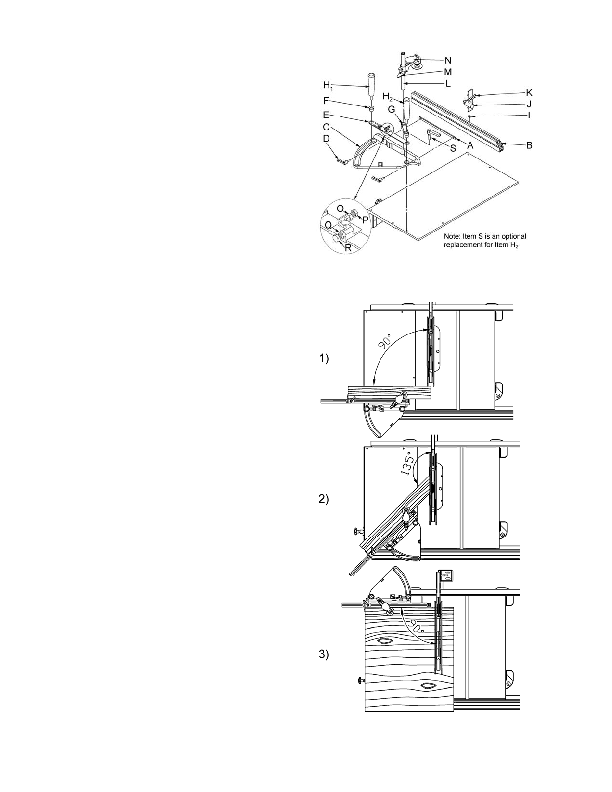
Sliding Table Miter Gauge
Hardware: Miter Gauge, Fence, (2) Handles,
Stop, Fence Bar, Indicator Bar, Bushing, Bracket
Clamp Assembly & (2) Handles
Tools: 2.5mm Hex Wrench
1. Slide the miter gauge fence (B, Fig. 13) into
the bar (A, Fig. 13) and attach to the miter
gauge body (C, Fig. 13) with two handles
(D, Fig. 13).
Note: the 45° mitered end of the miter gauge
fence should be on the side of the blade.
2. Place miter gauge on the sliding table. There
are three sets of threaded holes.
• (1, Fig. 14) One set of threaded holes, up
front to the far left, are for 90°-45° cutting.
• (2, Fig. 14) The staggered set of threaded
holes, up front to the right, are for 90°-135°
cutting. Note: using this position with the
blade tilted to 45° you need to remove the
miter gauge handle found on the right side
and replace with the supplied 90° handle.
• (3, Fig. 14) The set of threaded holes, on
the far side, are used for cutting at 90°.
Referring to Figure 13:
3. Place indicator bar (E) on top of the miter
gauge body and secure in place with bushing
(F), bracket (G) and handles (H).
Figure 13
4. Slide the square nut (I) into the slot on top of
the fence. Secure the stop (J) in place with a
handle (K).
5. Slide clamp bar (L) into the bracket, and miter
gauge. Tighten set screw found in the bracket.
Pull up on the quick release (M) and slide the
clamp on to the bar. Position clamp disc
against the workpiece and pull the clamp lever
(N) towards you.
6. Use a square to make sure miter gauge is 90°
to saw blade. If you need to make an
adjustment. Loosen hex nut (O) found on
indicator bar and turn bolt (P) until it rests
against the miter gauge. Tighten the nut.
Adjust cursor if necessary.
7. Use a combination square to make sure miter
gauge is 45° to the saw blade. If you need to
make an adjustment. Loosen hex nut (Q)
found on the indicator bar and turn bolt (R)
until it rests against the miter gauge. Tighten
the nut. Adjust cursor if necessary.
Figure 14
14
Page 15

Mounting the Switch Assembly
Hardware: (2) 1/4x1/2 Hex Cap Screws,
(2) 1/4 Lock Washers, (2) 1/4 Flat Washers.
Tool: 4mm Hex Wrench
Referring to Figure 15:
Mount the switch assembly (A) to the bottom side
of the front rail (B) with two button head cap
screws (C) and two washers (D).
Note: The switch assembly can be installed in
various locations along the front rail.
On-Off Switch Padlock
Model No. BP-1, Stock No. 709736
To safeguard your machine from unauthorized
operation and to avoid accidental starting by young
children, the use of a padlock is highly
recommended. JET model BP-1 is available from
your local authorized JET distributor or by calling
JET Equipment & Tools at 800-274-6848.
Wooden Extension Table
The wooden extension table is an optional
accessory.
Hardware: (4) C-clamps
Tools: Electric drill, Cross point screwdriver, two
10mm wrenches, Straight edge, Hammer (or
rubber mallet)
Installation
The optional wood extension table (including the
optional router table) sits flush against the saw
table and along the inside of the rails. The JET
logo (or warning label on the router table) should
face outward. The extension table is not bolted to
the saw table, it is bolted only to the rails.
Figure 15
Figure 16
The extension table and saw table must be aligned
properly so the XACTA-FENCE II™ will slide
smoothly from one to the other.
1. Place the extension table between the rails
and up against the saw table, leaving the
extension table raised just slightly above the
saw table. Clamp the extension table to the
front and back rails as shown in Figure 16.
Clamping pressure should be enough to
secure the table yet allow minor adjustments.
2. Use a hammer and block of wood (or a rubber
mallet) to tap the extension table up flush
against the cast iron saw table (Figure 16).
Then tap down the extension table at various
points along its edge where it meets the saw
Figure 17
15
Page 16

table, until it is level with the saw table
(Figure 17). As one part of the edge becomes
level with the table, tighten the clamp on that
side. Then move to the other side and repeat,
until the full length of the edge is level with the
saw table. Lay a straight edge across both
extension table and saw table to ensure proper
leveling.
When the extension table is properly aligned, holes
need to be drilled into the wood table using the
holes in the rails as your guide (Figure 18). You
may wish to drill 3/32" pilot holes first.
3. Drill 1/4" holes into the front edge of the table
using the holes in the front rail as a guide. Drill
1/4" holes into the back edge of the table using
the holes in the back rail as a guide.
If you have a 30” Rail System go to Step 4. For a
52” Rail System, go to Step 5.
4. Install two 1/4-20 x 1-1/2 hex cap screws, four
1/4 flat washers, two 1/4" lock washers and
two 1/4 hex nuts into the holes in the front
edge of extension table as shown in Figure 19.
Finger-tighten only. Then go to Step 6.
Figure 18
If you have a 52” Rail System:
5. Install three 1/4-20 x 1-1/2 hex cap screws, six
1/4 flat washers, three 1/4" lock washers and
three 1/4 hex nuts into the holes in the front
edge of extension table as shown in Figure 19.
Finger-tighten only.
6. Repeat Step 4 (or 5) for the back rail.
Note: The back edge of the extension table
requires two 1/4-20 x 1-1/2 hex cap screws,
four 1/4 flat washers, and two each 1/4" lock
washers and 1/4 hex nuts for 30” and 52” rails.
7. Re-check the table for alignment, make further
adjustments if necessary, then tighten all
screws and nuts.
8. Mount the two legs to the inside corners of the
extension table as shown in Figure 20. Secure
with the eight screws provided.
Note: If you are using a mobile base under your
saw, you may need to shift the placement of the
legs so they rest properly upon the shelves of the
base.
9. Adjust the footpads on the legs
counterclockwise until they reach the floor,
then tighten the nut.
Figure 19
Figure 20
Guide Tube
The guide tube is placed on top of the front rail and
is mounted with the black unpainted surface
positioned toward the operator.
If your left table wing is the "fixed" type with miter
16
Figure 21
Page 17

slot (A. Fig. 21), orient the guide tube (B) with
respect to the rail (C) as shown in Figure 21.
If your left table wing is the sliding table type
(D, Fig. 22), mount the guide tube (F) so it lines up
with the left edge on the angle iron portion of the
rail (E).
Referring to Figure 23:
1. Align the holes in the bottom of the guide
tube (G) with the holes in the front rail (H).
2. Fasten the guide tube (G) to the rail (H) from
beneath with 1/4-20 x 3/4 hex cap screws (J),
1/4 lock washers (K) and 1/4 flat washers (L).
Finger-tighten only.
3. Instructions for the installation of the scale on
the guide tube is given after the XACTA fence
has been assembled and given a preliminary
adjustment.
Figure 22
Figure 23
XACTA Fence
Screw the lock lever knob into the threaded handle
on the XACTA Fence II as shown in Figure 24.
The lock lever has three functional positions as
shown in Figure 25:
• The upright position permits mounting and
removal of fence from the saw.
• The unlock position permits easy fence
positioning.
• The lower position locks the fence to the
front rail. The cam handle should be
pushed down firmly against the pin.
Fence Adjustments
Note: Fence adjustments should be performed in
the order given.
Level with the Saw Table Adjustment
1. Place the fence on the table and lock it.
Figure 24
Figure 25
2. View the fence from the left side of the saw.
Look for the space between the table and the
fence bottom to be equal along the entire
length of the fence (Figure 26).
3. If adjustment is necessary, unlock the fence.
Figure 26
17
Page 18

4. Raise or lower two nylon adjustment screws
(A, Fig. 27) the same number of turns until the
space between the bottom of the fence and the
table is the same. Care must be taken to raise
or lower the fence on each side equally or the
fence may not be 90° to the table after the
height adjustment is performed.
Parallel to the Miter Slot Adjustment
1. Place the fence next to the outside edge of the
right miter slot and lock it.
2. The fence should be even with the miter slot
from front to back.
3. If the fence is not even along the length of the
miter slot, unlock the fence, remove it and turn
upside down (Figure 28).
4. Adjust one of the two set screws (A, Fig. 28)
until the fence is even with the miter slot edge
along its entire length when locked.
Note: You may need to re-adjust the clamping
pressure after aligning the fence.
Clamping Pressure Adjustment
The XACTA Fence II has been adjusted at the
factory to lock securely when the lock handle is
pushed down. If adjustment is needed:
1. Unlock the fence.
2. Remove the fence from the guide rail.
3. Turn the fence over.
4. Adjust each of the two set screws (A, Fig. 28)
exactly the same number of rotations until the
fence is held securely when the lock handle is
pushed down.
A clockwise rotation of the set screws will increase
the cam pressure. Counterclockwise rotation will
decrease cam pressure.
90° to the Table Adjustment
1. Place the fence on the saw table and lock it.
2. Place a square (A, Fig. 29) on the table next
to the fence. The fence should be 90° to the
table.
3. If adjustment is necessary, unlock the fence,
and turn one of the two nylon adjustment
screws (B, Fig. 29) until the fence is 90° to the
table.
4. Lock the fence and check the adjustment
again.
Initial Cursor Pre-adjustment
Loosen two screws securing the cursor to the
fence and adjust the cursor to midrange. This will
provide sufficient range for later adjustment if
required.
Figure 27
Figure 28
18
Figure 29
Page 19

Installing the Blade
When installing or changing
saw blade, always disconnect saw from power
source! Failure to comply may cause serious
injury!
Hardware: Blade
Tools: Arbor Wrench, Scrap Piece of Wood
1. Raise the blade arbor and make sure the arbor
is at the zero degree position.
2. Remove the arbor nut (A, Fig. 30) and flange
(B, Fig. 30).
3. Place blade (C, Fig. 31) on arbor shaft making
sure teeth point down at the front of the saw.
Replace flange and arbor nut.
4. Place a wood scrap in the blade's teeth at the
rear of the machine. Hold the block of wood in
such a way that if it slips or the blade turns,
your hand will not contact the blade, Figure 31.
5. Using the wrench provided, securely tighten
the arbor nut. Remove the wrench.
Guide Tube Scale Application
Refer to Figures 32 and 33.
Figure 30
Figure 31
The scale for the guide tube comes rolled, with an
adhesive backing and must be applied to the guide
tube as follows:
1. Place the fence (A) so it is flush against the
right side of the saw blade (B) and lock it.
2. Using a fine marker, place a mark on the guide
tube at the cursor hairline (C).
3. Remove the fence (A).
4. Remove the protective backing from the
scale strip (D).
5. Apply the scale strip (D) onto the guide tube at
the outlined location (E), making sure to line up
the "zero" mark (F) on the scale with the mark
on the guide tube (G) previously determined in
Step 2.
If further adjustment is required, see the Cursor
Adjustment instructions in the Adjustments section.
Figure 32
Figure 33
19
Page 20

Blade Guard Assembly
Hardware: Blade Guard Assembly, Splitter Guard
Assembly
Tools: 12mm Wrench, 17mm Wrench or
Adjustable Wrench, 3mm Hex Wrench
1. With a 3mm hex wrench, loosen two set
screws (G, Fig. 34) on the splitter guard
assembly and remove the bracket.
2. Remove the hex nut and lock washer from the
threaded end of blade guard shaft and reverse,
threading the hex nut first, then placing the
lock washer on the shaft.
3. Thread the blade guard shaft (E, Fig. 34) into
rear trunnion through opening at rear of saw.
4. Tighten blade guard shaft. The shaft has a
hole to accommodate a screwdriver.
5. Place upper and lower bracket assembly
(F, Fig. 34) in the upright position and snug
two set screws (G, Fig. 34) just enough to hold
in place.
6. Insert front tab (A, Fig. 35) of blade guard
assembly through insert opening in the table.
Loosen the hex cap screw already installed at
the factory and insert the front tab of the blade
guard. The tab is held in place between the
flat washer and bracket. Leave a 1/8” gap
between the splitter and table. Tighten hex
cap screw
Note: make sure the anti-kickback pawls
(B, Fig. 35) are pointing towards the back of the
saw.
7. Secure rear tab of blade guard assembly to the
upper blade guard bracket with two hex cap
screws (C, Fig. 35). Leave a 1/8” gap between
the splitter and table. Tighten hex cap screws.
Figure 34
Figure 35
Figure 36
Table Insert Adjustment
Hardware: Table Insert
Tools: Straight Edge, 3mm Hex Wrench
1. Adjust table insert (A, Fig. 36) flush with table
by turning four leveling screws (B. Fig. 36).
2. Use a straight edge (C, Fig. 36) to make sure
the insert is flush with the table.
Aligning Blade Guard and Splitter
Tools: 12mm Wrench, 3mm Hex Wrench, Straight
Edge
1. Use a straight edge (E, Fig. 37) to align the
splitter with the saw blade. Be sure the
straight edge rests against the body of the saw
blade and not the saw teeth.
Figure 37
2. Tighten two set screws (G, Fig. 34) on the
bracket assembly.
3. Make sure the splitter is level with the table and
approximately 1/8" above the table. The space
between the splitter and the table keeps the
splitter from binding on the table when the
blade is tilted to 45°.
20
Page 21

Hooks for Miter Gauge and Fence
Hardware: (2) Miter Gauge Hooks, (2) Fence
Hooks, (4) M8x16 Carriage Bolts, (4) M8 Flat
Washers, (4) M8 Lock Washers & (4) Hex Nuts
Tool: 13mm Wrench
1. Mount the two fence hooks (A, Fig. 38) with
two M8x16 carriage bolts, two M8 flat washers,
two M8 lock washers and two M8 hex nuts.
Helpful Hint: Removing the rear access door
by pulling the release lever (E, Fig. 40) will
facilitate reaching the front hook mounting
hole.
2. On the opposite side of the cabinet mount two
miter gauge hooks with two M8x16 carriage
bolts, two M8 flat washers, two M8 lock
washers and two M8 hex nuts.
Blade Raising and Tilting Mechanism
1. To raise or lower saw blade, loosen the lock
knob (A, Fig. 39) and turn the handwheel
(B, Fig. 39) on the saw front until desired
height is reached. Tighten lock knob. The
blade should be adjusted 1/8" to 1/4" above
the top surface of the material being cut, about
3-5 blade tips.
Figure 38
2. To tilt the saw blade, loosen lock knob found
on the left side of the table saw and turn
handwheel until desired angle is obtained, then
tighten lock knob.
Electrical Connections
A qualified electrician must complete all
electrical connections! Failure to comply
may result in serious injury!
The JWSS-10CS table saw is rated at 1-3/4 HP,
1Ph, 115V/230V prewired 115V.
To switch the JWSS-10CS from 115V to 230V:
1. Disconnect the machine from the power
source, (unplug).
2. Open the cabinet door found on the rear of
the saw, by pressing the red release button
on the latch assembly. Lift the lever up and
pull the door open.
3. You can remove the door by pulling the
door release lever down (E, Fig. 40).
4. Remove the cover from the motor junction
box (F, Fig. 40).
Figure 39
5. Change wires following the diagram on the
inside of the cover.
6. Replace the cover and close the cabinet
door.
Confirm power at the site is the same as the saw
before making any electrical connections.
Review the Wiring Diagrams on pages 43-44.
Using extension cords can cause a loss in
power to your machine. It is best if the saw is
plugged directly into an outlet on a dedicated
circuit.
Figure 40
21
Page 22

Grounding Instructions
This tool must be grounded
while in use to protect the operator from
electric shock.
In the event of a malfunction or breakdown,
grounding provides a path of least resistance for
electric current to reduce the risk of electric
shock. This tool is equipped with an electric
cord having an equipment-grounding conductor
and a grounding plug. The plug must be
plugged into a matching outlet that is properly
installed and grounded in accordance with all
local codes and ordinances.
Do not modify the plug provided. If it will not fit
the outlet, have the proper outlet installed by a
qualified electrician.
Improper connection of the equipmentgrounding conductor can result in a risk of
electric shock. The conductor, with insulation
having an outer surface that is green with or
without yellow stripes, is the equipmentgrounding conductor. If repair or replacement of
the electric cord or plug is necessary, do not
connect the equipment-grounding conductor to a
live terminal.
Check with a qualified electrician or service
personnel if the grounding instructions are not
completely understood, or if in doubt as to
whether the tool is properly grounded. Use only
three wire extension cords that have three-prong
grounding plugs and three-pole receptacles that
accept the tool’s plug.
Repair or replace a damaged or worn cord
immediately.
230 Volt Operation
If 230V, single-phase operation is desired, the
following instructions must be followed:
1. Disconnect the machine from the power
source.
2. Turn the handwheel until the saw blade is in
the 45° position. This will allow easy access
to the motor junction box.
3. This table saw is supplied with four motor
leads that are connected for 115V operation,
as shown in Figure A. Reconnect these four
motor leads for 230V operation, as shown in
Figure B.
4. The 115V attachment plug (A), supplied with
the table saw, must be replaced with a
UL/CSA listed plug suitable for 230V
operation (D). Contact your local Authorized
JET Service Center or qualified electrician
for proper procedures to install the plug.
The table saw must comply with all local and
national codes after the 230-volt plug is
installed.
115 Volt Operation
Your table saw is set at the factory to run at 115volt operation. When wired for 115 volt, this
table saw is intended for use on a circuit that
has an outlet and a plug that looks like the one
illustrated in (A). A temporary adapter, which
looks like the adapter as illustrated in (B), may
be used to connect this plug to a two-pole
receptacle, as shown in (B) if a properly
grounded outlet is not available. The temporary
adapter should only be used until a properly
grounded outlet can be installed by a qualified
electrician. This adapter is not applicable in
Canada. The green colored rigid ear, lug, or
tab, extending from the adapter, must be
connected to a permanent ground such as a
properly grounded outlet box, as shown in (B).
5. The table saw with a 230-volt plug should
only be connected to an outlet having the
same configuration (D). No adapter is
available or should be used with the 230-volt
plug.
Important: In all cases (115 or 230 volts), make
certain the receptacle in question is properly
grounded. If you are not sure, have a registered
electrician check the receptacle.
22
Page 23

Adjustments
Blade Alignment
Tools: 8mm Hex Wrench, Combination Square &
Marker
Blade alignment with the miter slot is adjusted at
the factory. After a period of use, or after moving
the saw to another location, the blade may no
longer be aligned properly. To check and align the
blade, see Figure 41.
1. Disconnect saw from the power source,
unplug.
2. Raise the blade guard up and out of the way of
the blade.
3. Unlock fence and move away from the blade
so as to expose the right T-slot.
4. Choose a tooth on the far side of the blade and
directly over the insert. Mark the tooth with a
marker. Measure the distance from the side of
the blade to the right T-slot edge using a
combination square. Make sure to measure
between the teeth not on the tooth, see
Figure 41.
Figure 41
5. Rotate the blade toward the front so that the
marked tooth is just above the insert. Measure
the distance from the side of the blade to the
right T-slot edge. The two measurements
should be the same.
6. If they are not the same, loosen four hex head
screws (A, Fig. 42) that hold the trunnions to
the table. Two are shown in Figure 42.
7. Make the needed adjustments to the trunnion
assembly and tighten the four hex head
screws.
8. Check the alignment once again after
tightening hardware.
XACTA Fence Cursor Adjustment
This adjustment must be checked whenever a
different blade is installed.
1. Disconnect the table saw from the power
source.
2. Raise the saw blade above the tabletop.
3. Unlock the fence and slide it to approximately
four inches from the saw blade.
4. Lock the fence.
5. Measure the distance between the saw blade
and the inside of the fence.
Figure 42
Figure 43
6. Adjust the cursor (C, Fig. 43) to read the
distance just measured and tighten the cursor
assembly to the fence.
7. Take a test cut and confirm that the adjustment
is correct.
23
Page 24

Adjusting 45° and 90° Positive Stops
The stops have been adjusted at the factory. After
a period of use, or, after moving the saw to another
location, the stops may no longer be set properly.
To check and adjust the stops:
Tool: 12mm Wrench,
1. Disconnect saw from power source, unplug.
2. Raise the saw blade to its maximum height
using the handwheel.
3. Set the blade at 45° or 90° to the table by
turning the blade tilting handwheel clockwise
as far as it will go.
4. Place a square on the table and check to see
that the blade is at a 45° or 90° angle to the
table, see Figure 44. Make sure square is not
touching a blade tooth.
If blade is not at 90°
5. Referring to Figure 45, remove the front panel
(D) by unscrewing the lock knob (A), pulling off
the handwheel (B) and removing five pan head
screws (C) that hold the front panel.
6. Referring to Figure 46, loosen the lock nut (A)
and turn set screw (B) on the front trunnion in
or out. The set screw should stop against the
front trunnion bracket when the blade is 90° to
the table.
Combination Square
Figure 44
Figure 45
7. Tighten the lock nut (A) and recheck the blade
with a square (Figure 44).
8. Check the accuracy of the pointer (E) on the
angle scale and adjust, if necessary. Loosen
set screw (F) to change the pointer position.
If the blade is not 45°
9. Remove the front panel per Step 5. Loosen
lock nut (C, Fig. 46) and turn set screw (D, Fig.
46) on the front trunnion in or out. The hex
cap screw should stop against the table when
the blade is 45° to the table.
10. Check the accuracy of the pointer (E. Fig. 46)
on the angle scale and adjust, if necessary.
Loosen set screw (F, Fig. 46) to change the
pointer position.
Assembly and adjustment of the saw are now
complete. Make sure all fasteners are tight. The
saw may now be placed into operation.
Figure 46
Figure 47
24
Page 25

Wear Adjustment in Raising Mechanism
As the worm gear wears with time you may notice
a little play in the handwheel. To adjust for wear in
the raising mechanism:
1. Disconnect the machine from the power
source, unplug.
2. Referring to Figure 48, remove the front panel
(D) by unscrewing the lock knob (A), pulling off
the handwheel (B) and removing five pan head
screws (C) that hold the front panel.
3. Use a wire brush and a cleaner/degreaser to
clean worm shaft, and trunnions. Apply white
lithium grease or powdered graphite to
lubricate worm shaft, and trunnions.
Referring to Figure 49:
4. Loosen lock nut (A).
5. Turn eccentric sleeve slightly (B) by placing
the wrench on the flat surface of the eccentric
sleeve located just behind the gear (C). Adjust
so that the worm raises into the worm gear
removing play in the teeth (H). After the worm
and worm gear touch back off slightly to leave
a little backlash between teeth. Tighten the
nut and try the handwheel. Make any
necessary adjustments.
Figure 48
6. Tighten lock nut (A).
Wear Adjustment in Tilting Mechanism
As the worm gear wears with time you may notice
a little play in the handwheel. To adjust for wear in
the tilting mechanism (while referring to Figure 50):
1. Disconnect the machine from the power
source, unplug.
2. Open the rear cabinet door and remove the
poly v-belt by lifting up on the motor.
3. Use a wire brush and a cleaner/degreaser to
clean worm shaft, and trunnions. Apply white
lithium grease or powdered graphite to
lubricate worm shaft, and trunnions.
4. Loosen lock nut (I).
There is a flat area on the eccentric sleeve that
accommodates a wrench for adjustments.
5. Turn eccentric sleeve slightly (J) so that the
worm raises into the worm gear removing play
in the teeth (K). After the worm and worm gear
touch back off slightly to leave a little backlash
between teeth. Tighten the nut and try the
handwheel. Make any necessary adjustments.
6. Tighten lock nut (I).
Figure 49
Figure 50
25
Page 26

Changing Poly V-Belt
Make all machine adjustments or maintenance
with the machine unplugged from the power
source. Failure to comply may cause serious
injury!
1. Disconnect the machine from the power
source, unplug.
2. Lower the blade to its lowest point and tilt to
45°. This will allow easy access to the poly vbelt.
3. Take the tension off of the belt (A, Fig. 51) by
lifting up on the motor.
4. Remove the belt from the arbor and motor
pulleys.
5. Replace the belt. The weight of the motor and
the torsion spring should apply enough tension
to the belt.
Figure 51
Changing the Transfer Belt
Referring to Figures 52 and 53:
1. Disconnect the machine from the power
source, unplug.
2. Remove the front panel (D) by unscrewing the
lock knob (A), pulling off the handwheel (B),
and removing five pan head screws (C) that
hold the front panel.
3. Remove bolt (F) and pivot assembly up to take
the tension off the belt. Take belt off the upper
pulley. Remove nut (G) and pull off the
assembly.
4. Remove the screw and washer (H) that holds
the shaft (I) in place.
5. Loosen the two set screws (J) that hold the
timing pulley in place.
6. Pull out the shaft far enough so that you can
remove the timing belt (K).
Figure 52
7. Replace with a new belt and reassemble.
8. Make sure timing pulleys are aligned and
tighten set screws (J).
9. Make sure tension on the timing belt is enough
so that the belt does not slip. Tighten bolt (F).
26
Figure 53
Page 27

Maintenance
General Maintenance
Cabinet and Motor: Keep the inside of the
cabinet clear of sawdust and wood chips. Vacuum
out the inside of the cabinet and blow out the
inside with an air hose. Make sure the motor fan
and fan cover are also kept clear of sawdust.
Worm Shafts and Trunnions: Use a wire brush
and a cleaner/degreaser to clean worm shaft, and
trunnions. Apply white lithium grease or powdered
graphite to lubricate worm shaft, and trunnions.
Sliding Table: After a days use push the sliding
table all of the way forward and wipe out any
sawdust that may have made it past the wipers.
The important part of the bearing sliders is the
mating grooves (A, Fig. 54) that the bearings ride
along.
Pull the sliding table all of the way forward and
wipe out any sawdust that may have made it past
the wipers. The important part of the bearing
sliders is the mating grooves (A, Fig. 55) that the
bearings ride along.
Figure 54
Add a small amount or lightweight oil to the
bearing grooves, if necessary and run the sliding
table back and forth to work the oil into the
bearings. Wipe off any excess oil.
Table Top: Remove rust from the tabletop with
WD-40 and a Scotch-Brite™ Hand Pad. Keep a
light coat of WD-40 on the tabletop when not in
use.
Blades and Accessories
10” x 40T carbide ..................................... 709733
10” x 60T carbide ..................................... 709734
Feather board...........................................709721
JTG-10Q Tenoning Jig............................. 708295
Tenoning Jig Adaptor Plate................. 708295SS
Tenoning Jig Kit* ...............................708295SSK
XACTA Lift................................................708124
Outfeed Rollers ................................... 708150PK
Universal Mobile Base .............................708119
*Consists of JTG-10Q Tenoning Jig and Adaptor Plate
Figure 55
27
Page 28

Troubleshooting
Trouble Possible Cause Solution
Saw stops or will
not start
1. Overload tripped
2. Saw unplugged from wall or motor
3. Fuse blown or circuit breaker
tripped
4. Cord damaged
5. Starting Capacitor is bad
6. Centrifugal Switch bad or out of
adjustment
1. Allow motor to cool and push reset
button found on “On/Off” Assembly
2. Check all plug connections
3. Replace fuse or reset circuit breaker
4. Replace cord
5. Replace Starting Capacitor
6. Replace or adjust Centrifugal Switch
Does not make
accurate 45° or
90° cuts
Material binds
blade when
ripping
Saw makes
unsatisfactory
cuts
Blade does not
come up to
speed
Saw vibrates
excessively
1. Stops not adjusted correctly
2. Angle pointer not set accurately
3. Miter gauge stops out of
adjustment
1. Fence not aligned with miter slot
2. Warped wood
3. Excessive feed rate
4. Splitter not aligned with blade
1. Dull blade
2. Blade mounted backwards
3. Gum or pitch on blade
4. Incorrect blade for cut
5. Gum or pitch on table
1. Extension cord too light or too long
2. Low shop voltage
3. Motor not wired for correct voltage
1. Stand on uneven floor
2. Damaged saw blade
3. Bad Poly V-belt
4. Loose hardware
1. Check blade with square; adjust stops
2. Check blade with square adjust
pointer
3. Adjust miter gauge stops
1. Check and adjust fence parallel to
miter slot
2. Select another piece of wood
3. Reduce feed rate
4. Align splitter with blade
1. Sharpen or replace blade
2. Turn blade around
3. Remove blade and clean
4. Change blade to correct type
5. Clean table
1. Replace with adequate size cord
2. Contact your local electric company
3. Refer to motor junction box
1. Move to an even level floor
2. Replace saw blade
3. Replace Poly V-belt
4. Tighten hardware
Material kicked
back from blade
Blade does not
raise or tilt freely
Sliding Table
does not move
smoothly
1. Rip fence out of alignment
2. Splitter not aligned with blade
3. Feeding stock without rip fence
4. Splitter not in place
5. Dull blade
6. Letting go of material before it is
past blade
7. Anti-kickback plates dull
1. Sawdust in raising and tilting
mechanisms
1. Saw dust in the bearing sliders. 1. Wipe out any sawdust that may have
28
1. Align rip fence with miter slot
2. Align splitter with blade
3. Install and use rip fence
4. Install and use splitter (with guard)
5. Replace blade
6. Push material all the way past blade
before releasing work
7. Replace or sharpen anti-kickback
plates
1. Clean and regrease
made it past the wipers. The
important part of the bearing sliders is
the mating grooves that the bearings
ride along
Page 29

Parts
XACTA Fence II Homeshop 30/52 Fence Assembly
Index No. Part No. Description Size Qty
1 ...............HF2-101 ...................Left Side Plate...................................................... .................................... 1
2 ...............HF2-102 ...................Fence Body Assembly ......................................... .................................... 1
3 ...............HF2-103 ...................Tube Plug............................................................. .................................... 1
4 ...............HF2-104 ...................Right Side Plate ................................................... .................................... 1
5 ...............TS-0640071 ............. Lock Nut ............................................................... 1/4” -20...................... 10
6 ...............TS-0271031 ............. Socket Set screw ................................................. 3/8”-16 x 3/8” .............. 2
7 ...............3575081 ...................Fluoroway Pad ..................................................... .................................... 2
8 ...............XF2-108 ................... Pad Set ................................................................ ....................................1
9 ...............TS-0151011 ............. Carriage Bolt ........................................................1/4”-20 x 3/4” ............ 10
10 .............TS-081D022.............Pan Head Machine Screw ................................... 10-32 x 3/8”................. 2
11 .............TS-0680021 .............Flat Washer .......................................................... 1/4” .............................. 2
12 .............HF2-112 ...................Cursor .................................................................. .................................... 1
13 .............HF2-113 ...................XACTA Fence Label ............................................ .................................... 1
14 .............XF2-129 ...................JET Label............................................................. .................................... 1
15 .............TS-0640071 .............Lock Nut ............................................................... 1/4”-20......................... 1
16 .............TS-0640081 .............Lock Nut ............................................................... 5/16”-18 ...................... 1
17 .............XF2-117 ...................Spring Pin............................................................. 4mm x 28 .................... 1
18 .............6813042 ...................Compression Spring ............................................ .................................... 1
19 .............TS-0151041 .............Carriage Bolt ........................................................ 1/4”-20 x 1-1/2” ........... 1
20 .............TS-0152031 .............Carriage Bolt ........................................................ 5/16”-18 x 1-1/2” ......... 1
21 .............3215302 ...................Foot Cam ............................................................. .................................... 1
22 .............3076232 ...................Lock Cam ............................................................. .................................... 1
23 .............6430055 ...................Knob w/stud .........................................................3/8”-16 x 5/8” .............. 1
24 .............XF-5 .........................Nylon Adjustment Screw...................................... .................................... 2
3
1
( )
9
5
13
( )
5
( )
62
5
8
( )
210
( )
2
11
12
14
( )
24 2
20
21
22
23
19
15
18
16
17
( )
2
7
2
( )
55
( )
9
5
4
29
Page 30

Cabinet Assembly
Index No. Part No. Description Size Qty
1 ...............JWSS10CS-01.........Cabinet................................................................. .................................... 1
2 ...............JWSS10CS-02.........Door ..................................................................... .................................... 1
3 ...............SP040100 ................ Pan Head Screw ..................................................M4 x 5 ......................... 2
4 ...............150503-1..................Spacer.................................................................. .................................... 2
5 ...............150503 .....................Door Latch Assembly........................................... .................................... 1
6 ...............412007W..................Dust chute ............................................................ .................................... 1
7 ...............TS-1534032 ............. Pan Head Screw .................................................. M6X10......................... 4
8 ...............998660 .....................Wire Clips............................................................. WS-3........................... 2
9 ...............200432 .....................Front Cover .......................................................... .................................... 1
10 .............ST049200 ................Tapping Screw ..................................................... M4x 8 .......................... 5
11 .............JWSS10CS-11.........Dust Baffle (left) ................................................... .................................... 1
12 .............JWSS10CS-12.........Dust Baffle (right) ................................................. .................................... 1
13 ............TS-2284082 .............Pan Head Screw .................................................. M4 x 8 ......................... 6
14 .............LM000636 ................ Warning Label ...................................................... .................................... 1
15 .............LM000634 ................ Angle Scale.......................................................... .................................... 1
16 .............LM000629 ................ JET Label............................................................. .................................... 1
30
Page 31

Guard Assembly
Index No. Part No. Description Size Qty
1 ...............200321 .....................Support Arm ......................................................... .................................... 1
2 ...............TS-2342061 ............. Nylon Lock Nut..................................................... M6 ............................... 9
3 ...............200322 .....................Splitter .................................................................. .................................... 1
4 ...............200317 .....................Spacer.................................................................. .................................... 2
5 ...............TS-1482071 ............. Hex Head Screw .................................................. M6 x 35 ....................... 1
6 ...............992501 .....................Spring Nut ............................................................ M6 ............................... 2
7 ...............PP062500 ................ Pin ........................................................................ 6 x 25 .......................... 1
8 ...............200032 .....................Anti-Kickback Plate .............................................. .................................... 2
9 ...............200034 .....................Spacer.................................................................. .................................... 2
10 .............200033 .....................Spring................................................................... .................................... 1
11 .............PS042400 ................Spring Pin............................................................. 4 x 24 .......................... 1
12 .............200320 .....................Guard ................................................................... .................................... 2
13 .............TS-1550041 .............Flat Washer .......................................................... M6 ............................... 8
14 .............SN060300 ................ Countersunk Head Bolt........................................ M6 x 15 ....................... 4
15 .............PS053200 ................Spring Pin............................................................. 5 x 32 .......................... 1
16 .............200319 .....................Arm....................................................................... .................................... 4
17 .............200325 .....................Guard ................................................................... .................................... 1
18 .............PS052500 ................Spring Pin............................................................. 5 x 25 .......................... 1
19 .............SP049200 ................Pan Head Screw .................................................. M4 x 8 ......................... 2
20 .............200318 .....................Window ................................................................ .................................... 1
21 .............SN069300 ................ Countersunk Head Screw .................................... M6 x 12 .......................4
22 .............200431 .....................Spacer.................................................................. .................................... 2
.................JWSS10-GAC ..........Guard Assembly Complete ................................. .................................... 1
31
Page 32

Table Assembly
Index No. Part No. Description Size Qty
1 ...............TS-1550061 ............. Flat Washer .......................................................... M8 ............................. 13
2 ...............TS-1551061 ............. Lock Washer ........................................................M8 ............................... 7
3 ...............TS-1490021 ............. Hex Head Screw .................................................. M8 x 16 ....................... 2
4 ...............200324 .....................Mounting Bracket ................................................. .................................... 1
5 ...............TS-1490011 ............. Hex Head Screw .................................................. M8 x 12 ....................... 1
7 ...............290004 .....................Extension Wing (R) .............................................. .................................... 1
8 ...............TS-1550071 ............. Flat Washer .......................................................... M10 ............................. 3
9 ...............TS-1551071 ............. Lock Washer ........................................................M10 ............................. 3
10 .............TS-1491041 .............Hex Cap Screw .................................................... M10 x 30 ..................... 3
13 .............IC290007 .................Power Cord .......................................................... .................................... 1
14 .............SC089400 ................ Carriage Screw .................................................... M8 x 16 ....................... 4
15 .............200406 .....................Miter Gauge Hook................................................ .................................... 2
16 .............TS-1490031 .............Hex Head Screw .................................................. M8 x 20 ....................... 4
17 .............TS-1540061 .............Hex Nut ................................................................M8 ............................... 6
18 .............150508 .....................Strain Relief Plate ................................................ .................................... 1
19 .............200018 .....................Strain Relief Plate ................................................ .................................... 1
20 .............998623 .....................Strain Relief.......................................................... .................................... 3
25 .............200407 .....................Fence Hook.......................................................... .................................... 2
26 .............200352 .....................Guard ................................................................... .................................... 1
27 .............SF059200 ................Pan Head Screw (Flange).................................... M5 x 8 .........................2
28 .............JWSS10-28..............Table .................................................................... .................................... 1
29 .............612150 .....................Handle.................................................................. .................................... 1
30 .............200405 .....................Fixed Bar.............................................................. .................................... 1
31 .............TS-1540031 .............Hex Nut ................................................................M5 ............................... 3
32 .............SP050400 ................Pan Head Screw .................................................. M5 x 20 ....................... 3
33 .............JWSS10-33..............Set screw ............................................................ M8 x 6 ......................... 2
34 .............200412 .....................Guide Bar ............................................................. .................................... 1
35 .............200156 .....................Guide Ring ........................................................... .................................... 1
36 .............SN069200 ................ Countersunk Head Screw .................................... M6 x 8 .........................1
37 .............200409 .....................Miter Gauge Fence .............................................. .................................... 1
38 .............200416 .....................Miter Gauge Body ................................................ .................................... 1
39 .............200417 .....................Locking Handle ....................................................M6 x 28 ....................... 1
40 .............200086 .....................Steel Pin............................................................... .................................... 1
41 .............200160 .....................Pointer.................................................................. .................................... 1
42 .............TS-1522011 .............Set Screw ............................................................. M5 x 5 .........................1
43 .............200158 .....................Locating Piece ..................................................... .................................... 1
44 .............PS030800 ................Spring Pin............................................................. 3 x 8 ............................1
45 .............SR101800 ................ Socket Head Cap Screw...................................... M10 x 90 ..................... 4
46 .............TS-1551071 .............Lock Washer ........................................................M10 ............................. 4
47 .............TS-1550071 .............Flat Washer .......................................................... M10 ............................. 4
48 .............200398 .....................Extension Wing w/ Miter Slot (L).......................... .................................... 1
49 .............200323 .....................Table Insert .......................................................... .................................... 1
50 .............TS-1523031 .............Set Screw ............................................................. M6 x 10 ....................... 4
51 .............TS-155110 ...............Lock Washer ........................................................ M16 ............................. 1
52 .............TS-2310162 .............Hex Nut ................................................................M16 x 1.5 .................... 1
53 .............290136 .....................Guard Rod............................................................ .................................... 1
54 .............290137 .....................Guard Rod Bracket .............................................. .................................... 1
55 .............290135 .....................Splitter Bracket..................................................... .................................... 1
56 .............TS-1490061 .............Hex Head Screw .................................................. M8 x 35 ....................... 2
57 .............TS-1523031 .............Set Screw ............................................................. M6x10 ......................... 2
58 .............JWSS10-104............ON/OFF Switch Assembly ................................... .................................... 1
58a ...........996001 .....................Power Light Assembly ......................................... .................................... 1
58b ...........ST039904 ................Self Tapping Screw.............................................. M3.5 x 32 .................... 2
58c............200355 ..................... Switch Cover Assembly ....................................... ....................................1
58d ...........170242 .....................Breaker Switch..................................................... .................................... 1
58e ...........SP049200 ................Pan Head Screw .................................................. M4 x 8 ......................... 2
32
Page 33

Table Assembly
Index No. Part No. Description Size Qty
58f ............200353 .....................Switch Bracket ..................................................... .................................... 1
58g ...........200354 .....................Switch Box ........................................................... .................................... 1
58h ...........998623 .....................Strain Relief.......................................................... 6W3-4S ....................... 2
58i.............TS-1540041 .............Hex Nut ................................................................ M6 ............................... 2
58j.............TS-1550041 .............Flat Washer.......................................................... M6 ............................... 2
58k............TS-1482011 .............Hex Head Screw .................................................. M6 x 10 ....................... 2
58l.............IC290002 .................Switch Cord.......................................................... .................................... 1
58m ..........TS-1550021 .............Flat Washer.......................................................... M4 ............................... 2
59 .............SC080700 ................ Carriage Bolt ........................................................M8 x 35 ....................... 2
60 .............TS-1540061 .............Hex Nut ................................................................M8 ............................... 1
61 .............ST049200 ................Tapping Screw ..................................................... .M4X8.......................... 6
62 .............TS-1533052 .............Pan Head Screw .................................................. M5X16......................... 1
63 .............JWSS10CS-63.........Cord Clamp.......................................................... .................................... 1
64 .............TS-1482031 .............Hex Head Screw .................................................. M6X16......................... 1
.................JWSS10-MGA.......... Miter Gauge Assembly......................................... .................................... 1
33
Page 34

34
Table Assembly
Page 35

Sliding Table Assembly
Index No. Part No. Description Size Qty
1 ...............200364 .....................Sliding Table ........................................................ ....................................1
2 ...............200411 .....................Wiper Bracket w/Wiper ........................................ .................................... 4
3 ...............200333 .....................Sliding Rail ........................................................... .................................... 2
4 ...............200365 .....................Sliding Table Plate ............................................... .................................... 1
5 ...............TS-1490041 ............. Hex Head Screw .................................................. M8 x 25 ....................... 4
6 ...............TS-1551021 ............. Lock Washer ........................................................M4 ............................... 8
7 ...............TS-1550061 ............. Flat Washer .......................................................... M8 ............................... 8
8 ...............200363 .....................Adjustable Plate ................................................... .................................... 2
9 ...............TS-1540061 ............. Hex Nut ................................................................M8 ............................... 4
10 .............TS-1503061 .............Hex Socket Head Screw ...................................... M6 x 25 .......................4
11 .............TS-1550041 .............Flat Washer .......................................................... M6 ............................. 10
12 .............TS-1551041 .............Lock Washer ........................................................M6 ............................. 10
13 .............TS-1540041 .............Hex Nut ................................................................M6 ............................. 10
14 .............SJ069200.................Socket Head Screw ............................................. M6 x 8 ....................... 10
15 .............SP049200 ................Pan Head Screw .................................................. M4 x 8 ......................... 8
16 .............200414 .....................Locking Handle ....................................................M6 x 22 ....................... 2
17 .............200334 .....................Miter Gauge Body ................................................ .................................... 1
18 .............200336 .....................Indicator Bar......................................................... .................................... 1
19 .............200337 .....................Cursor .................................................................. .................................... 1
20 .............200335 .....................Bushing ................................................................ .................................... 1
21 .............200433 .....................Handle.................................................................. M10 x 33 ..................... 1
22 .............SH050400 ................ Hex Head Screw .................................................. M5 x 20 ....................... 2
23 .............TS-1540031 .............Hex Nut ................................................................M5 ............................... 2
24 .............200344 .....................Stop Block ............................................................ .................................... 1
25 .............SP049200 ................Pan Head Screw .................................................. M4 x 8 ......................... 2
26 .............200351 .....................Quick Release...................................................... .................................... 1
27 .............200377 .....................Spring................................................................... .................................... 1
28 .............200349 .....................Clamp Body.......................................................... .................................... 1
29 .............200340 .....................Support Shaft ....................................................... .................................... 1
30 .............RS160000 ................ Retaining Ring ..................................................... S16.............................. 1
31 .............200348 .....................Clamp Rod ........................................................... .................................... 1
32 .............200376 .....................Spring................................................................... .................................... 1
33 .............SF059200 ................Pan Head Screw w/Flange .................................. M5 x 8 .........................1
34 .............200347 .....................Clamp Disc........................................................... .................................... 1
35 .............200350 .....................Clamp Lever......................................................... .................................... 1
36 .............PS042800 ................Spring Pin............................................................. 4 x 28 .......................... 1
37 .............200338 .....................Bar........................................................................ .................................... 1
38 .............200345 .....................Miter Fence .......................................................... .................................... 1
39 .............JWSS10-39..............Locate Plate ......................................................... .................................... 1
40 .............NS061000 ................ Square Nut ........................................................... M6 ............................... 1
41 .............200343 .....................Locate Shaft ......................................................... .................................... 1
42 .............200415 .....................Locking Handle ....................................................M6 x 30 ....................... 1
43 .............200342 .....................Fence Stop........................................................... .................................... 1
44 .............TS-1541041 .............Nylon Lock Nut..................................................... M10 ............................. 1
45 .............TS-1550031 .............Flat Washer .......................................................... M5 ............................... 1
46 .............200326 .....................Flange .................................................................. .................................... 1
47 .............SJ069300.................Socket Head Screw ............................................. M6 x 12 ....................... 2
48 .............200328 .....................Locating Shaft ...................................................... .................................... 1
49 .............PP030000 ................Pin ........................................................................ 3 x 30 .......................... 1
50 .............200379 .....................Spring................................................................... .................................... 1
51 .............JWSS10-51..............Knob..................................................................... M8 ............................... 1
52 .............SR050200 ................ Hex Socket Screw................................................ M5 x 10 ....................... 1
53 .............200433 .....................Handle.................................................................. M10 x 33 ..................... 1
54 .............200358A...................Bracket ................................................................. .................................... 1
55 .............200426 .....................Lock Knob ............................................................ M10 x 33 ..................... 1
56 .............200375 .....................Adjustable Plate ................................................... 0.02”............................ 2
35
Page 36

Sliding Table Assembly
Index No. Part No. Description Size Qty
57 .............200374 .....................90° Adjustable Plate............................................. 0.02”............................ 2
58 .............NH061000 ................Nut........................................................................ M6 ............................... 4
59 .............200430 .....................Block .................................................................... .................................... 1
60 .............TS-1522021 .............Set Screw ............................................................. M5 x 8 .........................1
.................LM000633 ................Angle Label (not shown) ...................................... .................................... 1
.................JWSS10-STMGC.....Sliding Table Miter Gauge Complete ................... .................................... 1
.................AH200364 ................Hardware Kit (not shown) .................................... .................................... 1
36
Page 37

37
Sliding Table Assembly
Page 38

Rail Assembly
Index No. Part No. Description Size Qty
.................708783Z...................Rail Assembly - Standard (30”) ........................... .................................... 1
.................708782Z...................Rail Assembly - Long Table (52”) ........................ .................................... 1
1 ...............SSX2-201.................Front Fence Rail - Standard (30”) ........................ .................................... 1
.................SSX2-201A ..............Front Fence Rail - Long Table (52”) .................... .................................... 1
2 ...............200362 .....................Back Fence Rail - Standard (30”) ........................ .................................... 1
.................200429 .....................Back Fence Rail - Long Table (52”) ..................... .................................... 1
3 ...............SSX2-203.................Front Fence Guide - Standard ............................ 30”............................... 1
.................SSX2-203A ..............Front Fence Guide - Long Table ......................... 52”............................... 1
4 ...............TS-1504031 ............. Socket Head Cap Screw ...................................... M8 × 16.......................4
5 ...............TS-1551061 ............. Lock Washer ........................................................M8 ............................... 4
6 ...............TS-1550061 ............. Flat Washer ......................................................... M8 ............................... 4
7 ...............XF2-207 ................... Scale (52” rail)...................................................... .................................... 1
.................XF2-207A.................Scale (30” rail)...................................................... .................................... 1
8 ...............TS-0680021 ............. Flat Washer, 1/4” ................................................. ....................(30” rail) 19
.................TS-0680021 .............Flat Washer, 1/4” ................................................. ....................(52” rail) 23
9 ...............TS-0720071 ............. Lock Washer, 1/4” ................................................ ....................(30” rail) 13
.................TS-0720071 .............Lock Washer, 1/4”................................................ ....................(52” rail) 16
10 .............TS-0561011 .............Hex Nut, 1/4”-20................................................... .....................(30” rail) 6
.................TS-0561011 .............Hex Nut, 1/4”-20................................................... .....................(52” rail) 7
11 .............TS-0050031 .............Hex Cap Screw, 1/4”-20 × 3/4” ............................ .....................(30” rail) 5
.................TS-0050031 .............Hex Cap Screw, 1/4”-20 × 3/4” ............................ .....................(52” rail) 7
12 .............TS-0050011 .............Hex Cap Screw, 1/4”-20 × 1/2” ............................ .................................... 2
13 .............TS-0050071 .............Hex Cap Screw, 1/4”-20 × 1-1/2” ......................... .....................(30” rail) 6
.................TS-0050071 .............Hex Cap Screw, 1/4”-20 × 1-1/2” ......................... .....................(52” rail) 7
14 .............HF2-103 ...................Cap Plug .............................................................. ....................................2
15 .............SSX2-215.................Hardware Kit (Standard) (not show) .................... ....................................1
.................SSX2-215A ..............Hardware Kit (Long Table) (not show)................. .................................... 1
38
Page 39

Rail Assembly
39
Page 40

Motor & Trunnion Parts List
Index No. Part No. Description Size Qty
1 ...............200310 .....................Rear Trunnion Bracket......................................... .................................... 1
2 ...............TS-1550061 ............. Flat Washer .......................................................... M8 ............................... 9
3 ...............TS-1551061 ............. Lock Washer ........................................................M8 ............................. 10
4 ...............TS-1490051 ............. Hex Head Screw .................................................. M8 x 30 ....................... 4
5 ...............TS-2310162 ............. Hex Nut ................................................................M16 x 1.5 .................... 2
6 ...............WS160000 ............... Lock Washer ........................................................M16 ............................. 2
7 ...............200306 .....................Rear Trunnion ...................................................... .................................... 1
8 ...............200311 .....................Connecting Shaft ................................................. .................................... 1
9 ...............TS-1523031 ............. Set Screw ............................................................. M6 x 10 .......................3
10 .............200313 .....................Motor Bracket....................................................... .................................... 1
11 .............JWSS10-611............Countersunk Head Screw .................................... M8X25......................... 4
12 .............200327 .....................Motor Plate........................................................... .................................... 1
13 .............200329 .....................Motor Plate Shaft ................................................. .................................... 1
14 .............200357 .....................Spring Bushing..................................................... .................................... 2
15 .............TS-1550061 .............Flat Washer .......................................................... M8 ............................... 2
16 .............SR089400 ................ Countersunk Head Bolt........................................ M8 x 16 ....................... 2
17 .............IM290001 .................Motor Cord ........................................................... .................................... 1
18 .............NF081300 ................Flange Nut............................................................ M8 .............................. 4
19 .............MA290001................Motor .................................................................... 1-3/4 HP...................... 1
.................MF290011................Motor Fan (not shown) ......................................... .................................... 1
.................MF290012................Motor Fan Cover (not shown) .............................. .................................... 1
.................994602A................... Centrifugal Switch Assembly (not shown) ........... .................................... 1
.................CA030010 ................Starting Capacitor (not shown) ............................300MFD, 125VAC....... 1
.................CA005020 ................Running Capacitor (not shown) ...........................50uF, 250VAC ............ 1
.................CA030011 ................Capacitor Cover (not shown) ............................... .................................... 2
20 .............200309 .....................Motor Pulley ......................................................... .................................... 1
21 .............TS-1523031 .............Set Screw ............................................................. M6 x 10 ....................... 2
22 .............KP050540 ................Key ....................................................................... 5 x 5 x 40 .................... 1
23 .............200420 .....................Torsion Spring...................................................... .................................... 1
24 .............TS-1523031 .............Set Screw ............................................................. M6 x 10 ....................... 2
25 .............200446 .....................Elevating Worm.................................................... .................................... 1
26 .............KD030310 ................ Key ....................................................................... 3 x 3 x 12 .................... 1
27 .............200069 .....................Fiber Washer........................................................ .................................... 2
28 .............200366 .....................Eccentric Shaft..................................................... .................................... 1
29 .............PP0502400 ..............Spring Pin............................................................. 5 x 24 .......................... 1
30 .............200367 .....................Bushing ................................................................ .................................... 1
31 .............SS061000 ................Set Screw ............................................................. M6 x 50 ....................... 1
32 .............TS-1540061 .............Hex Nut ................................................................M8 ............................... 1
33 .............SS060600 ................Set Screw ............................................................. M6 x 30 ....................... 1
34 .............TS-1540041 .............Hex Nut ................................................................M6 ............................... 1
35 .............TS-1482041 .............Hex Head Screw .................................................. M6 x 20 ....................... 1
36 .............200061 .....................Locating Block...................................................... .................................... 1
37 .............200305 .....................Front Trunnion ..................................................... .................................... 1
38 .............200368 .....................Bracket ................................................................. .................................... 1
39 .............NH162405 ................Nut........................................................................ M16 x 1.5 .................... 2
40 .............NH182601 ................Nut........................................................................ M18 x 1.5 .................... 2
41 .............200423 .....................Fiber Washer........................................................ .................................... 3
42 .............200314 .....................Tilt Worm.............................................................. .................................... 1
43 .............PS043000 ................Spring Pin............................................................. 4 x 30 .......................... 2
44 .............200422 .....................Fiber Washer........................................................ .................................... 1
45 .............200315 .....................Eccentric Shaft (Long) ......................................... ....................................1
46 .............JWSS10-46..............Washer................................................................. .................................... 1
47 .............200369 .....................Raising Shaft........................................................ .................................... 1
48 .............200445 .....................Timing Pulley........................................................ 23T .............................. 1
49 .............200380 .....................Pressure Block..................................................... .................................... 1
50 .............SR050200 ................ Hex Socket Screw................................................ M5 x 10 ....................... 2
40
Page 41

Motor & Trunnion Parts List
Index No. Part No. Description Size Qty
51 .............200404 .....................Handle.................................................................. .................................... 2
52 .............150045 .....................Knob..................................................................... M10 ............................. 2
53 .............200403 .....................Hand Wheel ......................................................... .................................... 2
54 .............200382 .....................Pointer.................................................................. .................................... 1
55 .............200381 .....................Spacer.................................................................. .................................... 1
56 .............TS-1522021 .............Socket Set Screw................................................. M5x8 ........................... 2
57 .............200312 .....................Front Trunnion Bracket ........................................ .................................... 1
58 .............200410 .....................Collar.................................................................... .................................... 2
59 .............SS069200 ................Set Screw ............................................................. M6 x 8 .........................2
60 .............TS-1540061 .............Hex Nut ................................................................M8 ............................... 2
61 .............TS-1551061 .............Lock Washer ........................................................M8 ............................... 2
62 .............TS-1550061 .............Flat Washer .......................................................... M8 ............................... 2
63 .............200418 .....................Bearing Bracket ................................................... .................................... 1
64 .............JWSS10-64..............Pan Head Screw .................................................. M8 x 20 ....................... 2
65 .............TS-2310162 .............Hex Nut ................................................................M16 x 1.5 .................... 1
66 .............TS-1490071 .............Hex Head Screw .................................................. M8 x 40 ....................... 1
67 .............200444 .....................Timing Pulley........................................................ 23T .............................. 1
68 .............TS-1522021 .............Socket Set Screw................................................. M5 x 8 ......................... 2
69 .............TS-2310162 .............Hex Nut ................................................................M16 x 1.5 .................... 1
70 .............TS-1523021 .............Set Screw ............................................................. M6 x 8 .........................1
71 .............PS052400 ................Spring Pin............................................................. 5 x 24 .......................... 1
72 .............200109 .....................Arbor Bracket Shaft.............................................. .................................... 1
74 .............WW183205 ..............Wave Washer....................................................... 18 x 32 ........................ 4
75 .............VB-270J8 ................. Poly V-Belt ........................................................... 270J8 .......................... 1
76 .............TS-1523031 .............Set Screw ............................................................. M6 x 10 ....................... 2
77 .............200308 .....................Arbor Pulley.......................................................... .................................... 1
78 .............NH162406 ................Hex Nut ................................................................ M16 x 1.5 .................... 2
79 .............BB-6203LLU ............Ball Bearing.......................................................... 6203LLU ..................... 2
80 .............200302 .....................Arbor Bracket ....................................................... .................................... 1
81 .............KS050530 ................Key ....................................................................... 5 x 5 x 30 .................... 1
82 .............200303 .....................Arbor .................................................................... .................................... 1
83 .............200102 .....................Flange .................................................................. .................................... 1
84 .............991459 .....................Nut........................................................................ ACM 8/5” x 12............. 1
85 .............200307 .....................Connecting Shaft ................................................. .................................... 1
86 .............993110 .....................Timing Belt ........................................................... 390-5T-10 ................... 1
87 .............WF132625 ...............Flat Washer.......................................................... M13 x 26 ..................... 1
88 .............200156 .....................Washer................................................................. .................................... 1
89 .............JWSS10-89..............Countersunk Head Bolt........................................ M6 x 10 ....................... 1
90 .............TS-1551031 .............Lock Washer ........................................................M5 ............................... 2
91 .............JWSS10-691............Pulley Guard ........................................................ .................................... 1
92 .............TS-1541031 .............Nylon Lock Nut..................................................... M8 ............................... 1
41
Page 42

42
Motor & Trunnion Assembly
Page 43

Wiring Diagrams
115V Wiring
43
Page 44

230V Wiring
WMH Tool Group
2420 Vantage Drive
Elgin, Illinois 60124
Phone: 800-274-6848
www.wmhtoolgroup.com
44
 Loading...