

Page 1
OWNER'S MANUAL
JWL-1642EVS Wood Lathe
WMH TOOL GROUP
Consumer/Light Industrial Products Div ision
P.O. BOX 1349
Auburn, WA 98071-1349
▪
Ph: 1-800-274-6848
E-mail: jet@wmhtoolgroup.com
www .wmhtoolgroup.com M-708359 09/02
Copyright © WMH Tool Group
Fax: 1-800-274-6840
Page 2

2
This manual has been prepared for the owner and operators of a JWL-1642EVS. Its purpose, aside from
machine operati on, is to promote safety through the use of accepted correct operating and maintenance
procedures. Com pletely read the safet y and maintenance instruct ions before operati ng or servicing the
machine. To obt ain maximum life and efficiency from your wood lat he, and to aid in using the machine
safely, read t hi s manual thoroughly and follow instruc tions carefully.
Warranty & Service
The WMH Tool Group warrants every product it sell s. If one of our tools needs servi c e or r epair, one of
our Authorized Repair Stations located throughout the United States can give you quick servic e.
In most cases, any one of these WM H Tool Group Repair Stations can authorize warranty r epair, assist
you in obtaining parts, or perform routine maintenance and major r epair on your JET, Performax, Wilton,
or Powermatic tools.
For the name of an Authorized Repair Station in your area, please call 1-800-274-6848, or visit
www.wmhtoolgroup.com
More In formation
Remember, the WMH Tool Group is consistently adding new product s to the line. For complete,
up-to-date product information, chec k with your local WMH Tool Group distributor, or visit
www.wmhtoolgroup.com
WMH Tool Group Warranty
The WMH Tool Group (including Performax, JET, Wilton and Powerm atic brands) makes every eff or t t o
assure that it s produc ts meet high quality and durabili ty standards and warrants to the or iginal retail
consumer/purc haser of our products that each pr oduc t be free from defects in materials and workm anshi p
as follow: 1 YEAR LIMITED WARRANTY ON ALL PRODUCTS UNLESS SPECIFIED OTHERW ISE.
This Warranty does not apply to defects due directly or indirectly to misuse, abuse, negligence or
accidents, normal wear-and-tear, repair or alterations outside our facilities, or to a lack of mai ntenance.
THE WMH TOOL GROUP LIMITS ALL IMPLIED WARRANTIES TO THE PERIOD SPECIFIED ABOVE,
FROM THE DATE THE PRODUCT WAS PURCHASED AT RETAIL. E XCEPT A S STATED HEREIN,
ANY IMPLIED WARRANTIES OR MERCHANTIBILITY AND FITNESS ARE EXCLUDED. SOME
STATES DO NOT ALLOW LIMITATIONS ON HOW LONG THE IMPLIED WARRANTY LASTS, SO THE
ABOVE LIMITATION MAY NOT APPLY TO YOU. THE WMH TOOL GROUP SHALL IN NO EVENT BE
LIABLE FOR DEATH, INJURIES TO PERSONS OR PROPERTY, OR FOR INCIDENTAL,
CONTINGENT, SPECIAL, OR CONSEQUENTIAL DAMAGES ARISING FROM THE USE OF OUR
PRODUCTS. SOME STATES DO NOT ALLOW THE EXLUSION OR LIMITATION OF INCIDENTAL OR
CONSEQUENTIAL DAMAGES, SO THE ABOVE LIMITATION OR EXCLUSION MAY NOT APPLY TO
YOU.
To take advantage of this warranty, the product or part must be returned for ex ami nation, postage prepaid,
to an Authorized Repair Station designated by our office. Proof of purchase date and an explanation of
the complaint must ac c om pany the m erchandise. If our i nspect ion discloses a defect, we will either
repair or replac e the produc t, or ref und the purchase price if we cannot readily and quickly provide a
repair or replac em ent, if y ou ar e willing to accept a refund. W e wil l r eturn repaired product or
replacement at WMH Tool Group’s expense, but if it is determined there is no defect, or that t he defect
resulted from causes not wit hin the scope of WMH Tool Group’s warrant y, then the user must bear the
cost of storing and r eturning the product. This warranty gives you specif ic legal rights; you may also
have other ri ghts which vary from state to state.
The WMH Tool Group sells through di stri butors only. Members of the WMH Tool Group reserve the right
to effect at any time, without prior notice, those alter ations to parts, fittings, and accessory equipment
which they may deem necessary f or any r eason whatsoever.
Page 3

3
WARNING
1. Read and understand th e entire owner’s manual before attempting assembly or operation.
2. This wood lathe is design ed and in t end ed for use by prop erly trained and experienced
personnel only. If you are not familiar with the proper and safe operation of a wood lathe, do
not use until proper t rain ing and knowledge have been obtained.
3. Always wear approved safety glasses/face shields while using this machine.
4. Make certain the machi ne is properly grounded.
5. Before operating the m ac hine, remove tie, rings, watches, ot her jewelry, and roll up sl eev es above
the elbows. Remove all loose clothing and confi ne long hair . Do not wear gloves.
6. Keep the floor around the m achi ne cl ean and free of scrap material, oil and grease.
7. Keep machine guards in place at all times when the machine is in use. If removed for maintenance
purposes, use extreme caution and replace the guards immediately.
8. Do not over reach. Maint ain a balanced stance at all times so that you do not f all or lean against
blades or other moving parts.
9. Make all machine adjustments or maintenance with the machine unplugged from the power source.
10. Use the r ight tool. Don't force a tool or attachment to do a job that it was not designed for.
11. Replace warning labels if they become obscured or removed.
12. M ak e c ertain the switch is in the OFF position before connecting the machine to the power supply.
13. Give your work undivided attention. Looking around, carrying on a conv er sation, and "horse-play"
are careless acts that c an r esul t in serious injury.
14. K eep v isitors a safe distanc e from the work area.
15. Use recom mended accessories; i mproper accessories may be hazardous.
16. Read and understand warnings post ed on the machine and in this manual.
17. Failure to comply with all of these warnings may cause serious inj ury.
18. S ome dust created by power sanding, sawing, grinding, drilling and other construction ac tivities
contains chemicals known to cause cancer, birth defects or other reproductive harm. Som e
examples of these chemicals are:
• Lead from lead based paint
• crystalline silica from bricks and cement and ot her masonry produc ts, and
• arsenic and chromium from chemically-tr eated lumber.
19. Y our r isk from those exposures vari es, depending on how often you do this type of work. To reduc e
your exposure to these chemicals: work in a well ventilated area, and work with approved safety
equipment, such as those dust masks that are specificall y desi gned to filter out microscopic par ticles
20. Do not operate tool while under the influence of drugs, alcohol or any medication.
21. Keep tools sharp and clean for safe and best performance. Dull tool s can grab in the work and be
jerked from t he operator ’s hand s causing s er ious injury.
22. Check t he condition of the stock to be t urned. Make sure it is free of knots, warpage, checked ends,
improperly m ade or cured glue joints and other c onditions which can cause it to be thrown out of the
lathe.
23. S ec ur ely fasten spur/live centers to the material being used.
Page 4

4
24. Chec k c enters and center sockets in the headstock and tailstoc k to be sure they are free of dirt or rust
and oil lightly before inserting center s.
25. Test each set-up by revolving the work by hand to i nsure it clears the tool r est and bed. Check setup
at the lowest speed befor e increasing it to the operating speed.
26. Use the correct cutting tool for the operation to be performed and keep all tools in a sharpened
condition.
27. Use low speeds for roughing and for long or large diameter work. If vibration occurs, stop the
machine and corr ect the cause. S ee speed recom m endations.
DIAMETER OF WORK ROUGHING RPM
Under 2" 1520 3200 3 2 00
2 to 4" 760 1600 2480
4 to 6" 510 1080 16 50
6 to 8" 380 810 1240
8 to 10" 300 650 1000
10 to 12" 255 540 830
12 to 14" 220 46 0 71 0
14 to 16" 190 40 0 62 0
GENERAL CUTTING
RPM
FINISHING RPM
28. W hen sanding, remove the tool rest from the machine, apply light pressure, and use a slow speed to
avoid heat build up.
29. When turning lar ge diameter pieces, such as bowls, always operate the lathe at low speeds. See
speed recomm endations.
30. Do not attempt to engage the spindle lock pi n until the spindle has stopped. If leaving t he machine
area, turn it off and wait until the spindle stops before depart ing.
31. Make no adjustm ents except speed change with the spindl e rotating and always disconnect mac hine
from power source when perf orming maintenance to avoi d ac ci dental starting or electrical shock.
32. P r ov ide for adequate surrounding work spac e and overhead non-glare lighting.
33. W hen stopping the lathe, nev er grab the part or face plate to slow it down. Let the work coast t o a
stop.
34. Use only JET factory authorized replacement parts and accessories, otherwise the warranty and
guarantee are null and void.
35. Do not use this JET wood lathe for other than its intended use. If used for other purposes, JET
disclaim s any real or implied warranty and holds itself harmless fr om any injury that may result from
that use.
Page 5
5
Grounding Instructions
Caution: This tool must be grounded while in use to protect the operator from electric shock.
In the event of a malfunction or breakdown, grounding provides a path of least resistance for electric
current to reduce the risk of electric shock. This tool is equipped with an electric cord having an
equipment-gr ounding c onductor and a groundi ng plug. T he plug m ust be plugged i nto a matchi ng outl et
that is properly installed and grounded in accordance with all local codes and ordinances.
Do not modify the plug provi ded. If it will not fit the outlet, have the proper outl et installed by a qualifi ed
electrician.
Improper connection of the equipment-grounding conductor can result in a risk of electric shock. The
conductor, with insulation having an outer surface that is green with or without yellow stripes, is the
equipment-gr ounding c onductor. If repair or replacement of the electric cord or plug is necessary, do not
connect the equi pment-grounding conduct or to a live term inal.
Check with a qualified electrician or service personnel if the grounding instructions are not completely
understood, or if in doubt as to whether the tool is properly grounded. Use only three wire extension
cords that have thr ee- pr ong gr ounding plugs and three-pole r ec eptacles that accept the tool’s plug.
Repair or replace a damaged or worn cord imm ediately.
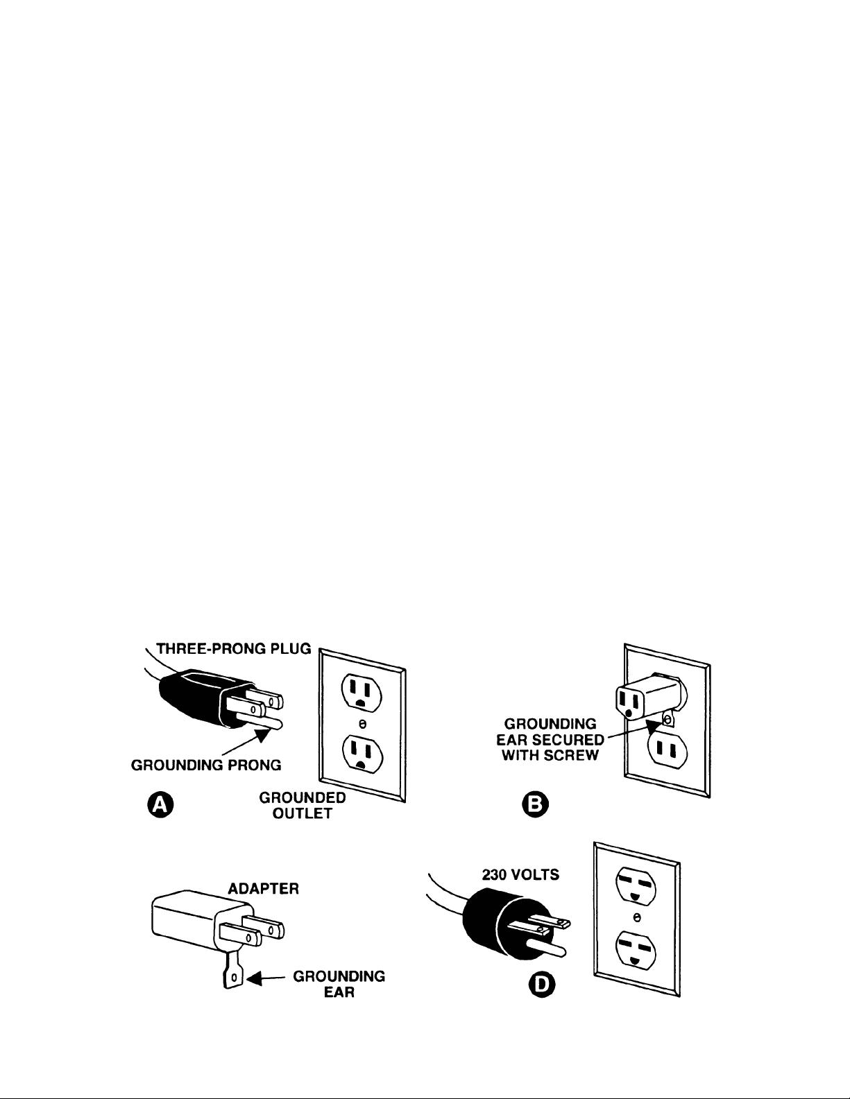
115 Volt Operation
As received from t he factory, your lathe is ready to run at 115 volt operati on. This lathe is int ended for
use on a circuit that has an outlet and a plug that looks like the one illustrated in (A). A temporary
adapter, which looks like the adapter as illustrated in (B), may be used to connect this plug to a two-pole
receptacle, as shown in (B) if a properly grounded out let is not available. The temporar y adapter should
only be used until a properl y grounded out let can be installed by a qualif i ed el ectrici an. This adap ter is
not applicable in Canada. The green col or ed rigid ear, lug, or tab, extending from the adapter, must be
connected to a perm anent ground such as a properly grounded outlet box, as shown in (B).
Page 6

6
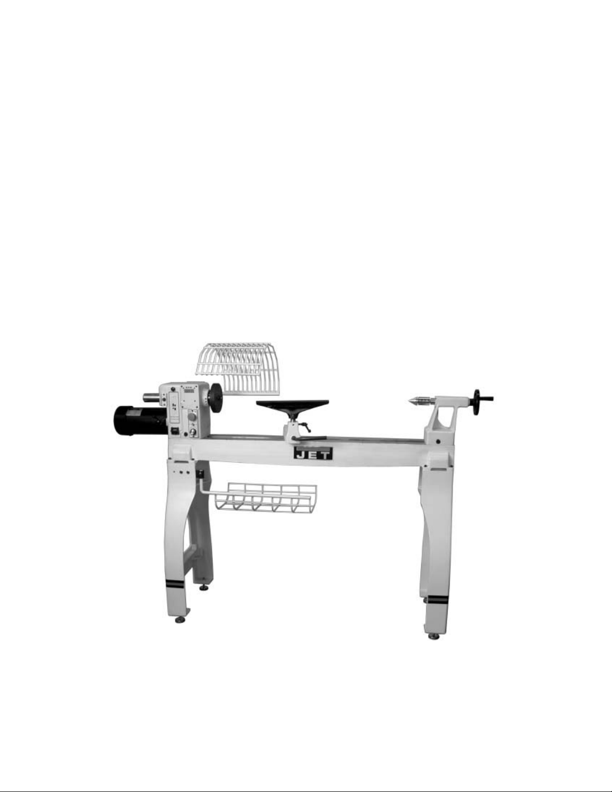
Introduction
The JET JWL-1642EVS lathe you have purchased is a high quality tool that will give you years of superior
service. You will get maximum performance and enj oy m ent from y our new lathe if you would take a few
moments now to review the entir e m anual before beginning assembl y and oper ation.
The JET JWL-1642EVS, as well as al l JET products, is backed by a nationwide network of authorized
distribut ors and/or servi ce centers. Please contact your nearest distri butor should you require parts or
service. Parts are also available direc tly from JET by calling 1-800-274-6848.
Table of Conte nts
Warranty....................................................................................................................... ...........................2
Warnings..............................................................................................................................................3-4
Grounding Instructions.............................................................................................................................5
115V Operation........................................................................................................................................5
Introduction..............................................................................................................................................6
Table of Contents.....................................................................................................................................6
Specifications..........................................................................................................................................7
Contents of the Shipping Container..........................................................................................................8
Unpacking and Cleanup...........................................................................................................................8
Assembly............................................................................................................................................8-10
Stand Shelf..............................................................................................................................................9
Tool Basket ..............................................................................................................................................9
Guard....................................................................................................................................................10
Controls and Feat ur es ...................................................................................................................... 10-11
Speed Change.......................................................................................................................................12
Lathe Tools............................................................................................................................................12
Mounting Workpiece Between Centers...................................................................................................13
Stock Selection......................................................................................................................................14
Roughing Out ........................................................................................................................................14
Coves, “V” Cuts, Parting and B eads....................................................................................................... 15
Sanding & Finishi ng...............................................................................................................................16
Face Plate or Bowl Turning....................................................................................................................16
Mounting Stock............................................................................................................................... .......16
Face Plate or Chuck ..............................................................................................................................17
Wood Selection......................................................................................................................................17
Checks and Cracks................................................................................................................................17
Distortion...............................................................................................................................................17
Tools for Bowl T u rning............................................................................................................................17
To Shape Outside of Bowl......................................................................................................................18
To Shape Interior of Bowl.......................................................................................................................19
Sanding and Finishing ...........................................................................................................................19
Adjusting Clam ping Mechanism.............................................................................................................20
Changing the Belt and B eari ngs.............................................................................................................20
Troubleshooting.....................................................................................................................................21
Part Breakdowns and Part’s List .......................................................................................................22-26
Wiring Diagram......................................................................................................................................27
Page 7
7
Specifications JWL-1642EVS
Stock Number................................................................................................................................ 708359
Over Bed ..............................................................................................................................................16"
Swing Over Tool Rest Base..................................................................................................................12"
Distance Between Centers....................................................................................................................42"
Speeds (RPM).................................................................................................................0-1200 & 0-3200
Spindle Nose.....................................................................................................................1-1/4" x 8 T.P.I.
Drive Spindl e Through Hole.................................................................................................................3/8"
Tailstock Spindle Through Hole............................................................................................................3/8”
Tailstock Spindle Travel....................................................................................................... ...................4”
Tool Rest..............................................................................................................................................14”
Face Plate..............................................................................................................................................6”
Headstock Taper ...............................................................................................................................MT-2
Tailstock Taper..................................................................................................................................MT-2
Spindle Cent er t o Floor ( appr ox .)....................................................................................................44-1/2”
Motor.........................................................................................................................1-1/2 HP, 3Ph, 230V
............................................................................................................................Input Power 115V Only
Net Weight (approx.).....................................................................................................................440 Lbs.
Shipping Weight (approx.).............................................................................................................475 Lbs.
The specifications in this manual are given as general information and are not binding. W M H Tool Group
reserves the right to effect, at any time and without prior notice, changes or alterati ons to parts, fittings,
and accessory equipment deemed necessary for any reason whatsoever.
Page 8
8
WARNING
Read and understand th e entire contents of
this manual before attempting assembly or
operation!
Failure to compl y may cause seri ou s in ju ry!
Contents of the Shipping Containers
1. Lathe
1. Tailstock
1. Headstock
1. Tool Rest Body
1. Tool Basket
1. Guard Assembly
1. Accessory Package
1. Owner’s Manual & Warranty Card
Accessory Package Box
1. Live Center
1. Rod for Live Center
1. Spur Center
1. Index Pin
1. Face Plate
1. Rod for Face Plate
1. Knockout Rod Headstock
1. Tool Rest
4. Adjustable Feet
Tool Basket Bracket Hardware
2. Hex Sckt Cp Screws 5/16”-18 x 1-1/2”
4. Flat Washers 5/16”
2. Set Screws 1/4”-20 x 1/4”
3. Hex Nuts 5/16”
1. Set Screw 5/16”-18 x 5/8”
Unpacking and Clean-Up
1. Remove the shipping container. Do not
discard any shippi ng material until the l athe
is set up and running properly.
2. Remove hex cap bolts from skid bottom and
move the lathe off the ski d and into position.
3. Clean all rust protected surfaces with a
cleaner degreaser. Clean thoroughly under
the headstock, tailstock and tool rest body.
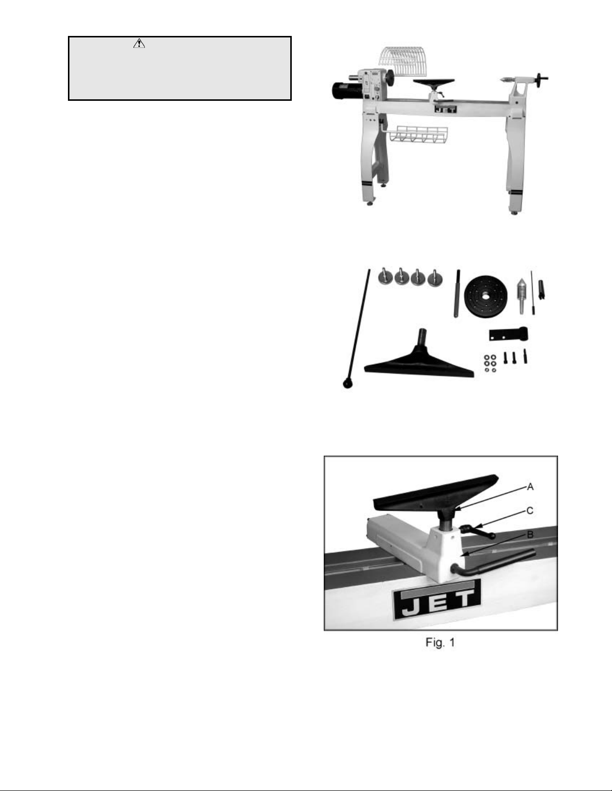
Assembly
1. Secure tool r est (A, Fig. 1) to t ool rest body
(B, Fig. 1) by tight ening handle (C, Fig. 1).
2. Slide the tailstock and tool rest to the
headstock end of the lathe bed. See
“Controls and Features” section of this
manual on how to move the tailstock and
tool rest.
Contents of Accessory Package
Page 9

9
3. Lift the tailstock end of the lathe up far
enough to slide a few pieces of scrap wood
under the leg, see Fi gur e 2.
4. Thread adjustable feet (A, Fig. 2) into stand
leg (B, Fig. 2). There is a flat spot on the
shaft near the f oot that will accommodat e a
wrench. Thread a hex nut (C, Fig. 2) onto
shaft and leave loose for now.
5. Remove the scrap pieces of wood and slide
the tailstock, tool rest and headstock down
to the tailstock end of the lat e bed.
6. Mount the two adjustable feet in the same
manner as above and m ove the headstock,
tool rest and tailstock into their normal
positions.
7. Adjust t he feet so that the lat he rests evenly
on the floor, and tighten the nuts.
Stand Shelf
You can make an ext ra shelf that rests between
the legs if you wish, see Figure 3. It will be
useful for storing lathe accessories, or adding
sand bags for some extra weight. The two
2x4’s should be 55-3/4” long. The plywood
should be ripped into two equal pieces
27-13/16”L x 17”W so that it can be assembled
between the legs. Use screws to attach the
plywood to the 2x4 supports.
Tool Basket
1. Mount the brac ket (D, Fig. 4) to the i nside of
the lathe leg with two 5/16”-18 x 1-1/2” hex
socket cap screws, four 5/16” flat washers
and two 5/16” hex nuts (E, Fig. 4).
2. The two set screws, on the bracket should
be below the bolts and acce ssible from the
backside for adjustment.
3. Place the arm of the tool basket into the
bracket and secure with a 5/16”-18 x 5/8” set
screw and tighten t he 5/16” hex nut (F, Fi g.
4). Line up the notch in the arm with the
set screw so the tool basket can pivot.
4. Adjust t he set screws on the brack et so that
the tool basket swings in a level manner.
Tighten the two hex socket cap screws.
Page 10

10
Guard
1. Attach guard to the brack et by inserting the
rod and lifting up on the plunger ( A, Fig. 5).
2. There are two detents that will hold the
guard in place. One is for turning and the
other is for when you need the guard up and
out of the way.
3. Tighten the bushings (B, Fig. 5) against the
bracket with two set screws (C, Fig. 5).
Controls & Features
1. Headstock Lock Handle: (D, Fig. 6)
Locks head in position. Unlock handle to
position the head al ong lathe bed. Tighten
handle when properly positioned.
2. Headstock Spindle Lo ck: (E, Fig. 6)
Push pin in to keep the spindle from turning.
CAUTION! Never press the headstock
spindle loc k whil e the spindle is turning!
3. Headstock On/Off Bu t ton: (F, Fig.6)
Pull the button out to turn “ON” the lathe.
Push the button in to turn the lathe “OFF”.
4. Headstock RPM Knob: (G, Fig. 6)
Turn knob to desired RPM. There are two
speed ranges offeri ng “speed” (0-3200) and
“torque” (0-1,200).
5. Headstock For/Rev Sw itch: (H, Fig. 6)
Use the toggle switch to change the
direction the spindle turns. Only change
direction when the spindle has stopped.
6. Headstock RPM Readout : (I, Fig. 6)
Displays the spindles RPM, see Figure 7.
7. Headstock Spur Center: (J, Fig. 8)
Used for turni ng between centers. Spindle
taper is MT-2. Remove spur center by
inserting drift rod through the opposite end
of the spindle and knocki ng spur center out.
Page 11

11
8. Headstock Faceplate: (K, Fig. 8)
Used for turning bowls and plates. There
are a number of screw holes for mounting
the workpiece. Thread the faceplate onto
the spindle in a clockwise direction, and
tighten two set screws. Remove the
faceplate by loosening two set screws.
Push in headstock spindl e lock and use the
provided rod in faceplate holes to unthread
the faceplate.
9. Headstock Indexing Hole: (L, Fig. 8)
Thread indexing pin into the indexing hole
making sure that it locates in the spindle
hole. There are 12 holes in the spindle 30°
apart. There are three holes in the
headstock casting that accept the indexing
pin. These holes are 20° apart. The
combination of holes will allow you to mark
your workpiece for evenly spaced features.
CAUTION! Never start the lathe with the
index pin engaged in the spindle!
10. Tool Rest Body Lock Handle: (M, Fig. 9)
Locks the tool rest body in positi on. Unloc k
handle to position the tool rest in any
location along lathe bed. Tighten handle
when properly positioned.
11. Tool Rest Lock Handle: (N, Fig. 9)
Locks the tool rest in position. Unlock the
handle to position tool rest at a specific
angle, or height. Tighten handle when
properly positioned.
12. Tailstock Lock Hand le: (O, Fig. 10)
Locks the tailstock in position. Unlock
handle to position the tool rest in any
location along lathe bed. Tighten handle
when properly positioned.
13. Tailstock Quill Lock Handle: (P, Fig. 10)
Locks the tailstock quill in position. Unlock
handle to positi on the quill. Tighten handl e
when properly positioned.
14. Ta ilstock Quill Handwheel: (Q, Fig. 10)
Turn the handwheel to position the quill.
The tailstock quill lock handl e must be loose
to position quill .
15. Tailstock Live Center: (R, Fig. 10)
Used for turning between centers. Quill
taper is MT-2. Remove live center by
retracting the quill until live center loosens.
Remove, or add different tips to the live
center by inserti ng the provided rod through
the holes in the center’s shaft. Unscrew
the tip and change as needed.
Page 12

12
Speed Change
1. Disconnect the machine from the power
source!
2. Loosen the locking handle (A, Fig. 11).
3. Lift up on the tensioning handle (B, Fig. 11)
to remove tension from the poly v-belt. You
can now position the belt in the desired
speed range. It is pictur ed in the low speed
pulley range. Note: The “High” speed
range (0-3200) provides maximum speed,
where as the “Low” speed range (0-1200)
will provide maximum torque.
4. Lower the tensioning handle so that the
weight of the motor provides the needed
tension and tighten the locking handle.
AC Inverter does not requi re any programming.
It is pre-programmed from the factory. The
buttons and knob on the face of inv erter should
not be changed. Use only controls on the front
of headstock. Refer to Inverter manual.
Lathe Tools
If possible, select only high quality, high speed
steel turning tools with long handles. As one
becomes proficient in turning, a variety of
specialty tools for specific applications can be
acquired. The following tools provide the
basics for most woodturning pr ojects. See your
JET distributor for a wide variety of JET
woodturning tools.
Roughing Gouge - used for rapidly cut raw
wood into round stock , see Figure 12.
Deep Fluted Bowl Gouge - used for turning
bowls and plates, see Figure 12.
Spindl e Gouge - used for tur ning beads, coves
and other details, see F igure 12.
Spear - fine scraping and delicate operations,
such as the forming of beads, parallel grooves
and shallow vees, etc , see Figure 12.
Skew - used to make vees, beads, etc., see
Figure 12.
Square Scraper - used for diameter scraping
and featureless scraping, etc, see Figure 12.
Large Domed Scraper - used to reduc e ridges
on the interior of bowls, round edges of bowls,
etc, see Figure 12.
Parting Tool - used to cut directly into the
material, or to make a cut off. Also used for
scraping and to set di am eters, see Figure 12.
For safety and best performance, keep tools
sharp. If a tool stops cutting, or requires
excessiv e pressure to make a cut, it needs to be
sharpened. A number of brand name
sharpening jigs and fixtures are available,
however, a woodturner should l earn to sharpen
tools freehand.
Page 13

13
Mounting Workpiece Between Centers
Spindle turni ng takes place between the cent ers
of the lathe. It requires a spur center in the
headstock and a liv e center in the tailstock.
1. W ith a ruler locate and mark the center on
each end by going corner to corner, see
Figure 13. Accuracy is not critical on full
rounds but extremely important on stock
where square sections are t o remain. Put a
dimple in each end of the stock wit h an awl,
or nail.
2. Extrem ely hard woods may requi re kerfs cut
into the spur drive end of stock, see Figure
13. You may need to dr ive the spur center
into the stock with a wood mallet. Note:
Never drive stock onto spur while it is
mounted in the lathe spindle.
3. Install workpiece by inserting the attached
spur center into the spindle taper on the
headstock.
4. Bring tailstock into position, lock it to the
bed, and advance quill with the handwheel
in order to seat the live center into the
workpiece. Lock the quill in place. Make
sure the live center point is centered on your
mark.
5. Move tool rest into position. It should be
parallel to workpiece, approximately at the
centerline, and approximately 1/8" from the
closest part of the workpiece. Lock tool rest
body and tool rest in plac e.
6. Rotate workpiece by hand to check for
proper clearance from tool rest. Note:
You may want to trim off the corners of a
square workpiece to make turning a little
easier, see Figur e 14.
7. Start lathe at lowest
the appropriate RPM for the size of stock,
see Figure 7 page 10.
The position of the tool rest can be v aried t o suit
the work and operator. After you become
experienced with setting the tool rest changing
the position will become second nature for the
workpiece and comfort of the user.
speed and bring it up to
Page 14

14
Stock Sele ct ion
Stock for spindles should be straight grained
and free of checks, cracks, knots and other
defects. It should be cut 1/ 8" to 1/4" lar ger than
the finished di ameter and may require additional
length to rem ove ends if requir ed. Larger stock
should have the cor ners removed to produc e an
octagon making t he piece easier t o rough down
to a cylinder, see Figur e 14.
Roughing Out
1. Use a large roughing gouge and begin
cutting about 2” fr om the tailstock end of the
workpiece. Place the tool on tool rest with
heel of the tool on surfac e to be cut.
2. Slowly and gently raise tool handle until
cutting edge comes into contact with the
workpiece. Work to the right towards the
end of the workpiece. You never want to
start at the end of a workpi ec e.
3. Now continue to work the rest of the
workpiece. Roll the flute (hollowed-out
portion) of the tool in the dir ection of the cut,
see Figure 15. Make long sweeping cuts in
a continuous motion to rough the piece
down to a cylinder. Keep as much of the
bevel of tool as possible in contact with
workpiece to ensure control and avoid
catches. Note: Always cut down-hill, or
from large diameter to small diameter.
Al ways wo rk toward the end of a workpiece,
never start cut ting at the end.
4. Once the workpiece is roughed down to a
cylinder, smooth it with a large skew. Pl ace
the cutting point near the center of the chisel
and high on the workpiece, see Figure 16.
Touching one of the points of the skew to
the spinning workpiece may cause a catch
and ruin the workpi ec e.
5. Add details to the workpiece with skew,
spindle gouge, etc.
Page 15

15
Coves
1. Use a spindle gouge. With the flute of t he
tool at 90 degrees to workpiece, touch the
center of the cutting edge to the workpiece
and roll in towards the bottom of the cove.
Stop at the bottom; attempting to go up the
opposite side m ay cause the t ool to catch.
2. Move tool over the desired width of cove.
3. W ith the flute facing the opposite direction,
repeat step 1 for ot her si de of cov e. Stop at
bottom of cut, see Figure 18.
“V” Cuts
1. Use the long point of the skew. Note: Do
not press the long poi nt of the skew directl y
into the workpi ece to creat e the "V"; t his will
result in a burned, or burnished "V" with
fibers being r olled up at both sides.
2. Li ghtly m ark the center of the "V" wit h the tip
of the skew.
3. Move the point of skew to the right half of
the desired width of y our cut , see Figure 19.
4. With the bevel parallel to the right si de of the
cut, raise the handl e and push the tool in to
the desired depth.
5. Repeat from the left side. The two cuts
should meet at the bottom and leave a clean
"V" cut.
6. Additional c uts m ay be taken to add to either
the depth or width of t he cut.
Parting
1. Place parting tool on tool rest and raise the
handle until it starts to cut and continue to
cut to the desired dept h.
2. If the cut is deep a clearance cut should be
made along side the first c ut to prevent the
tool tip from burning.
Beads
1. Place parting tool on tool rest and move tool
forward to make t he f ull bev el of tool come
in contact with workpiece. Gently raise
handle to make cut to appropr iate depth.
2. Repeat for other side of t he bead.
3. Using a small skew or spindle gouge, star t in
the center between the two cuts and cut
down each side to form the bead. Roll the
tool in direction of cut.
Page 16

16
Sanding & Finishing
Leaving clean cuts will reduce the amount of
sanding required. Adjust lathe to a finishing
speed, and begin with fine sandpaper (120 grit
or finer). Coarser sandpaper will leave deep
scratches that are difficult to remove, and dull
crisp detail s. Fold t he sandpaper int o a pad; do
not wrap sandpaper around your fingers or the
workpiece.
To apply a fini sh, the workpiece can be l eft
on the lathe. Tur n off lathe and use a brush, or
cloth to apply the finish. Remove excess finish
before restarting lathe. Allow to dry and sand
again with 320, or 400 grit sandpaper. Apply
additional coats of finish and buff.
Face Plate & Bowl Turning
Face plate turning is normally done on the
inboard side of the headstock ov er the bed, see
Figure 20. You must move headstock to the
end of the lathe bed for larger workpieces.
Mounting Stock
Use of a face plat e i s the m ost c ommon m ethod
for holding a block of wood for turning bowls,
and plates, see Fi gur e 21.
1. Select stock at least 1/8" to 1/4" larger than
the dimension on the desired finished
workpiece.
2. True one surface of workpiece for mounting
against the face plate. It is best to leave
extra stock against the face plate that can
be cut off when the workpiece is finished.
3. Using t he f ace plat e as a templat e, mark t he
location of the mounti ng holes, and drill pil ot
holes of the appropriate size. If the
mounting screws on the face plat e interf ere
with the workpiece, a waste block can be
mounted to the face plate and then the
waste block mounted to the workpiece by
gluing or screwing, see Figure 21.
4. Both waste block and workpiece should
have good flat surfaces.
5. Push in the spindle lock and thread face
plate and workpiece onto spindle. Tighten
set screws in face plate when secure.
Page 17

17
Face Plate or Chuck
While facepl ates are the sim plest, most reliabl e
method of holding a block of wood for turning,
chucks can also be used. A chuck is not a
requirement but is handy when working on more
than one piece at a time. Rather t han removi ng
screws, you simply open the chuc k and change
workpieces. The most popular ones are four
jaw scroll chucks with a variety of jaws to
accomodate different size tenons. Most also
come with a screw chuck as well.
Wood Selection
Firewood is the cheape st, most widely av ailable
stock to use while learning to turn bowls.
Develop skill with each tool before attempti ng to
make a finished piece. It is best to start with
dry wood, without worrying about drying or
distortion. Once turning becomes comfortable,
try green wood which cuts very easily. As the
turner gains experience, he or she will find
extraordinary grain and figure in the form of
burls, crot c hes and bark inc lusions.
Checks & Cracks
Green wood will check and crack. For best
results, leav e logs in as long lengths as you can
handle. As the material starts to dry, surface
cracks will develop on the ends of the log. Cut
off two to three inches and you should f ind good,
sound wood. Also cut the log i n half along the
pith to avoid having it in the finished piece.
Most checks radiat e from the pith. As you turn
bowls from green wood, make sure you maintain
a consistent wall t hickness throughout the pi ece.
Leaving a piece thick in some areas and thin in
others will cause the wood to dry unevenly and
promote checks and crac k s.
Distortion
Distortion is a problem associated with turning
green wood. I t will vary from one ty pe of wood
to the next. Typicall y, fruitwoods tend to di stort
more than others. It also varies with the tim e of
year the tree was cut and how the logs are
stored.
Tools for Bowl Turning
The deep fluted bowl gouge is the most
essential and versatile tool for most bowl and
faceplate style turning. The bowl gouge is
heavier and easier t o control t han other types of
gouges. It also allows removal of wood much
faster and wit h less vibration t han other gouges.
Most average sized bowl work can be
accomplished with a 3/ 8" or 1/2" bowl gouge. A
1/4" bowl gouge is best suited f or smaller bowls
and light fi nishing c uts. Larger 3/4" and 1" bowl
gouges are only used for extremely large pieces.
Large domed scraper s can also be u sed to help
clean up the interi or surfaces of bowls. A light
touch with the scraper sli ghtly tilt ed will elimi nat e
some of the ridges left by a bowl gouge.
Page 18

18
To Shape Outside of Bowl
1. Odd shaped burls, crotches and other
irregular shaped blanks require special
preparation before mounting in a chuck, or
onto a faceplate. Remove the bark, if there
is any, from what appears to be the c enter of
the top of workpiece.
2. Driv e spur center into the top of workpiece
with a wood mallet.
3. Slip spur center into headstock taper and
bring the tailstock, with a live center into
position. Loc k tailst ock to bed and adv ance
spindle in order to seat the cup center into
workpiece, see Figure 22. Tighten quill
lock.
4. Position tool support just below the
centerline and about 1/4" from the
workpiece. Note: For larger outboard
turning, an optional outboard turning stand is
used to place the tool support , see your JE T
distributor.
5. Turn workpiece by hand to ensure proper
clearance.
6. St art lat he at lowest speed and bri ng i t up t o
the maximum safe speed for the size of
work to be turned, see Figure 7 on page 10.
If the machine starts to vibrate, lower the
speed until vibr ation stops.
7. Rough out the outside of the bowl with the
1/2" deep fluted bowl gouge, holding the tool
firmly against your hip. For best control,
use your whole body to move the gouge
through the workpiec e.
8. As the bowl takes shape, work on the
bottom (tailstock end) to accomodate
attaching a face pl ate, see Figure 22.
9. Tur n a short t enon (about 1/ 8" l ong) t he size
of the hole in the faceplate, see Figure 22.
This will all ow centeri ng the workpi ece when
the faceplate is attached. Note: If you
plan to use a chuck, turn a tenon of
appropriate length and diameter to fit your
chuck.
10. S top the lathe, remove workpiece and attach
face plate, or chuck .
11. Finish turning the outside of bowl with 1/2"
or 3/8" bowl gouge. Leave additional
material at base of bowl for support while
turning interior. T his will be removed later.
Page 19
19
To Shape In terio r of Bo wl
1. Stop lathe and move tailstock away.
Remove center from tailstock to prevent
bumping it with el bow.
2. Adjust tool support in front of the bowl j ust
below centerli ne, at a right angle to t he lathe
bed.
3. Rotate workpiece by hand to check
clearance.
4. Face off top of bowl by making a light
shearing cut acros s the workpiece, from rim
to center.
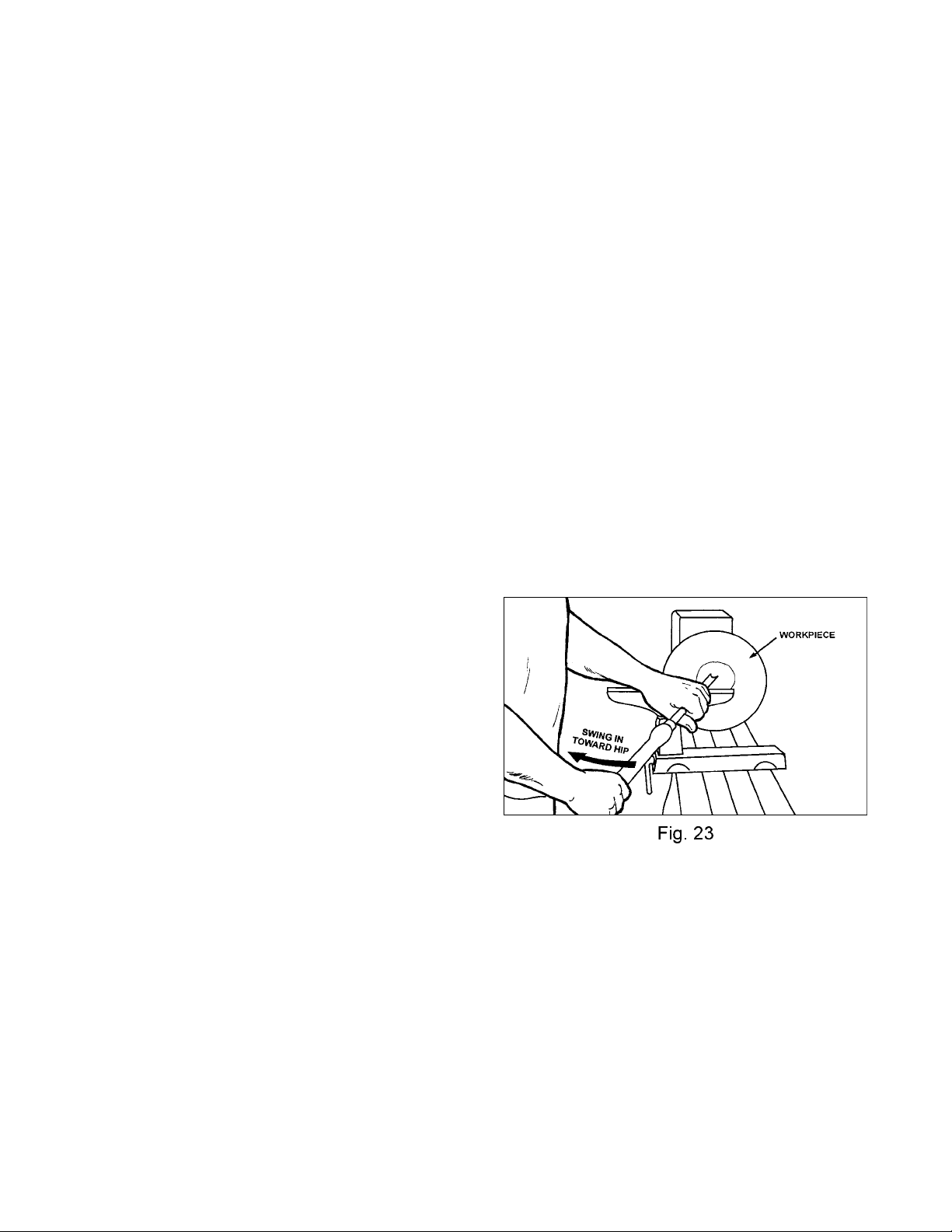
5. Place 1/2" bowl gouge on tool rest at center
of the workpiece with the flute facing t op of
bowl. The tool handle should be level and
pointed toward four o' cl oc k , see Figure 23.
6. Use left hand to control cutting edge of
gouge, while right hand swings tool handle
around toward your body, see Figure 23.
The flute should start out facing top of
workpiece, and rotate upward as it moves
deeper into the bowl to maintain a clean
even curve. As tool goes deeper into bowl,
progressiv ely work out t oward rim . It may be
necessary to t urn the tool r est into the work
piece as you get deeper into the bowl.
Note: Try to make one, very light
continuous movement from the rim to the
bottom of the bowl to ensure a clean,
sweeping curve through the workpiece.
Should there be a few small ridges left, a
light cut with a large domed scraper can
even out the surface.
7. Develop wall thickness at the rim and
maintain it as you work deeper into t he bowl.
When the interior is finished, move tool
support to exterior to re-define bottom of
bowl. General rule of thumb: the base
should be approximately 1/3 the overall
diameter of t he bowl.
8. Work the tight area around faceplate or
chuck with 1/4" bowl gouge.
Sanding and Finsihing
1. Remove the toolrest and adjust lathe speed
to the appropriate finishing speed. High
speed can build friction while sanding and
cause heat check in some woods.
2. Begin with fine sandpaper 120 grit and
progress through each grit, using only light
pressure. Coarser sandpaper tends to
leave deep scratches that are hard to
eliminate. Use power-sanding techniques
to avoid concentric sanding marks around
your finished pi ece. Avoi d rounding over the
rim and foot with sandpaper. Try to keep
details cri sp. Finish sanding with 220 grit .
3. Remove sanding dust with tack rags, or
compressed air and, with lathe turned off,
apply first coat of finish. Let stand for
several minutes, wipe off excess. Allow to
dry before sanding again with 320 or 400 grit
sandpaper.
4. Turn lathe back on and make a separation
cut through the base. Stop at about 3" and
use a small fine tooth saw to separate the
bowl from the waste.
5. Appl y additi onal finish coats and al low to dry
before buffing.
Page 20

20
Adjusting Clamping Mechanism
The clamps are pre- set at the fac tory and should
not need any adjustment. However, if
adjustment is needed remove the stud (A, Fig.
24). Loosen the locking handle and slide the
headstock, tailstock or tool rest to the edge of
the bed and slightl y turn the hex nut (B, Fig. 24).
Slide back into position and test the handle to
make sure it securely locks.
Changing the Belt and Bearings
Changing belt and bearings can be a difficult
task, and should be performed by a JET
authorized repair station. Remove headstock
and take into a repair station for servicing.
1. Disconnect the machine from the power
source!
2. Loosen the locking handl e (C, Fig. 25), and
lift up on the tensioni ng handle (D, Fig. 25)
to remove tension from the poly v-belt.
3. Open door (E, Fig. 25) , and remove the bel t
(F, Fig. 25) from the lower pul ley.
4. Loosen t wo set scre ws in the handwheel ( G,
Fig. 25) and remov e.
5. Loosen socket head cap screw enough to
unthread the cl amping nut (H, Fig. 25).
6. Loosen two set screws in the right hand
pulley (I, Fi g. 25).
7. Loosen set screw in the coll ar (J, Fi g. 26)
8. Use a wood dowel, or aluminum stock to
knock spindle t owards the tai lstock. Use a
material that is softer than the spindle so
you do not mushroom end of spindle. Go
only far enough to remove belt from spindle,
see Figure 26.
9. Now you can replace the belt or bearings.
There are two bearings #5, and 10 that can
be seen in “Headstock Assem bly,” page 24.
10. To reassemble reverse the procedure.
Note: When reinstalling clamping nut
thread it on to the spindle until its snug.
Then back off slight ly and tighten t he socket
head cap screw.
Page 21

21
to workpiece and headstock.
Troubleshooting
Problem Possible Cause Solution
Excessive Vibr ation.
Motor or Spindle St all s or W ill not
Start
Motor fails to develop full power.
Tools tend to grab or dig in.
Tailstock Moves When Applying
Pressure
Digital readout does not work
1. Workpiece warped, out of
round, has maj or flaw, or was
improperly pr epar ed for
turning
2. Worn spindle bearings
3. Worn belt
4. Motor mount bolt or handl e
loose
5. Lathe on uneven surface
1. Excessive cut
2. Worn motor
3. Broken belt
4. Worn spindle bearings
5. Improper cooling on m otor
1. Power line overloaded
2. Undersize wires in supply
system
3. Low voltage
4. Worn motor
1. Dull tools
2. Tool support set too low
3. Tool support set too f ar from
workpiece
4. Improper tool bei ng used
1. Excessive pressure being
applied by tail stoc k. Note:
The screw action of the
tailstock is capable of
applying excessive pressure
Apply only suffi ci ent force by
tailstock t o hol d workpiece
securely in place.
Exc essive pressure can
cause damage to machine.
2. Lathe bed and tailstock
mating surfac es are greasy
or oily.
1. Digital readout sensor out of
position
1. Correct problem by planing,
bandsawing, or scrap
workpiece all t ogether
2. Replace bearings
3. Replace belt
4. Tighten bolt or handl e
5. Shim lathe bed, or adjust feet
on stand
1. Reduce cut depth
2. Replace motor
3. Replace belt
4. Replace bearings
5. Clean sawdust from motor
fan
1. Correct overload condition
2. Increase supply wire siz e
3. Request voltage check from
power company and c orrect
low voltage condition
4. Replace motor
1. Sharpen tools
2. Reposition tool support
height
3. Reposition tool support
closer to workpiec e
4. Use correct tool for operation
1. Slide tailstock down to the
right side of t he lathe against
the stop. Move headstock
into positi on and apply
pressure to workpiece wit h
tailstock.
2. Remove and clean surfaces
with a cleaner degreaser
1. Open the belt access and
position the sensor so that it
reads the bolts
Page 22
22
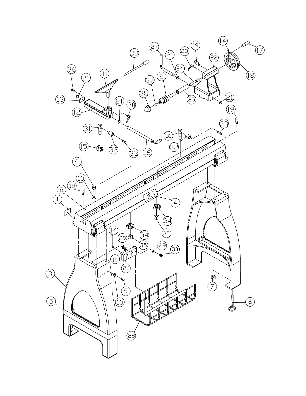
Stand and Bed Assembly
Page 23

23
Parts List for the JWL-1642EVS Woodworking Lathe
Stand and Bed Assembly
Index Part
No. No. Description Size Qty.
1..........JWL1642-201............... I.D. Label............................................... ...............................................1
2..........JWL1642-202............... Live Center............................................MT2 ........................................1
3..........JWL1642-203............... Stand..................................................... ...............................................2
4..........JWL1442-219............... JET Label.............................................. ...............................................1
5..........JWL1642-205............... JET Strip e .............................................. ...............................................1
6..........JWL1642-206............... Adjustable Foot......................................3/8” .........................................4
7..........TS-0561031.................Hex Nut.................................................3/8” .........................................4
8..........JWL1442-201............... Bed........................................................ ...............................................1
9..........TS-0208081.................Hex Socket Cap Screw..........................5/16”-18 x 1-1/2”....................10
10........TS-0680032................. Flat Washer...........................................5/16”.....................................12
11........JWL1642-211............... Tool Rest............................................... ...............................................1
12........JWL1442-207............... Tool Rest Base...................................... ...............................................1
13........JWL1442-208............... End Cover ............................................. ...............................................1
14........TS-0267021................. Set Screw..............................................1/4”-20 x 1/4”...........................6
15........JWL1442-129............... Support Bracket..................................... ...............................................1
16........JWL1442-210............... Tool Support Rod................................... ...............................................1
17........JWL1442-211............... Handle................................................... ...............................................1
18........JWL1442-212............... Handwheel ............................................ ...............................................1
19........JWL1442-202............... Stud....................................................... ...............................................3
20........JWL1442-206............... Tool Support Handle..............................3/8” .........................................1
21........JWL1442-124............... C-Ring...................................................S19.........................................4
22........JWL1642-222............... Tailstock................................................ ...............................................1
23........JWL1442-218............... Tailsto ck Qu i l l Handle............................5/16” .......................................1
24........JWL1442-214............... Lead Screw ........................................... ...............................................1
25........JWL1442-215............... Quill....................................................... ...............................................1
26........JWL1642-226............... Bracket.................................................. ...............................................1
27........JWL1442-217............... Tailstock Rod......................................... ...............................................1
28........JWL1642-228............... Storage Basket...................................... ...............................................1
29........TS-0570021................. Hex Nut.................................................5/16”.......................................3
30........TS-0270061................. Set Screw..............................................5/16”-18 x 5/8”.........................1
31........JWL1442-128............... Clamp Bolt ............................................. ...............................................2
32........JWL1442-127............... Bushing ................................................. ...............................................2
33........JWL1442-126............... Key........................................................5 x 5 x 30................................2
34........JWL1442-154............... Clamp.................................................... ...............................................2
35........TS-0561081................. Hex Nut.................................................3/4”-10....................................2
36........TS-0206011................. Hex Socket Cap Sc re w..........................#10- 24 x 3/8”...........................4
37........JWL1642-237............... Tip......................................................... ...............................................1
38........JWL1642-238............... Cap ....................................................... ...............................................1
39........JWL1642-239............... Knockout Rod........................................ ...............................................1
............ JWL1642-TCA..............Tailstock Complete Assembly (not shown).............................................1
............ JWL1642-TRCA........... Tool Rest Complete Assembly (not shown)............................................1
Page 24
24
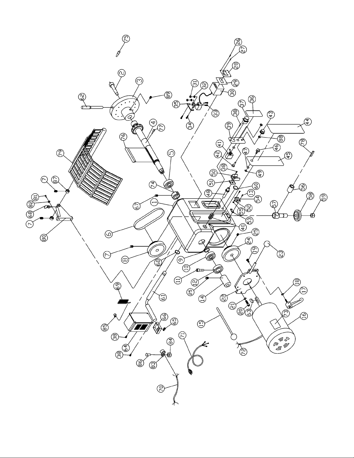
Headstock Assembly
Page 25

25
Parts List for the JWL-1642EVS Woodworking Lathe
Headstock Assembly
Index Part
No. No. Description Size Qty.
1..........JWL1642-101............... Headstock ............................................. ...............................................1
2..........JWL1642-102............... Spur Center...........................................MT2 ........................................1
3..........JWL1642-103............... Face Plate.............................................6” ............................................1
4..........JWL1642-104............... Spindle.................................................. ...............................................1
5..........BB-6207ZZ...................Ball Bearing...........................................6207ZZ ...................................1
6..........VB-180J....................... Poly-V Belt.............................................180J........................................1
7..........TS-0270011.................Set Screw..............................................5/16”-18 x 1/4”.........................4
8..........JWL1642-108............... Spindle P u l ley........................................ ...............................................1
9..........JWL1642-109............... Wave Washe r........................................ø49.........................................1
10........BB-6205ZZ................... Ball Bearing...........................................6205ZZ ...................................1
11........TS-0207041................. Hex Socket Cap Sc re w..........................1/4”-20 x 3/4”...........................1
12........JWL1642-112............... Lock Nut................................................M22.........................................1
13........TS-0207021................. Hex Socket Cap Sc re w..........................1/4”-20 x 5/8”...........................4
14........JWL1642-114............... Hand Wheel........................................... ...............................................1
15........JWL1442-164............... Knockout Rod........................................ ...............................................1
16........JWL1642-116............... Motor.....................................................1.5 HP.....................................1
............ JWL1642-MFC............. Motor Fan Cover (not shown)................. ...............................................1
............ JWL1642-MF ...............Motor Fan (not shown) ........................... ...............................................1
17........JWL1642-117............... Handle...................................................3/8”-16 x 1”..............................1
18........TS-0680042................. Flat Washer...........................................3/8”.........................................1
19........TS-228820...................Flat Head Screw....................................M8 x 20...................................4
20........TS-0209051................. Hex Socket Cap Sc re w..........................3/8”-16 x 1”..............................1
21........TS-0720091................. Lock Washe r ..........................................3/8”.........................................1
22........JWL1642-122............... Motor Assembly Plate............................ ...............................................1
23........JWL1642-123............... Knob...................................................... ...............................................1
24........JWL1642-124............... Motor Pulley........................................... ...............................................1
25........TS-0267021................. Set Screw..............................................1/4”-20 x 1/4”...........................4
26........TS-0206031................. Socket Head Cap Screw ........................#10- 24 x 5/8”...........................4
27........JWL1642-127............... Tap Screw............................................. M3x10.....................................4
28........JWL1642-128............... DRO Cover............................................ ...............................................1
29........JWL1642-129............... Plate...................................................... ...............................................1
30........JWL1642-130............... Digital Readout...................................... ...............................................1
31........TS-1540011................. Nut ........................................................M3 ..........................................2
32........TS-236103...................Lock Was h e r..........................................M3 ..........................................2
33........TS-2283202................. Round Head Screw................................M3 x 20...................................2
34........JWL1642-134............... Tapping Screw.......................................1/4” x 1/2”................................2
35........JWL1642-135............... Bracket.................................................. ...............................................1
36........JWL1642-136............... Label Control Panel ............................... ...............................................1
37........JWL1642-137............... Push /Pu ll Switch.................................... ...............................................1
38........TS-0206011................. Socket Head Cap Screw ........................#10- 24 x 3/8”...........................8
39........JWL1642-139............... Panel Cover........................................... ...............................................1
40........JWL1442-116............... Spring.................................................... ...............................................1
41........JWL1642-141............... Fwd/Rev Switch..................................... ...............................................1
42........JWL1642-142............... Variable Speed Control.......................... ...............................................1
43........JWL1642-143............... Variable Speed Knob............................. ...............................................1
44........JWL1642-144............... Speed Label .......................................... ...............................................1
45........JWL1642-145............... Belt Door ............................................... ...............................................1
46........JWL1642-146............... Knob...................................................... ...............................................1
47........JWL1642-147............... O-Ring................................................... ...............................................1
48........JWL1442-122............... Spindle Lock Pin.................................... ...............................................1
Page 26

26
Index Part
No. No. Description Size Qty.
49........JWL1642-149............... Retaining Wash er.................................. ...............................................1
50........JWL1442-121............... Bracket.................................................. ...............................................1
51........JWL1442-153............... Plate...................................................... ...............................................1
52........TS-0720041................. Lock Washe r ..........................................#8 ...........................................2
53........JWL1642-155............... Pad........................................................ ...............................................1
54........JWL1642-154............... Door Hinge............................................ ...............................................1
55........TS-056006...................Hex Nut .................................................#8-32 ......................................2
56........JWL1442-127............... Bushing ................................................. ...............................................1
57........JWL1442-128............... Clamp Bolt ............................................. ...............................................1
58........JWL1442-154............... Clamp.................................................... ...............................................1
59........TS-0561081................. Hex Nut.................................................3/4”-10....................................1
60........JWL1442-124............... C-Ring...................................................S19.........................................2
61........JWL1642-161............... Lever..................................................... ...............................................1
62........JWL1642-162............... Handle................................................... ...............................................1
63........JWL1642-163............... Key........................................................5 x 5 x 40................................1
64........JWL1642-164............... Inverter.................................................. ...............................................1
65........JWL1642-165............... Strain Relief........................................... ...............................................3
66........JWL1642-166............... Bracket.................................................. ...............................................1
67........TS-0270011................. Set Screw..............................................5/16”-18 x 1/4”.........................1
68........JWL1642-168............... Plunger.................................................. ...............................................1
69........JWL1642-169............... Braking Resistor.................................... ...............................................1
70........JWL1642-170............... Signal Cord............................................ ...............................................1
71........JWL1642-171............... Power Cord ........................................... ...............................................1
72........JWL1642-172............... Motor Cord ............................................ ...............................................1
73........JWL1642-173............... Motor Label ........................................... ...............................................1
74........JWL1642-174............... Collar..................................................... ...............................................1
75........JWL1442-169............... Index Pin ............................................... ...............................................1
76........JWL1642-176............... Key........................................................8 x 8 x 90................................1
77........TS-0051021................. Hex Head Bolt .......................................5/16”-18 x 5/8”.........................4
78........JWL1442-126............... Key........................................................5 x 5 x 30................................1
79........JWL1642-179............... Guard.................................................... ...............................................1
80........JWL1642-180............... Guard Bracket....................................... ...............................................1
81........TS-0209071................. Hex Socket Cap Sc re w ........................3/8”-16 x 1-1/2”........................2
82........TS-0720091................. Lock Washe r ..........................................3/8”.........................................2
83........JWL1642-183............... Cable Clamp.......................................... ...............................................1
84........TS-056007...................Hex Nut .................................................#10..........................................1
85........JWL1642-185............... Cable Clamp.......................................... ...............................................1
86........TS-0206021................. Hex Socket Cap Sc re w..........................#10- 24 x 1/2”...........................1
87........JWL1642-187............... Collar..................................................... ...............................................2
88........JWL1642-188............... Hex Nut ................................................. ...............................................2
89........TS-1524031................. Set Screw..............................................M8x12 .....................................2
Page 27

27
Wiring Diagram
 Loading...