

Page 1
This .pdf document is bookmarked
Operating Instructions and Parts Manual
14”x 40” Woodturning Lathe
Model JWL-1440VS
JET
427 New Sanford Road
LaVergne, Tennessee 37086 Part No. M-719400
Ph.: 800-274-6848 Revision C 11/2014
www.jettools.com Copyright © 2014 JET
Shown with optional20-inch extension bed (#719401)
Page 2

1.0 Warranty and Service
JET warrants every product it sells against manufacturers’ defects. If one of our tools needs service or repair, please
contact Technical Service by calling 1-800-274-6846, 8AM to 5PM CST, Monday through Friday.
Warranty Period
The general warranty lasts for the time period specified in the literature included with your product or on the official
JET branded website.
• JET products carry a limited warranty which varies in duration based upon the product. (See chart below)
• Accessories carry a limited warranty of one year from the date of receipt.
• Consumable items are defined as expendable parts or accessories expected to become inoperable within a
reasonable amount of use and are covered by a 90 day limited warranty against manufacturer’s defects.
Who is Covered
This warranty covers only the initial purchaser of the product from the date of delivery.
What is Co vered
This warranty covers any defects in workmanship or materials subject to the limitations stated below. This warranty
does not cover failures due directly or indirectly to misuse, abuse, negligence or accidents, normal wear-and-tear,
improper repair, alterations or lack of maintenance. JET woodworking machinery is designed to be used with Wood.
Use of thes e machines i n the pr ocess i ng of m etal, plastics, or other m aterials m ay void the warranty. The except ions
are acrylics and other natural items that are made specifically for wood turning.
Warranty Limitations
Woodworking products with a Five Year Warranty that are used for commercial or industrial purposes default to a
Two Year Warranty. Please contact Technical Service at 1-800-274-6846 for further clarification.
How to Get Technical Support
Please contact Technical Service by calling 1-800-274-6846. Please note that you will be asked to pro vi d e pr o of
of initia l p u rch a s e whe n calling. If a product requires further inspection, the Technical Service representative will
explain and assist with any additional action needed. JET has Authorized Service Centers located throughout the
United States. For the name of an Authorized Service Center in your area call 1-800-274-6846 or use the Service
Center Locator on the JET website.
More Information
JET is constantly adding new products. For complete, up-to-date product information, check with your local distributor
or visit the JET website.
How State Law Appli es
This warranty gives you specific legal rights, subject to applicable state law.
Limitations on This Warranty
JET LIMITS ALL IMPLIED WARRANTIES TO THE PERIOD OF THE LIMITED WARRANTY FOR EACH PRODUCT.
EXCEPT AS STATED HEREIN, ANY IMPLIED WARRANTI ES OF MERCHANTABILITY AND FITNESS FOR A
PARTICULAR PURPOSE ARE EXCLUDED. SOME STATES DO NOT ALLOW LIMITATIONS ON HOW LONG AN
IMPLIED WARRANTY LASTS, SO THE ABOVE LIMITATION MAY NOT APPLY TO YOU.
JET SHALL IN NO EVENT BE LIABLE FOR DEATH, INJURIES TO PERSONS OR PROPERTY, OR FOR
INCIDENTAL, CONTINGENT, SPECIAL, OR CONSEQUENTIAL DAMAGES ARISING FROM THE USE OF OUR
PRODUCTS. SOME STATES DO NOT ALLOW THE EXCLUSION OR LIMITATION OF INCIDENTAL OR
CONSEQUENTIAL DAMAGES, SO THE ABOVE LIMITATION OR EXCLUSION MAY NOT APPLY TO YOU.
JET sells through distributors only. The specifications listed in JET printed materials and on official JET website are
given as general information and are not binding. JET reserves the right to effect at any time, without prior notice,
those alterations to parts, fittings, and accessory equipment which they may deem necessary for any reason
whatsoever. JET
Product Listing with Warranty Period
90 Days – Parts; Consumable items; Light-Duty Air Tools
1 Year – Motors; Machine Accessories; Heavy-Duty Air Tools; Pro-Duty Air Tools
2 Year – Metalworking Machinery; Electric Hoists, Electric Hoist Accessories; Woodworking Machinery used
for industrial or commercial purposes
5 Year – Woodworking Machinery
Limited Lifetime – JET Parallel clamps; VOLT Series Electric Hoists; Manual Hoists; Manual Hoist
Accessories; Shop Tools; Warehouse & Dock products; Hand Tools
NOTE: JET is a division of JPW Industries, Inc. References in this document to JET also apply to JPW Industries,
Inc., or any of its successors in interest to the JET brand.
®
branded products are not sold in Canada by JPW Industries, Inc.
2
Page 3

2.0 Table of contents
Section Page
1.0 Warranty and Service ..................................................................................................................................... 2
2.0 Table of contents ............................................................................................................................................ 3
3.0 Safety warnings .............................................................................................................................................. 4
4.0 About this manual .......................................................................................................................................... 5
5.0 Specifications ................................................................................................................................................. 6
5.1 JWL-1440VS hole pattern .......................................................................................................................... 7
6.0 Setup and assembly ....................................................................................................................................... 8
6.1 Shipping contents ....................................................................................................................................... 8
6.2 Unpacking and cleanup .............................................................................................................................. 8
6.3 Mounting lathe to bench ............................................................................................................................. 8
6.4 Installing leg set .......................................................................................................................................... 8
6.5 Mounting bed extension (optional accessory) ............................................................................................ 9
6.6 User-made storage shelf ............................................................................................................................ 9
7.0 Electrical connections .................................................................................................................................. 10
7.1 Grounding instructions ................................................................................................... .......................... 10
7.2 Voltage conversion ................................................................................................................................... 10
7.3 Extension cords ........................................................................................................................................ 11
8.0 Adjustments ................................................................................................................................................. 11
8.1 Headstock sliding ..................................................................................................................................... 11
8.2 Headstock rotation ................................................................................................................................... 11
8.3 Tailstock movement ................................................................................................................................. 11
8.4 Cam tightness ............................................................................................................ .............................. 12
8.5 Tool rest ................................................................................................................................................... 12
8.6 Tool rest extension ................................................................................................................................... 12
8.7 Locking handles ....................................................................................................................................... 12
8.8 Spindle indexing ....................................................................................................................................... 12
8.9 Spur cen ter: Installing/removing ............................................................................................................... 13
8.10 Live center: Installing/removing .............................................................................................................. 13
8.11 Spindle lock ............................................................................................................................................ 13
8.12 Face plate: Installing/removing ............................................................................................................... 13
8.13 Checking center alignment ..................................................................................................................... 14
9.0 Operating controls ........................................................................................................................................ 14
10.0 Operation ................................................................................................................................................... 14
10.1 Inspection ............................................................................................................................................... 14
10.2 Turning Tools ........................................................................................................... .............................. 15
10.3 Spindle Turning ...................................................................................................................................... 15
10.4 Stock Selection ....................................................................................................................................... 16
10.5 Cutting Techniques ................................................................................................................................ 17
10.6 Face Plate and Bowl Turning ................................................................................................................. 18
10.7 Bowl Turning Techniques ....................................................................................................................... 19
11.0 Maintenance ............................................................................................................................................... 21
11.1 General procedures ................................................................................................................................ 21
11.2 Pulley lubrication .................................................................................................................................... 21
11.3 Belt and bearings replacement ............................................................................................................... 21
12.0 Optional accessory ..................................................................................................................................... 21
13.0 Troubleshooting the JWL-1440VS Lathe ................................................................................................... 22
14.0 Recommended Lathe Speeds (per diameter of workpiece) ....................................................................... 23
15.0 Indexer Positions ........................................................................................................................................ 24
16.0 Replacement Parts ..................................................................................................................................... 25
16.1.1 JWL-1440VS Headstock Assembly – Exploded View ......................................................................... 25
16.1.2 JWL-1440VS Headstock Assembly – Parts List .................................................................................. 26
16.2.1 JWL-1440VS Bed Assembly – Exploded View ................................................................................... 28
16.2.2 JWL-1440VS Bed Assembly – Parts List ............................................................................................ 29
16.3.1 JWL-1440VS Leg Set – Exploded View .............................................................................................. 30
16.3.2 JWL-1440VS Leg Set – Parts List ....................................................................................................... 30
16.4.1 JWL-1440VS Extension Bed Assembly (OPTIONAL) – Exploded View ............................................. 31
16.4.2 JWL-1440VS Extension Bed Assembly (OPTIONAL) – Parts List ...................................................... 31
17.0 Electrical Connections ................................................................................................................................ 32
3
Page 4

3.0 Safety warnings
1. Read and understand the entire owner’s
manual before attempting assembly or
operation.
2. This wood lathe is designed and intended for
use by properly trained and experienced
perso nnel on ly. If you are no t fam iliar w ith the
proper and safe operation of a wood lathe, do
not use it until the proper training and
knowledge have been obtained.
3. Always wear approved safety glasses/face
shields while using this machine.
4. Make certain the machine is properly
grounded.
5. Before operating the machine, remove tie,
rings, watches, other jewelry, and roll sleeves
up past the elbows. Remove all loose clothing
and confine long hair. Do not wear gloves.
6. Keep the floor around the machine clean and
free of scrap material, oil and grease.
7. Keep machine guards in place at all times
when the machine is in use. If removed for
maintenance purposes, use extreme caution
and replace the guards immediately.
8. Do not over reach. Maintain a balanced
stanc e at all t imes, so that yo u do not fall o r
lean against rotating parts.
9. Make all machine adjustments or maintenance
with the machine unplugged from the power
source.
10. Use the right tool. Do not force a tool or
attachment to do a job that it was not designed
to do.
11. Replace warning labels if they become
obscured or removed.
12. Make certai n the switch is in the OFF position
before connecting the machine to the power
supply.
13. Give your work undivided attention. Looking
around, carrying on a conversation and "horseplay" are careless acts that can result in
serious injury.
14. Keep visitors a safe distance from the work
area.
15. Use recommended accessories; improper
accessories may be hazardous.
16. Read and understand warnings posted on the
machine and in this manual. Failure to comply
with all of these warnings may cause serious
injury.
17. Some dust created by power sanding, sawing,
grinding, drilling and other construction
activities contain chemicals known to cause
cancer, birth defects or other reproductive
harm. Some examples of these chemicals are:
• Lead from lead based paint.
• Crystalline silica from bricks, cement and
other masonry products.
• Arsenic and chromium from chemically
treated lumber.
Your risk of exposure varies, depending on
how often you do this type of work. To reduce
your exposure to these chemicals, work in a
well-ventilated area and work with approved
safety equipment, such as face or dust masks
that are specifically designed to filter out
microscopic particles.
18. Do not operate this lathe while under the
influence of drugs, alcohol or any medication.
19. Keep tools sharp and clean for safe and best
performance. Dull tools can grab in the
workpiece and be jerked from the operator's
hands, causing s e rious injury.
20. Check the condition of the stock to be turned.
Make sure it is free of knots, warpage,
checked ends, improperly made or cured glue
joint s and ot her c ondit ions w hich ca n cau se it
to be thrown out of the lathe.
21. Securely fasten spur and live centers to the
material being used.
22. Check centers and tapers in the headstock
and tailstock to be sure they are free of dirt or
rust, and oil li ghtly before inse rting centers.
23. Test each set-up by revolving the workpiece
by hand to ensure it clears the tool rest and
bed. Check the setup at the lowest speed
before increasing to operating speed.
24. Use the correct cutti ng tool f or the operation to
be performed and keep all tools sharp.
25. Use low speeds for roughing and for long or
large diameter work. If vibration occurs, stop
the machine and correct the cause.
26. When sanding, remove the tool rest from the
machine, apply light pressure and use a slow
speed to avoid heat buildup.
27. When turning large diameter pieces, such as
bowls, always operate the lathe at low speeds.
See the speed recommendation chart in sect.
14.
4
Page 5

28. Do not attempt to engage the spindle lock pin
until the spindle has stopped. If leaving the
machine area, turn lathe off and wait until the
spindle stops before departing.
29. Make no adjustments except speed changes
with the spindle rotating, and always
disconnect the machine from the power source
when performing maintenance to avoid
accidental starting or electrical shock.
30. Provide for adequate space surrounding work
area and non-glare, overhead lighting.
Familiarize yourself with the following safety notices used in this manual:
This means that if preca utions are not heeded, it m ay result in minor injury a nd/or possible
machine damage.
This means that if precautions are not heeded, it may result in serious, or possibly even fatal,
injury.
31. When stopping the lathe, never grab the part
or faceplate to slow it down. Let the work coast
to a stop.
32. Use only JET factory authorized replacement
parts and accessories; otherwise, the warranty
and guarantee are null and void.
33. Do not use this JET wood lathe for other than
its intended purpose. If used for other
purposes, JET, disclaims any real or implied
warranty and holds itself harmless from any
injury that may result from that use.
4.0 About this manual
This manual is provided by JET, cover ing the safe operation and maintenance procedures for a J ET Model
JWL-1440VS Woodturning Lathe. This manual contains instruct ions on i nstallation, safety preca utions, ge neral
operating procedures, maintenance instructions and parts breakdown. Your machine has been designed and
constructed to provide consistent, long-term operation if used in accordance with the instructions as set forth in
this document.
This manual is not intended to be an exhaustive guide to lathe operational methods, use of after-market
accessories, choice of stock, and such. Additional knowledge may be obtained from experienced users or
trade articles. Whatever accepted methods are used, always make personal safety a priority.
If there are questions or comments, please contact your local supplier or JET. JET can also be reached at our
web site: www.jettools.com.
Retain this manual for future reference. If the machine transfers ownership, the manual should accompany it.
Read and understand the entire contents of this manual before attem pting assembly
or operation! Failure to comply may cause serious injury!
5
Page 6

5.0 Specifications
Model number ...................................................................................................................................... JWL-1440VS
Stock numbers:
Lathe with Leg Set ................................................................................................................................. 719400K
Lathe only ................................................................................................................................................ 719400
Leg Set only ............................................................................................................................................. 719402
Bed Extension 20”, with tool post (optional accessory) ............................................................................... 719401
Mot or and electr ical s:
Motor type ............................................................................ totally enclosed fan cooled, induction, capacitor start
Horsepower ................................................................................................................................. 1HP (0.746 kW)
Phase......................................................................................................................................................... sing le
Voltage ........................................................................................................................ 115/230V (prewired 115V)
Cycle ........................................................................................................................................................... 60Hz
Listed FLA (full load amps 115V/230V) .................................................................................................... 11/5.5 A
Starting amps ............................................................................................................................................... 10 A
Running amps (no load) ............................................................................................................................... 6.6 A
Start capacitor ......................................................................................................................... 200MFD, 125VAC
Run capacitor ................................................................................................................................ 30μF, 250VAC
Power transfer ............................................................................................................................................ V-be lt
Variable drive ............................................................. Reeves Drive, with variable speed within established range
On/off switch ........................................................................................... toggle switch with removable safety key
Motor speed ........................................................................................................................................ 1720 RPM
Power cord ............................................................................................................................ 3/C 16 AWG (300V)
Power cord length ............................................................................................................................. 6 ft. (183cm)
Power plug installed (115V) ................................................................................................................... 5-15P UL
Power requirements .......................................................................................................................... single phase
Recommended circu it and fuse /breaker size
1
subject to local/national electrical codes.
Capacities:
Working distance between centers .................................................................................................. 40” (1016mm)
Working distance between centers, optional 20” bed ext. mounted ............................................. 60-3/4” (1543mm)
Maximum distance between spindle face and tailstock quill, optional 20” bed ext. mounted ......... 62-1/2” (1587mm)
Swing over bed ........................................................................................................................... 14-1/2” (370mm)
Swing over to ol rest b a s e ..................................................................................................................11” (280m m)
Number of indexing positions ..................................................................... positive locking, 10 degree increments
Swing over 20” bed extension in low position (optional accessory) .............................................. 32-1/2” (826 m m)
Headstock and Spindle:
Spindle taper ......................................................................................................................................... #2 Morse
Spindle thread size ............................................................................................................................... 1” x 8 TPI
Spindle speed (RPM) ...................................................................................................variable within 400 to 3000
Headstock spindle bore......................................................................................................................3/8” (10mm)
Spindle direction ....................................................................................................................................... forward
Headstock movement ............................................................................................... sliding and 360 deg. rotation
Headstock rotation positive lock positions ............................................................ 0, 30, 60, 90, 120, 180, 270 deg.
Tailstock:
Tailstock quill taper ................................................................................................................................ #2 Morse
Tailstock bore ....................................................................................................................................5/16 ” (9mm)
Tailstock quill travel ...................................................................................................................... 4-1/4” (108mm)
Tailstock quill thread ......................................................................................................... acme, 5/8-11UNC (LH)
Materials:
Legs ....................................................................................................................................................... cast iron
Bed ........................................................................................................................................................ cast iron
Headstock .............................................................................................................................................. cast iron
Tailstock ................................................................................................................................................. cast iron
Tailstock quill ................................................................................ hardened HRC20 steel, with laser etched scale
Tool support and base ............................................................................................................................ ca st iron
1
............................................................... 20A (115V), or 15A (230V)
6
Page 7
Dimensions:
Tool rest ...........................................................................................................................................12” (305m m )
Leg footprint ........................................................................................................... 54” x 20” (1372mm x 508mm)
Bed length ...................................................................................................................................... 53” (1346mm)
Bed width .......................................................................................................................................... 8” (203mm)
Overall height, floor to top of headstock, without levelers ................................................................. 47” (1194mm)
Distance floor to spindle centerline (approximate) ............................................................................ 44” (1117mm)
Tool rest post diameter ......................................................................................................................1” (2 5.4mm)
Shipping dimensions (Lathe only) ........................................ 56”L x 21”W x 21.65”H (1420mm x 530mm x 550mm)
Shipping dimensions (Leg Set only)...................................33”L x 22.83”W x 17.71”H (840mm x 580mm x 450mm)
Overall dimensions, assembled with Legs ............................. 74”L x 18”W x 49”H (1880 mm x 458mm x 1244mm)
Overall dimensions, assembled without Legs ...................... 74”L x 18”W x 18.26”H (1880 mm x 458mm x 464mm)
Bed Extension length (optional accessory).........................................................................................2 0 ” (5 0 8mm)
Weights:
Net Shipping
Lathe only ............................................................................................. 220 lb (100 kg) ............... 270 lb (123 kg)
Leg Set only ............................................................................................ 132 lb (60 kg) ................. 143 lb (65 kg)
Optional Bed Extension only ................................................................ 49.5 lb (22.5 kg) ................... 56 lb (2 5 kg)
The specifications in this manual were current at time of publication, but because of our policy of continuous
improvement, JET reserves the right to change specifications at any time and without prior notice, without incurring
obligations.
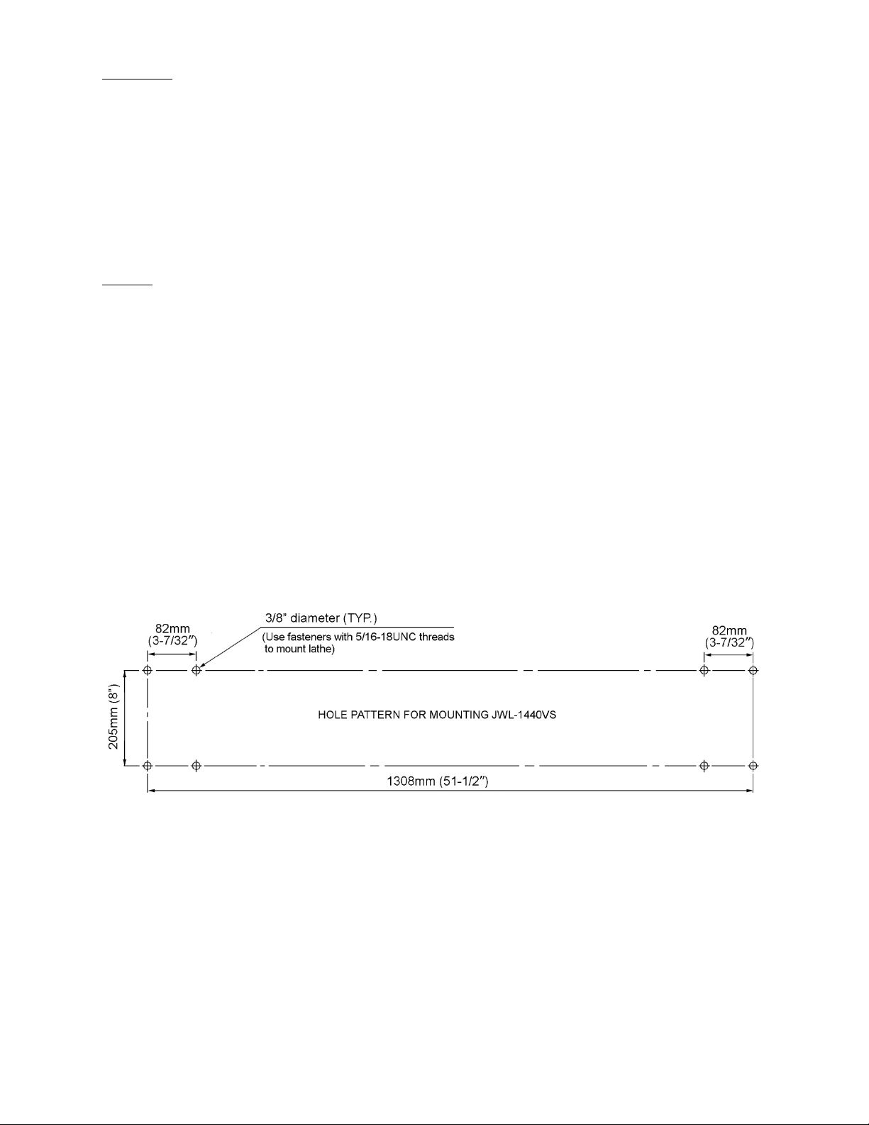
5.1 JWL-1440VS hole pattern
Figure 1
7
Page 8
6.0 Setup and assembly
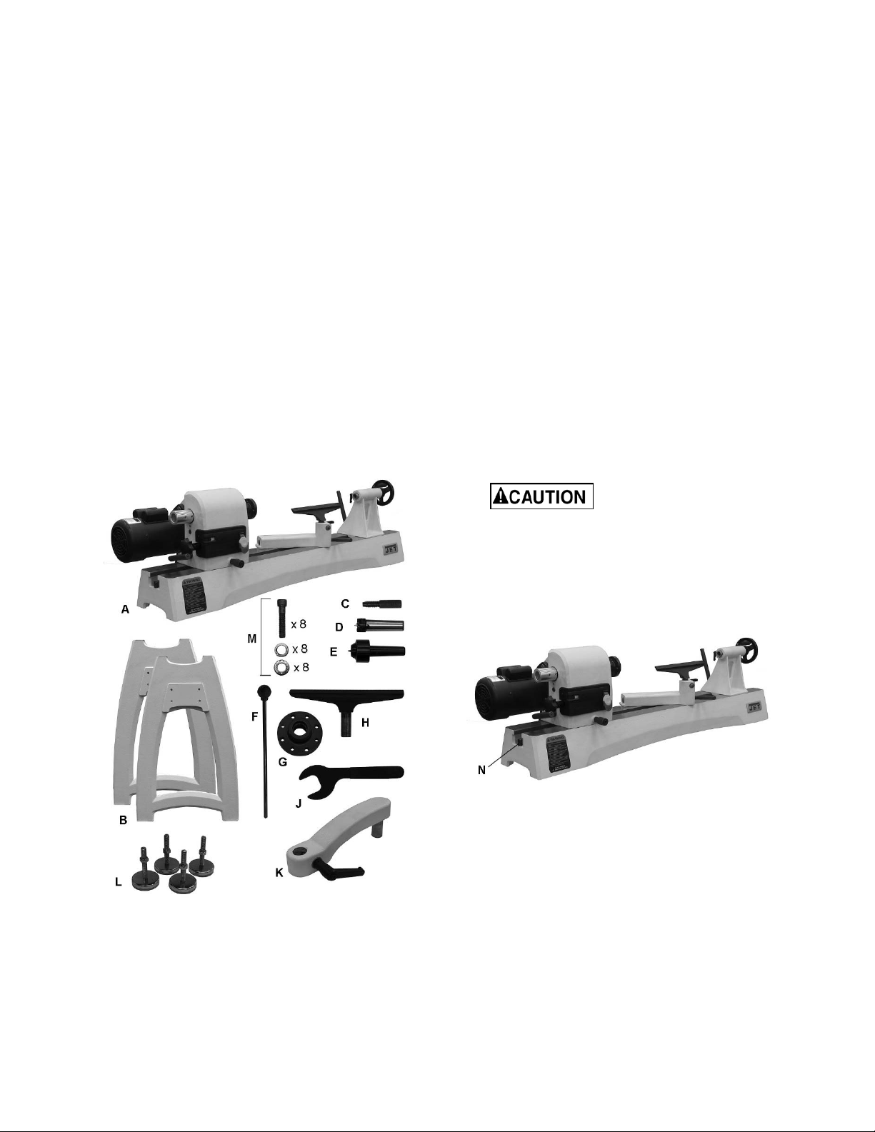
6.1 Shipping contents
Carton contents for # 719400K (see Figure 2)
1 Lathe bed with headstock, tool support and
tailstock – A
2 Legs – B
1 Spindle index pin – C
1 Spur center – D
1 Live cone center – E
1 Knockout rod – F
1 Faceplate – G
1 Tool rest – H
1 Faceplate wrench – J
1 Tool rest extension – K
4 Levelers – L
1 Operating Instructions & Parts Manual
1 Warranty Card
1 Hardware Package (JWL1440-HP1) – M
8 Socket Head Cap Screws, 5/16 X 1-1/4
8 Lock Washers, 5/16
8 Flat Washers, 5/16
6.2 Unpacking and cleanup
1. Remove all smaller items from main carton. Do
not discard carton or packing material until
lathe is assembled and running satisfactorily.
2. Inspect contents for shipping damage; if any is
found, report it to your distributor.
3. Compare contents of shipping carton with the
contents list in this manual. Report shortages,
if any, to your distributor. Note: Check lathe
first – some parts may have been pre-installed.
If you did not purchase the leg set and are
mounting the lathe to a bench or table, continue
with sect ion 6 .3. If yo u purc hase d t he leg set , sk ip
to section 6.4.
6.3 Mounting lathe to bench
1. Unscrew the stud (N, Figure 3) from each end
of the bed.
2. Loosen the locking handles on headstock, tool
rest and tailstock, and slide these items off the
bed. (Refer to section 8.0 for detailed
instructions on adjusting or removing these
items.)
The headstock is heavy.
Use an assistant to help remove.
3. Ref er to Figure 1 for mounting hole sizes and
spacing in the lathe bed. The bed has four
5/16”-18UNC threaded holes. Use appropriate
fast eners (bo lts and wa shers) to secure lathe
to bench or table from underneath.
Figure 3
6.4 Installing leg set
Refer to Figure 4.
6mm hex key required
Figure 2
(not to scale)
1. Unscrew the stud (N, Figure 3) from each end
of bed.
2. Remove headstock, tailstock and tool rest
support from bed. (Refer to sect. 8.0 for
detailed instructions on adjusting and
removing these items.)
3. Carefully turn bed upside down. Place a mat or
cardboard beneath it to prevent scratching the
bed ways.
8
Page 9
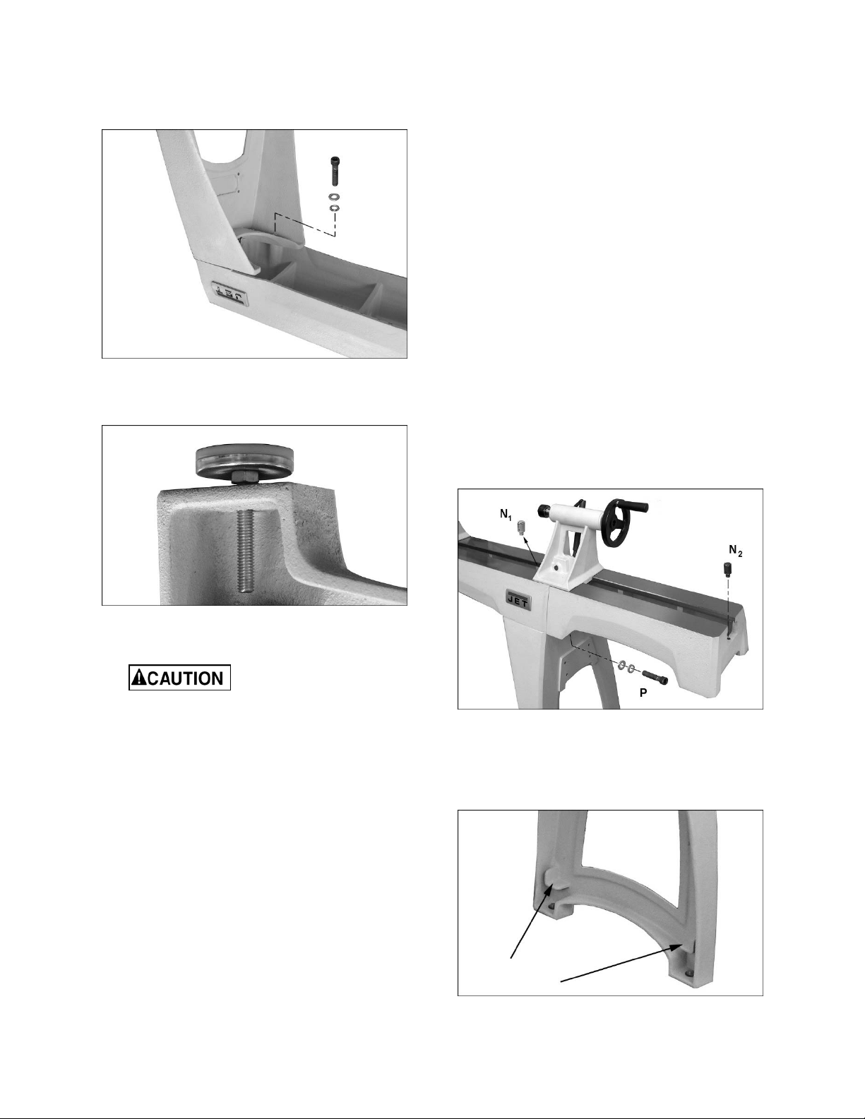
4. Install legs with eight 5/16” screws, lock
washers and flat washers (Figure 4), and 6mm
hex key.
5. Tighten screws firmly.
Figure 4
6. Install the four levelers (Figure 5). These can
be adjusted later.
1. Slide tailstock away from edge of bed.
2. Have an assistant hold bed extension flush to
end of lathe bed, and insert four 3/8” socket
head cap screws with lock washers and flat
washers, provided with the bed extension (P,
Figure 6). Snug screws just enough to hold
bed extension to lathe bed.
3. Unscrew stud from lathe bed (N1), and insert it
into hole at end of bed extension (N2).
4. Adjust bed extension to lathe bed, aligning the
surface and the inside ways as closely as
possible.
IMPORTANT: Top surface of bed extension
must be flush with surface of lathe bed, and
inside ways must be aligned, to allow smooth
movement of tailstock across joint.
5. Slide tailstock over joint where beds meet, so
that clamping nut is centered over joint (Figure
14). Lock tailstock clamping handle; this will
align the beds.
6. Securely tighten screws (P) in bed extension.
7. Unlock tailstock and slide it back and forth to
test smoothness of the joint. Make further
adjustments if needed.
Figure 5
7. With help from an assistant, raise bed and leg
assembly right-side up.
Bed and leg assembly is
heavy. Use care when lifting.
8. Rotate the levelers (Figure 5) as needed to
establish level for the lathe. Tighten the hex
nut on each leveler against the leg casting.
9. Install headstock, tool support and tailstock,
and both studs (N, Figure 3).
6.5 Mounting bed extension (optional
accessory)
8mm hex key required.
The 20” bed extension (p/n 719401) is optional and
purchased separately. See your JET dealer for
information. If you did not purchase the bed
extension, proceed to section 6.6.
The bed extension can be mounted to the upper or
lower holes of the lathe. Mounting in upper holes
increases the spindle length capacity of the lathe.
Mounting the extension to the lower holes allows
use of the tool support during outboard turning.
Figure 6
6.6 User-made storage shelf
A shelf may be constructed below the bed, using
the ledges inside the lathe legs (Figure 7).
Figure 7
9
Page 10
7.0 Electrical connections
Electrical connections must
be made by a qualified electrician in
compliance with all relevant codes. This
machine must be properly grounded to help
prevent electrical shock and possible fatal
injury.
The JWL-1440VS Lathe is rated at 115/230V
power, and is pre-wired for 115 volt. The lathe
comes with a plug designed for use on a circuit
with a grounded outlet that looks similar to the one
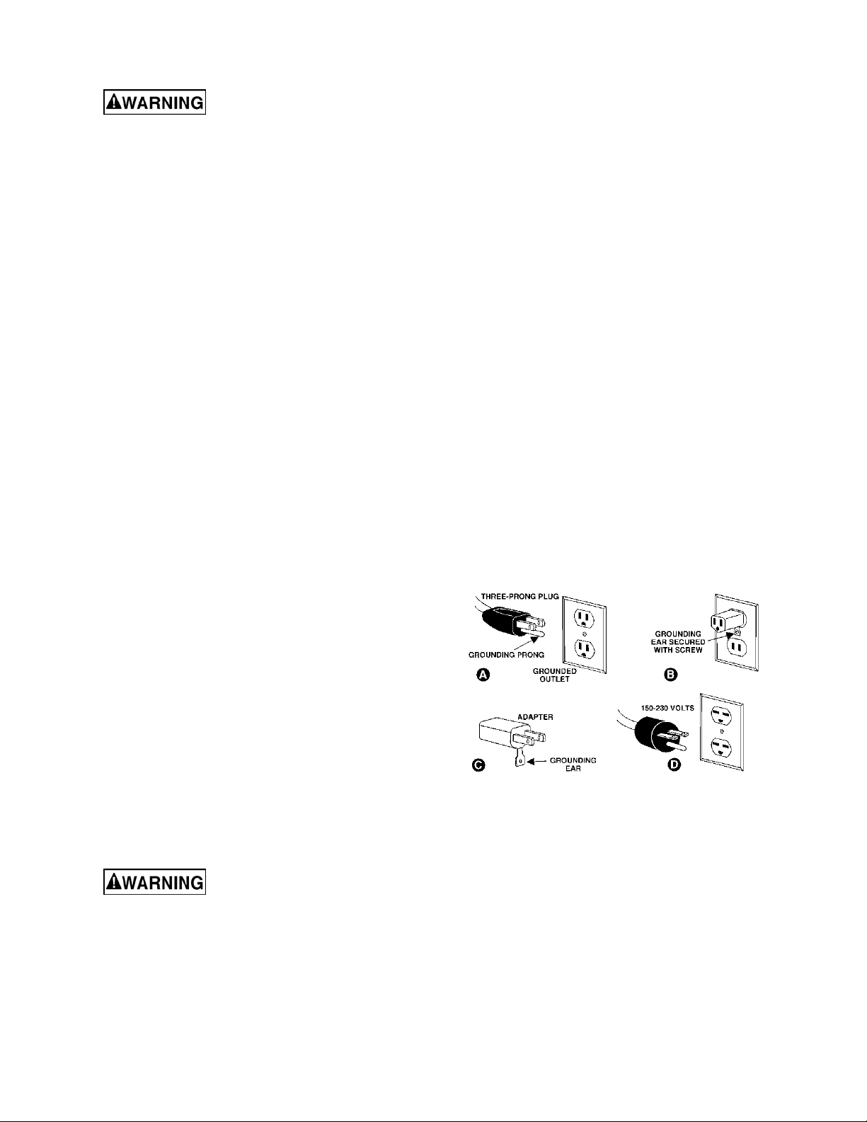
pictured in A, Figure 8.
Before connecting to power source, be sure switch
is in off position.
It is recommended that the lathe, when operated
on 115 volt power, be connected to a ded icated
20 amp circuit with a 20 amp circuit breaker or
time-delay fuse marked “D”. When operated on
230 volt power, it is recommended that the lathe
be connected to a dedicated 15 am p circuit with a
15 amp circuit breaker or time-delay fuse marked
“D”. Local codes take precedence over
recommendations.
7.1 Grounding instructions
1. All Grounded, Cord-connected Tools:
In the event of a malfunction or breakdown,
grounding provides a path of least resistance for
electric current to reduce t he risk of electr ic shock.
This tool is equipped with an electric cord having
an equipment-grounding conductor and a
grounding plug. The plug must be plugged into a
matching outlet that is properly installed and
grounded in accordance with all local codes and
ordinances.
Repair or replace damaged or worn cord
immediately.
2. Grounded, cord-connected tools intended for
use on a supply circuit having a nominal rating less
than 150 volts:
This tool is intended for use on a circuit that has an
outlet that looks like the one illustrated in A, Figure
8. An adapter, shown in B and C, may be used to
connect this plug to a 2-pole receptacle as shown
in B if a properly grounded outlet is not available.
The temporary adapter should be used only unt il a
properly grounded outlet can be installed by a
qualified electrician. This adapter is not permitted
in Canada. The green-colored rigid ear, lug, and
the like, extending from the adapter must be
connected to a permanent ground such as a
properly grounded outlet box.
3. Grounded, cord-connected tools intended for
use on a supply circuit having a nominal rating
between 150 - 250 volts, inclusive:
This tool is intended for use on a circuit that has an
outlet that looks like the one illustrated in D, Figure
8. The tool has a grounding plug that looks like the
plug illustrated in D. Make sure the tool is
connected to an outlet having the same
configuration as the plug. No adapter is available
or should be used with this tool. If the tool must be
reconnected for use on a diff erent type of electric
circuit, the reconnection should be made by
qualified service personnel; and after reconnection,
the tool should comply with all local codes and
ordinances.
Do not modify the plug provided - if it will not fit the
outlet, have the proper outlet installed by a
qualified electrician.
Improper connection of the equipment-grounding
conductor can result in a risk of electric shock. The
cond uctor with insulatio n having an o uter surface
that is green with or without yellow stripes is the
equipment-grounding conductor. If repair or
replacement of the electric cord or plug is
necessary, do not connect the equipmentgrounding conductor to a live terminal.
Check with a qualified
electrician or service personnel if the
grounding instructions are not completely
understood, or if in doubt as to whether the
tool is properly grounded. Failure to comply
may cause serious or fatal injury.
Use only 3-wire extension cords that have 3-prong
grounding plugs and 3-pole receptacles that accept
the tool's plug.
Figure 8
7.2 Voltage conversion
To switch the incoming power leads for 230 volt
operation:
1. Remove the junction box cover on the motor
and reconnect the leads according to the
diagram inside the cover. A similar diagram is
found at the back of this manual. (Note: In the
event of discrepancies, the diagram inside
junction box takes precedence.)
2. Remove the 120V plu g on the end of the motor
cord and replace it with a UL/CSA listed plug
rated for 240V.
10
Page 11

Alternatively, the lathe m ay be “hard-wired” to
the power source. If you are hard-wiring the
lathe to a panel, make sure a disconnect is
available for the operator. During hard-wiring
of the Lathe, make sure the fuses have been
removed or the breakers have bee n tripped in
the circuit to which the Lathe will be
connected. Place a warning placard on the
fuse holder or circuit breaker to prevent it
being turned on while the machine is being
wired.
7.3 Extension cords
The use of extension cords is discouraged; try to
position equipment within reach of the power
source. If an extension cord becomes necessary,
be sur e it is heav y e no ugh to ca r ry the c ur rent your
product will draw. An undersized cord will cause a
drop in line voltage resulting in loss of power and
overheating.
Table 1 shows recommended size to use
depending on cord length and nameplate ampere
rat ing . If in d o ubt , use t he ne xt hea v ie r g a uge . T he
smaller the gauge number, the heavier the cord.
4. Release knob (B) and it will seat itself with an
audible click when the headstock reaches a
positive lock position.
5. Tighten handle (A) by pulling it away f rom the
motor.
6. Rotate knob (B) clockwise until it e ngages the
threads.
Always tighten handle (A)
firmly before operatin g lath e.
Ampere
Rating
More
Than
00 06 18 16 16 14
06 10 18 16 14 12
10 12 16 16 14 12
12 16 14 12
Not
More
Than
Extension Cord Recommendations
Volts
120
240
AWG
Total length of
cord in feet
25
50
50
100
Table 1
100
200
Not
Recommended
150
300
8.0 Adjustments
8.1 Headstock sliding
Push handle (A, Figure 9) tow ard motor to unlock.
Headstock will slide freely alo ng the length of the
bed. Retighten handle before operating lathe.
8.2 Headstock rotation
1. Loosen handle (A, Figure 9).
2. Unscrew the knurled knob (B) counterclockwise until it can be pulled outward.
3. Pull knob outward and rotate headstock to
desired position. The headstock has seven
positive locking positions. NOTE: Be careful
not to pinch your fingers against the bed as
you rotate the headstock.
Figure 9
8.3 Tailstock movement
To slide tailstock, push locking handle (C, Figure
10) down toward the bed. Push locking handle
upright to lock tailstock in position.
To mo ve the q uil l, loo sen the lock handle (D) a nd
rotate the handwheel (E).
Make sure tailstock is locked
to bed (C, Figure 10) a nd quill is tightened (E)
before turning a spindle on the lathe.
Figure 10
To remove headstock, tailstock or toolrest base
from bed, unscrew and remove either of the studs
(see N, Figure 3). A fter rem ounting these item s on
the lathe, reinstall studs.
For most turning operations, except outboard
turning, the headstock is positioned at the left end
of bed, and the tailstock moved to accommodate
the workpiece.
11
Page 12

8.4 Cam tightness
8.6 Tool rest extension
The clamping mechanisms of headstock, tailstock
and tool rest base are pre-set by the manufact urer,
and should not require adjustment.
If one of them does not tighten properly against the
bed when the locking handle is tightened, adjust it
as follows. (Figure 11 uses the tailstock as the
example.)
Figure 11
1. Remove stud from end of lathe bed, and slide
tailstock off.
2. Turn tailstock on its side, and tighten lock nut
(F, Figure 11) to increase cam pressure, or
loosen the nut to relieve cam pressure.
3. Mount tailstock on bed and lock it to verify
adjustment. Repeat as needed.
4. Reinstall stud.
8.5 Tool rest
A 12-inch tool rest is provided with your lathe. It is
designed to allow adjustment for height, position on
the bed, and angle to the work.
Loosen locking handle on tool rest base (G, Figure
12) to slide base forward or back, and to angle it to
the bed. Tighten locking handle firmly before
operating lathe.
The extension (J, Figure 13) mounts to the tool rest
base and offers greater reach for the tool rest when
turning off the bed using the headstock at an
angle, as shown.
Make sure the clamp bushings (K, Figure 13) are
pulled apart sufficiently to accept the post of the
extension.
Figure 13
8.7 Locking handles
Locking handles, such as H, Figure 12, are
adjustable. Simply lift out on handle, rotate it on the
pin, t hen relea se it, making sure it seats itself o n
the pin.
8.8 Spindle indexing
Indexing is used to create evenly spaced features
in a work piece, while keeping the lathe spindle
locked; for example, when cutting flutes on a
spindle blank with a hand-held router, while the
spindle blank is secured between lathe centers.
The JWL-1440VS lathe provides 36 indexing
positions. These are identified in the chart in
section 15.0.
Loosen handle (H, Figure 12) to raise or lower tool
rest and angle it to the work. Tighten handle before
operating lathe.
Figure 12
Figure 14
1. Rotate spindle using the handwheel until the
index pin (L, Figure 14) aligns with the desired
hole .
2. Screw the index pin into the hole until it
engages the spindle.
12
Page 13

3. Perform the desired procedure.
4. Unscrew the index pin until the spindle is
released. Rotate spindle to next desired hole,
and repeat.
Remove spindle index pin
before starting lathe.
IMPORTANT: Do no t use index p i n t o l o c k spindle ,
which will cause unnecessary wear to the pin. U se
spindle lock for this purpose.
8.9 Spur center: Installing/removing
The live center is installed into the headstock
spindle. The live center should first be mounted to
your workpiece, and then installed into the spindle.
See section 10.4.
1. Disconnect lathe from power source.
2. Clean the tapered end of the center, and the
inside of the headstock spindle, then push the
center into the headstock spindle.
3. To remove a live center, first remove
workpiece from lathe. Insert knockout rod
(Fig ur e 1 5) t hro ugh ho le i n ha ndw hee l a nd t ap
the tapered end of the spur center.
IMPORTANT: Hold the center by either
placing your thumb and forefinger on outside
diameter of spur center, or wrapping the center
with a rag. The center can be damaged if
allowed to fall.
sure the keyway (N, Figure 16) in the quill is
aligned with the locking handle.
To remove the live center:
4. Back off the tailstock and remove workpiece
from lathe.
5. Loosen quill lock handle (M, Figure 16).
6. Rotate the handwheel counterclockwise to
retract quill all the way, until the live center
comes out. Hold the center while doing this to
prevent it from falling.
Figure 16
8.11 Spindle lock
Push spindle lock pin (P, Figure 17), and rotate the
spindle slightly until the pin goes entirely into the
recess. Continue to hold spindle lock pin in the
recess.
Figure 15
8.10 Live center: Installing/removing
The live center is installed into the tailstock quill.
1. Disconnect lathe from power source.
2. Clean the tapered end of the center and the
inside of the tailstock quill, then push the
center into the quill. Test the insertion by
attempting to pull the center out of the quill by
hand. It should remain secure within the quill.
3. Always tighten the quill locking handle (M,
Figure 16), once the live center has been
properly positioned in the workpiece. Make
Figure 17
8.12 Face plate: Installing/removing
1. Disconnect lathe from power source.
2. Mount the face plate to your workpiece.
3. Engage spindle lock pin.
4. Install face plate onto threads of headstock
spindle and rotate clockwise as far as it will go.
5. Face plate is now ready for turning.
6. To remove the face plate, engage spindle lock,
and turn face plate counterclockwise with face
plate wrench.
13
Page 14

8.13 Checking center alignment
When the headstock is returned from outboard
position, the alignment between centers should be
checked.
1. Lock the headstock in normal spindle turning
position.
2. Slide the tailstock toward the headstock until
the centers almost touch (see Figure 18). Lock
the tailstock in position.
3. View the center points from top and side to
make sure they align.
4. If the centers do not align, unlock the
headstock and pivot it slightly. There should be
enough “play” in the headstock to adjust for
this alignment. Lock the headstock when
finished.
Figure 18
9.0 Operating controls
Refer to Figure 19.
Speed control handle: Rotate handle (B, Figure
20) to set speed, which is displayed as RPM
(revolutions per minute) in the adjoining window
(C).
Do not start lathe at maximum
speed when a workpiece is mounted in the
lathe. Start at lower speed and gradually
increase to desired speed.
Figure 20
The JWL-1440VS contains a Reeves or “splitpulley” system.
As speed is increased, via the speed change
handle, the spindle pulley widens and the belt
drops down to the smaller diameter between the
pulley halves. Conversely, the motor pulley, which
is spring-loaded so that it adj usts automatically to
the movement of the spindle pulley, gets narrower,
drawing the belt outward toward the larger
diameter. When the speed is decreased, the
pulleys act in opposite fashion.
On/off switch (A): Pull to start lathe, push to stop.
The safety key (A1) can be removed to prevent
unauthorized use of lathe. The safety key must be
inserted to restart the lathe.
Figure 19
If a power outage should
occur during operation, the lathe will
immediately restart when power is resumed if
the start switch is still engaged. Push switch
immediately to OFF position in the event of a
power outage.
Change speed while the lathe
spindle is turning to avoid overstressing the
belt.
10.0 Operation
The information which follows is general in nature
and not intended to be a complete course in
woodturning. Nothing can replace the knowledge
gained by talking with experienced woodturners or
consulting books or trade magazines. Above all,
simple trial and error will aid in developing
proficiency in the craft.
10.1 Inspection
Before operating the lathe, check that everything is
in proper working order:
1. Level your machine; use the leveling feet to
help reduce vibration.
2. Check bearings; adjust only if endplay exists.
3. Check belt; it should be snug but not overly
tight.
14
Page 15

4. Bed ways; keep clean, use steel wool to
remove any rust spots, and apply paste wax to
prevent buildup of rust and finishes.
5. Tool rest; use a mill file to remove nicks and
dings.
6. Spindle tapers; should be clean and free of
dust and chips for proper seating of tapers.
7. Tailstock; clean and lubricate quill and locking
device.
8. Lighting; proper lighting is essential to
eliminate shadows and reduce eye strain.
10.2 Turning Tools
If possible, select only quality, high-speed steel
turning tools. High-speed steel tools hold a n edge
and last longer than ordinary carbo n steel. As one
becomes proficient in turning, a variety of specialty
tools for specific applications can be acquired. The
following tools provide the basics for most
woodturning projects (see Figure 21):
Skews – 1-1/2" and 1" or 1-1/4", used to make
finishing cuts and details.
Large Roughing Gouge – 1" to 1-1/4", used to
eliminate waste wood.
Spindle Gouges – 1/4", 3/8", 1/2", used to turn
beads, coves and other details.
Deep Fluted Bowl Gouge – 1/4", 3/8" and 1/2",
used for turning bowls & plates.
Square Scraper (Bedan) – 3/8” or 1/2", used to
create square shoulders.
Large Round Nose (Domed) Scraper – 1-1/2",
used to reduce ridges on interior of bowls, round
edges of bowls, etc.
Parting Tool - 1/8", used for scraping, making a
cut-off, or to set diameters for sizing.
For safety and best performance, keep tools sharp.
If a tool stops cutting or requires excessive
pressure to make a cut, it needs to be sharpened.
A number of brand name sharpening jigs and
fixtures are available; however, a woodturner
should learn to sharpen tools freehand.
For best results, use a slow speed grinder (1800
rpm) fitted with a 60-grit a l uminum oxide wheel (f or
shaping) and a 100-grit alum. o xide wheel (f or f inal
sharpening and touchup). The grinder should be
located near your lathe and at a comfortable
height. A diamond dresser will keep the wheels
true and eliminate glazing.
Figure 21
Basic Turning To ols
Carbon steel tools can over heat easily and should
be cooled frequently. If the edge turns blue, it has
lost its temper and should be ground past t he blue
area. High-speed steel tools are not as likely to
overheat, but can be damaged if allowed to get red
hot. High-speed steel tools should not be
quenched for cooling. Honing with a diamond lap
or slipstone will save trips to the grinder and keep
the edge fresh.
10.3 Spindle Turning
Spindle turning takes place between the centers of
the lathe. It requires a spur or drive center in the
headstock and a live or dead center in the tailstock.
A cup center rather than a cone center in the
tailstock will often reduce the risk of splitting the
stock.
Figure 22 shows the basic profile shapes in spindle
turning.
Never allow the tool to rest in one place on the
wheel, keep it moving and use a light touch.
Figure 22
15
Page 16

10.4 Stock Selection
Stock for spindles should be straight grained and
free of checks, cracks, knots and other defects. It
should be cut 1/8" to 1/4" larger than the fini shed
diameter and may require additional length so the
ends can be removed later. Larger stock should
have the corners removed to produce an octagon
making the piece easier to rough down to a
cylinder.
1. With a combination square, or plastic center
finder for round stock, locate and mark center
on each end of the workpiece. Accuracy is not
critical on full rounds but extremely important
on stock where square sections are to remai n.
Put a dimple in the stock with an awl or nail, or
use a spring-loaded automatic center punch.
2. Extremely hard woods may require kerfs cut
into the ends of the stock (Figure 23) using a
band saw, so the wood will accept the spur
center and the live center.
Never use a steel face
hammer and never drive the workpiece
onto the spur center while it is mounted in
the Lathe spindle.
4. Make sure headstock is locked to lathe bed.
5. Clean tapered end of spur center a nd i nside of
headstock spindle.
6. Insert tapered end of spur center (with the
attached workpiece) into headstock spindle.
7. Support the workpiece while bringing the
tailstock into position about 1-inch away from
end of workpiece. Lock tailstock to bed.
8. Advance tailstock quill with the handwheel in
order to seat the live center into the workpiece.
Use enough pressure to secure the workpiece
between the centers so that it won’t f ly off, but
do not use excessive pressure.
9. T ig ht en quill loc king ha ndle .
The tailstock quill is capable
of exerting excessive pressure against the
workpiece and the headstock. Apply only
sufficient force with tailstock to hold workpiece
securely in place. Excessive pressure can
overheat center bearings and damage both
workpiece and lathe.
Figure 23
3. Drive the spur center about 1/4” into the
workpiece, using a wood mallet or dead b low
hammer as shown in Figure 24. Be careful that
you do not split the workpiece.
10. Move tool rest into position. It should be
parallel to workpiece, just below the centerline
and approximately 1/8" to 1/4" from the
corners of the workpiece to be turned, as in
Figure 25. Tighten tool rest base to Lathe bed.
11. Rotate workpiece by hand to check for proper
clearance.
12. Start lathe at lowest speed and bring it up to
the appropriate RPM for the size of work piece
used. Consult digital readout on the
headstock.
Figure 25
Figure 24
16
Page 17

10.5 Cutting Techniques
10.5.3 Coves
10.5.1 Roughing Out
1. Begin with a large ro ughing gouge. Place the
tool on the tool rest with the heel of the tool on
the surface to be cut.
2. Slowly and gently raise tool handle until cutting
edge comes into contact with the workpiece.
3. Beginning about 2” from the tailstock end of
the workpiece, roll the flute (hollowed-out
portion) of the tool in the direction of the cut.
See Figure 26. Make lo ng sweeping cuts in a
cont in uous m otio n to r oug h the p iece down t o
a cylinder.
4. Keep as much of the bevel of the tool as
possible in contact with the workpiece to
ensure control and avoid catches. NOTE:
Always cut down-hill, or from large diameter to
small diameter. Always work toward the end of
a work-piece, never start cutting at the end.
1. Use a spindle gouge. W ith the flute of the tool
at 90 degrees to the workpiece, touch the point
of the tool to the workpiece and roll in toward s
the bottom of the cove. See Figure 27. Stop at
the bottom; attempting to go up the
opposite side may cause the tool to catch.
Figure 27
2. Move the tool over the desired width of the
cove.
3. With the flute facing the opposite direction,
repeat step 1 for other side of cove. Stop at
bottom of cut.
Figure 26
5. Once the workpiece is roughed down to a
cylinder, smooth it with a large skew. Keep t he
skew handle perpendicular to the spindle and
use only the center third of the cutting edge for
a long smoothing cut (touching one of the
points of the skew to the spinning workpiece
may cause a catch and ruin the workpiece).
6. Add details to the workpiece with skew, parting
tool, scraper or spindle gouge.
10.5.2 Beads
1. Make a parting cut for what is to be a bead to
the desired depth. Place the parting tool on the
tool support and move tool forward to make
the full bevel of the tool come into contact with
the workpiece. Gently raise handle to make cut
to the appropriate depth.
2. Repeat for other side of the bead.
3. Using a small skew or spi ndle gouge, start in
the center between the two cuts a nd cut down
each side to form the bead. Roll the tool in
direction of cut.
10.5.4 "V" Cuts
1. Use the long point of the skew. (NOTE : Do not
press the long point of the skew directly into
the workpiece to create the "V"; this will result
in a burned or burnished "V" with fibers being
rolled up at both sides.)
2. Lightly mark the center of the "V" with the tip of
the skew.
3. Move the point of the skew to the right half of
the desired width of your cut.
4. With the bevel parallel to the right side of the
cut, raise the handle and push the tool in to the
desired depth, as shown in Figure 28.
Figure 28
5. Repeat from the left side. T he two cuts should
meet at the bottom and leave a clean "V" cut.
17
Page 18

6. Additional cuts may be take n to add to e ither
the depth or width of the cut.
10.5.5 Parting Off
1. Use parting tool.
2. Adjust lathe speed to lower RPM for parting
through a workpiece.
3. Place tool on tool support and raise the handle
until it starts to cut and continue to cut toward
center of workpiece.
4. Loosely hold on to the piece in one hand as it
separates from the waste wood.
10.5.6 Sanding and Finishing
Leaving clean cuts will reduce the amount of
sanding required. Move the tool support out of the
way, adjust the lathe to a low speed, and begin
with fine sandpaper (120 grit or finer). Coarser
sandpaper will leave deep scratches that are
difficult to remove, and dull crisp details on the
spindle. Progress through each grit without
skipping grits (for e xample, do not jump from 120
grit to 220 grit). Fold the sandpaper i nto a pad; do
not wrap sandpaper around your fingers or the
workpiece.To apply a finish, the workpiece can be
left on the lathe.
metal screws are case hardened with deeper
and sharper threads than wood screws.)
If the mounting screws on the face plate interfere
with the workpiece, a glue or waste block can be
used:
5. Make a block the same diameter as the face
plate, Figure 29. Both waste block and
workpiece should have flat surfaces for gluing.
6. Glue the block to the workpiece. Avoid using
brown paper or newspaper between the waste
block and workpiece. It may work fine if you
are using scrapers, but a slight catch with a
bowl gouge can separate the two.
NOTE: When using a waste block, be careful with
the adhesive you select. Dry workpieces can be
bonded with ordinary white or yellow glue but must
be clamped to ensure a good bond. Green
workpieces require cyanoacrylate type glue.
Turn off lathe and use a brush or paper towel to
apply the finish. Remove excess finish before
restarting lathe. Allow to dry and sand again with
320 or 400 grit sandpaper. Apply second coat of
fin ish and buff.
10.6 Face Plate and Bowl Turning
Face plate turning is normally done o n the inboard
side of the headstock over the bed. Larger
workpieces must be turned on the outboard side
(remove tailstock and tool support base, and slide
headstock to opposite end of bed).
10.6.1 Mounting Stock
Use of a face plate is the most common method for
holding a block of wood for turning bowls and
plates:
1. Select stock at least 1/8" to 1/4" larger than
each dimension on the finished workpiece.
2. Always select the largest diameter face plate
that can be used for the workpiece to be
turned.
3. True one surface of the workpiece for
mounting against the face plate.
4. Using the face plate as a template, mark the
location of the mounting holes on the
workpiece, and drill pilot holes of the
appropriate size. Face plates are drilled for No.
12 screws. (Phillips and square drive screws
will hold up better than slotted screws. Sheel
Figure 29
10.6.2 Faceplate or Chuck?
While faceplates are the simplest, most reliable
method of holding a block of wood for turning,
chucks can also be used. As there are dozens of
chucks to choose from, the woodturner should first
consider all the different t ypes of turning that will be
done, and read reports or discuss with other
turners who own chucks before making a decision.
A chuck i s not a requirement, but is hand y whe n
working on more than one piece at a time. Rather
than re mov ing scre ws, yo u simp ly ope n the ch uck
and change workpieces.
The most popular ones are four jaw scroll chucks
with a variety of jaws to accommodate different
size tenons. Most also come with a screw chuck as
well.
18
Page 19

10.6.3 Wood Selection
Firewood is the cheapest, most widely available
stock to use while learning to turn bowls. Simply
waste wood for a while practicing turning
techniques. Develop skill with each tool before
attempting to make a finished piece. It is best to
start with dry wood, without worrying about drying
or distortion. Once turning becomes comfortable,
try green wood which cuts very easily. As the
turner gains experience, he or she will find
extraordinary grain and figure in the f orm of burls,
crotches and bark inclusions.
10.6.4 Checks and Cracks
Green wood will check and crack. For best results,
lea ve log s in as lo ng a le ngth a s you c an hand le.
As the material starts to dry, surface cracks will
develop on the ends of the log. Cut off two to three
inches and you should find good, sound wood.
Also cut the log in half along the pith to avoid
having it in the finished piece. Most checks radiate
from the pith.
As you turn bowls from green wood, make sure
you maintain a consistent wall thickness
throughout the piece. Leaving a piece thick in
some areas and thin in others will cause the wood
to dry unevenly and promote checks and cracks.
10.6.5 Distortion
Distortion is a problem associated with turning
green wood. It will vary from one type of wood to
the next. Typically, fruitwoods tend to distort more
than others. It also varies with the time of year the
tree was cut and how the logs are stored.
10.6.6 Tools for Bowl Turning
The deep fluted bowl gouge is the m ost essential
and versatile tool for most bowl and plate turning.
The bowl gouge is heavier and easier to control
than other types of gouges. It also allows removal
of wood much faster and with less vibration than
other gouges. Most average sized bowl work can
be accomplished with a 3/8" or 1/2" bowl gouge.
A 1/4" bowl gouge is best suited f or smaller bowls
and light finishing cuts. Larger 3/4" and 1" bowl
gouges are only used for extremely large pieces.
from what appears to be the center of the top
of the workpiece.
2. Drive spur center into the top of t he workpiece
with a mallet or dead blow hammer.
3. Slip the spur center into the headstock taper
and bring the tailstock with a live or ball
bearing center into position. Lock the tailstock
to the bed and advance the tailstock spindle in
order to seat the cup center into the
workpiece. Tighten the ram locking handle.
4. Turn workpiece by hand to ensure proper
clearance.
5. Start lathe at lowest speed and bring it up to
the maximum safe speed for the size of work
to be turned. If the machine starts to vibrate,
lower the speed until vibration stops.
6. Rough out the outside of the bowl with the 1/2"
deep fluted bowl gouge, holding the handle of
the tool firmly against your hip. For best
control, use your whole body to move the
gouge through the workpiece.
7. As the bowl takes shape, work on the bottom
(tailstock end) to accommodate attaching a
face plate.
8. Turn a short tenon (about 1/8" long) the size of
the hole in the faceplate. See Figure 30. This
will allow centering the workpiece when the
faceplate is attached.
(NOTE: If you plan to use a chuck, turn a
tenon of the appropriate length and diameter
to fit your chuck.)
9. Stop the lathe, remove workpiece and attach
face plate or chuck (see section 10.6.1
"Mounting Stock").
The surfaces of faceplate
and workpiece should mount flush to each
other.
10. Finish turning the outside of bowl with 1/2" or
3/8" bowl gouge. Leave additional material at
base of bowl for support while turning interior.
This will be removed later.
Large domed scrapers can also be used to help
clean up the interior surfaces of bowls. A light
touch with the scraper slightly tilted will eliminate
some of the ridges occasionally left by an
inexperienced bowl gouge.
10.7 Bowl Turning Techniques
10.7.1 To Shap e Out s ide of Bowl
1. Odd shaped burls, crotches and other irreg ular
shaped blanks require special preparation
before mounting in a chuck or onto a
faceplate. Remove the bark, if there is any,
Figure 30
19
Page 20

10.7.2 To Shape Interior of Bowl
1. Stop lathe and move tailstock away. (You may
want to remove the center from the tailstock to
avoid bumping it with your elbow.)
2. Adjust tool support in front of the bowl just
below centerline, at a right angle to the lathe
ways.
9. Begin the separation with a parting tool, b ut do
not cut all the way through yet.
10.7.3 Sanding and Finishing
1. Remove the tool support and adjust lathe
speed to approximately 500 RPM. Higher
speeds can build friction while sanding and
cause heat check in some woods.
3. Rotate workpiece by hand to check clearance.
4. Face off top of bowl by making a light shearing
cut across the top of workpiece, from rim to
center.
5. Place 1/2" bowl gouge on tool support at
center of the workpiece with the flute facing
top of bowl. The tool handle should be level
and pointed toward the four o'clock position, as
shown in Figure 31.
Figure 31
6. Use the left hand to control cutting edge of
gouge, while right hand swings tool handle
toward your body (Figure 31). The flute should
start out facing top of workpiece, and rotate
upward as it moves deeper into the bowl to
maintain a clean even curve. As the tool goes
deeper into the bowl, progressively work out
toward the rim. It may be necessary to turn the
tool support into the piece as you get deeper
into the bowl.
2. Begin with fine sandpaper (120 grit) and
progress through each grit, using only light
pressure. Coarser sandpaper tends to leave
deep scratches that are hard to eliminate. Use
power-sanding techniques to avoid concentric
sanding marks around your finished piece.
Avoid rounding over the rim and foot with
sandpaper; try to keep details crisp. Finish
sanding with 220 grit.
3. Remove sanding dust with tack rags or
compressed air and, with lathe turned off,
apply first coat of finish. Let sta nd for several
minutes, wipe off excess. Allow to dry before
sanding again with 320 or 400 grit sandpaper.
4. Turn lathe back on and continue the
separation cut almost all the way through the
base. Stop at about 3" and use a small fine
tooth saw to separate the bowl from the waste.
5. Apply second finish coat and allow to dry
before buffing.
(NOTE: Try to make one, very light continuous
movement from the rim to the bottom of the
bowl to ensure a clean, sweeping curve
through the piece.
Should there be a few small ridges left, a light
cut with a large domed scraper can even out
the surface.)
7. Develop wall thickness at the rim and maintain
it as you work deeper i nto the bowl (Once the
piece is thin toward the bottom, you cannot
make it thinner at the rim). When the interior is
finished, move the tool support to exterior to
re-define bottom of bowl. (General rule of
thumb: the base should be approximately 1/3
the overall diameter of the bowl).
8. Work the tight area around faceplate or chuck
with 1/4" bowl gouge.
20
Page 21

11.0 Maintenance
Before doing mainte nance o n
the lathe, disconnect it from the electrical
supply by pulling out the plug or switching off
the main switch. Failure to comply may cause
serious injur y.
11.1 General procedures
Maintenance on the lathe should be perf ormed at
periodic intervals to ensure that the machine i s in
proper working order, that all fasteners are tight,
and all necessary adjustments have been made.
Inspection and maintenance should be performed
at least twice a year, but more frequently if the
lathe receives constant use.
Clean and oil the lathe bed so that headstock,
tailstock and tool rest base will slide easily. Clean
any rust spots that may develop on the bed with a
commercial rust remover.
Use compressed air to blow out the interior of the
headstock, in order to keep sawdust and chips
from accumulating on belts and sheaves. Also blow
off debris that accumulates in the motor fan.
Frequently clean out the morse tapers on both
headstock and tailstock. Commercially available
taper cleaners may be acquired from tool stores.
purpose grease into the zerk fitting on the motor
shaft (Figure 32) and the groove of the main
spindle (Figure 33).
Figure 32
Figure 33
Bearings are permanently lubricated and sealed,
and do not require further lubrication.
11.2 Pulley lubrication
After every 200 working hours, or every 30 days,
use a grease gun to insert a good quality, all-
11.3 Belt and bearings replacement
Changing belt and bearings can be a difficult task,
and should be performed by a JET authorized
service center. Remove headstock and take it to a
service center for servicing.
12.0 Optional accessory
This accessory item, purchased separately, can enhance the functionality of your lathe. Contact your dealer to
order, or call JET at the phone number on the cover.
719401 ...... 20" Extension Bed w/ Post
21
Page 22

13.0 Troubleshooting the JWL-1440VS Lathe
Table 3
Symptom Possible Cause Correction
Motor fails to develop
full power.
Motor or spindle stalls
or will not start.
Excessive vibration. Workpiece warped, out of round, has
Tools tend to grab or
dig in.
Headstock moves
when applying
pressure with
Tailstock.
Tailstock moves when
applying pressure.
Power line overloaded. Correct overload condition.
Undersized wires in supply system, or
extension cord is too long.
Running capacitor is bad. Replace running capacitor.
Worn motor. Replace motor.
Excessive cut. Reduce depth of cut.
Worn or broken belt. Replace belt.
Improper cooling of motor.
Starting or Running capacitor is bad. Replace capacitor.
Centrifugal switch is bad. Replace centrifugal switch.
Worn spindle bearings. Replace bearings.
Worn motor. Replace motor.
major flaw, was improperly prepared for
turning, or RPM is set too high.
Worn spindle bearings. Replace spindle bearings.
Worn drive belt. Replace drive belt.
Motor mount bolts are loose. Tighten bolts.
Lathe on uneven surface. Adjust leveling feet.
Dull tools. Keep tools sharp.
Tool rest set too low. Reposition tool rest height.
Tool rest set too far from workpiece. Reposition tool rest closer to workpiece.
Improper tool being used. Us e correct tool for operation.
Loc k i ng handl e no t t i ght. Tig ht en handle.
Excessive pressure being applied by
tailstock.
Cam lock nut needs adjusting. Tighten cam lock nut.
Excessive pressure being applied by
tailstock.
Lathe bed and tailstock mating surfac es
are greasy or oily.
Increase supply wire size.
Blow out sawdust from motor housing
fan.
Correct problem by planing or sawing
workpiece, or discard entirely and use
new workpiece. Reduce RPM.
Slide headstock to left end, lock firmly,
then apply pressure to workpiece with
tailstock. Apply only sufficient force with
tailstock to hold workpiece securely in
place.
Slide tailstock to right side of lathe
against the stop. Move headstock into
position and apply pressure to
workpiece with tailstock.
Remove tailstock and clean surfaces
with a cleaner/degreaser. Re-apply light
coat of oil to lathe bed surface.
22
Page 23

14.0 Recommended Lathe Speeds (per diameter of workpiece)
Diameter of Work Roughing RPM General Cutting RP M Finishing RPM
Under 2” 1520 3000 3000
2” to 4” 760 1600 2290
4” to 6” 510 1080 1500
6” to 8” 380 810 1125
8” to 10” 300 650 900
10” to 12” 255 540 750
12” to 14” 220 460 640
Table 4
23
Page 24

15.0 Indexer Positions
How to use the chart
A diagram of the indexer is shown at right, as
viewed from the tailstock end of the Lathe. Points
A, B and C are the holes in t he head casting. The
holes in the spindle collar may be considered as
numbered 1 through 12.
Example: You wish to rout 9 fl utes on your sp indle
blank. Locate the “9” in t he “No. of Flutes” col umn;
each flute angle will be 40°. The index pin should
first be inserted into hole combination “A-1”. Make
your first flute at this position. Back off the index
pin and rotate the spindle until the index pin can be
inserted into hole combination “A-5”; this will be
followed by “A-9”. Succeeding fl utes will be m ade
with the index pin in the B position: “B-3”, “B-7” and
so on
No. of Fl utes
360° divided by...
1 360.00 A 1
2 180.00 A 1,7
Angle Letter # Letter # Letter #
3 120.00 A 1,5,9
4 90.00 A 1,4,7,10
5 72.00 -----------------------
6 60.00 A 1,3,5, 7,9,11
8* 45.00 A 1,4,7,10
9 40.00 A 1,5,9 B 3,7,11 C 1,5,9
10 36.00 -----------------------
12 30.00 A 1 to 12
15 24.00 -----------------------
16 22.50 -----------------------
18 20.00 A 1,3, 5,7, 9,11 B 1,3,5,7,9,11 C 1,3,5,7,9,11
20 18.00 -----------------------
24* 15.00 A 1 to 12
30 12.00 -----------------------
36 10.00 A 1 to 12 B 1 to 1 2 C 1 to 12
other inte resting patter n s. ...
9 ------ A 1,5,9 B 1,5,9 C 1,5,9
NOTE: A dashed line indicates that particular set of angles is not possible with the indexer.
* For 8 or 24 flutes, perform the first sequence, then rotate the workpiece by hand to the needed position and repeat
the same sequence.
24
Page 25

16.0 Replacement Parts
Replacement parts are listed on the followi ng pages. To order parts or reach our service departm ent, call 1800-274-6848 Monday through Friday, 8:00 a.m. to 5:00 p.m. CST. Having the Model Number and Serial
Number of your machine available when you call will allow us to serve you quickly and accurately.
16.1.1 JWL-1440VS Headstock Assembly – Exploded View
25
Page 26

16.1.2 JWL-1440VS Headstock Assembly – Parts List
Index No. Part No. Description Size Qty
1 ................ JML-3 ........................ Spur Center ............................................................. MT2 .............................. 1
1A .............. JML-3A ...................... Center Point for Spur Center ................................... ...................................... 1
2 ................ JWL1440-102 ............ Faceplate ................................................................. 3" ................................... 1
3 ................ 6295796 .................... Nylon Insert Socket Set Screw ................................ 1/4-20 x 3/8” .................. 6
4 ................ JWL1440-104 ............ Socket Head Button Screw ...................................... #10-24 x 3/4” ................. 3
5 ................ JWL1440-105 ............ Spindle Lock Pin ...................................................... ...................................... 1
6 ................ JWL1440-106 ............ Stud ......................................................................... ...................................... 1
7 ................ JWL1440-107 ............ Cover ....................................................................... ...................................... 1
8 ................ JWL1440-108 ............ Spindle ..................................................................... 1”-8TPI .......................... 1
9 ................ JWL1442-104 ............ Key........................................................................... 4x4x80 mm ................... 1
10 .............. BB-6205ZZ ................ Ball Bearing ............................................................. 6205ZZ.......................... 1
11 .............. JWL1440-111 ............ Headstock ................................................................ ...................................... 1
12 .............. BB-6304VV ............... Ball Bearing ............................................................. 6304VV ......................... 1
13 .............. JWL1440-113 ............ Handwheel ............................................................... ...................................... 1
14 .............. JWL1440-114 ............ Eccentric Rod .......................................................... ...................................... 1
15 .............. JWL1440-115 ............ Knob ........................................................................ ...................................... 1
16 .............. JWL1442-124 ............ C-ring ....................................................................... S19................................ 2
17 .............. TS-0267091 .............. Set Screw ................................................................ 1/4”-20 x 1”.................... 1
18 .............. JWL1440-118 ............ Worm ....................................................................... ...................................... 1
19 .............. JWL1440-119 ............ Key........................................................................... 4x4x1 0 mm ................... 1
20 .............. JWL1440-120 ............ Gear ......................................................................... ...................................... 1
21 .............. JWL1440-121 ............ Bushing .................................................................... ...................................... 1
22 .............. JWL1440-122 ............ Speed Chart (includes Dis c Plate) ........................... ...................................... 1
23 .............. TS-0680031 .............. Flat Washer ............................................................. 5/16” .............................. 2
24 .............. JWL1440-124 ............ Socket Flat Head Screw .......................................... 1/4"-20 x 3/8" ................ 2
25 .............. 4224B-521................. Worm ....................................................................... ...................................... 1
26 .............. JW1440-126 .............. Control Panel ........................................................... ...................................... 1
27 .............. TS-081C052 .............. Pan Head Screw ...................................................... #10-24 x 3/4” ................. 4
28 .............. JWL1442-118 ............ Switch ...................................................................... ...................................... 1
29 .............. JWL1440-129 ............ Pivot Pin Assembly (includes #72 thru 77) .............. ...................................... 1
30 .............. JWL1442-127 ............ Bushing .................................................................... ...................................... 1
31 .............. JWL1442-128A ......... Bolt........................................................................... ...................................... 1
32 .............. JWL1442-129 ............ Support Bracket ....................................................... ...................................... 1
33 .............. JWL1440-133 ............ Index Bracket ........................................................... ...................................... 1
34 .............. JWL1442-154 ............ Clamp ...................................................................... ...................................... 1
35 .............. TS-0650081 .............. Nylon Nut ................................................................. 3/4”-10........................... 1
36 .............. JWL1440-136 ............ Switch Box ............................................................... ...................................... 1
37 .............. JWL1015-171 ............ Ground Plate............................................................ ...................................... 1
38 .............. JWL1015-163 ............ Tapping Screw ......................................................... M3.5 x 6 ........................ 1
39 .............. TS-0733041 .............. External Tooth Lock Washer ................................... 1/4" ................................ 2
40 .............. TS-1533032 .............. Pan Head Screw ...................................................... M5 x 10 ......................... 2
41 .............. JWL1440-141 ............ Strain Relief ............................................................. ...................................... 2
42 .............. JWL1440-142 ............ Power Cord ............................................................. ...................................... 1
43 .............. TS-2246102 .............. Socket Head Button Screw ...................................... M6 x 10 ......................... 3
44 .............. JWL1440-144 ............ Motor Cover ............................................................. ...................................... 1
45 .............. JWL1442-161 ............ Spindle Pulley Assembly ......................................... ...................................... 1
46 .............. JWL1440-146 ............ V-Belt ....................................................................... RPF 2240 ...................... 1
47 .............. JWL1442-164 ............ Knock Out Rod ........................................................ ...................................... 1
48 .............. BB-6006ZZ ................ Ball Bearing ............................................................. 6006ZZ.......................... 1
49 .............. JWL1442-145 ............ Shift Lever Bracket .................................................. ...................................... 1
50 .............. TS-0561011 .............. Nut ........................................................................... 1/4”-20........................... 1
51 .............. TS-0207061 .............. Socket Head Cap Screw.......................................... 1/4”-20 x 1”.................... 1
52 .............. JWL1442-142 ............ Spring ...................................................................... ...................................... 1
53 .............. JWL1442-144 ............ C-ring ....................................................................... S30................................ 1
54 .............. JWL1236-20 .............. Rack......................................................................... ...................................... 1
55 .............. JWL1440-155 ............ Cover ....................................................................... ...................................... 1
56 .............. JWL1442-139 ............ C-Ring...................................................................... S16.... ............................ 2
57 .............. JWL1440-157 ............ Sleeve ...................................................................... ...................................... 1
58 .............. JWL1440-158 ............ Spring ...................................................................... ...................................... 1
59 .............. JWL1440-159 ............ Motor Pulley Assembly ............................................ ...................................... 1
26
Page 27

Index No. Part No. Description Size Qty
61 .............. JWL1440-161 ............ Motor (includes #62) ................................................ ...................................... 1
.................. JWL1440-MF............. Motor Fan (not shown)............................................. ...................................... 1
.................. JWL1440-MFC .......... Motor Fan Cover (not shown) .................................. ...................................... 1
.................. JWL1440-CS ............. Centrifugal Switch (not shown) ................................ ...................................... 1
.................. JWL1440-CC............. Capacitor Cover (not shown) ................................... ...................................... 2
.................. JWL1440-SC ............. Starting Capacitor (not shown) ................................ 200MFD, 125VAC ......... 1
.................. JWL1440-RC............. Running Capacitor (not shown) ............................... 30μf, 250VAC ............... 1
.................. JWL1440-DC............. Dust Cover (not shown) ........................................... ...................................... 1
62 .............. JWL1440-162 ............ Motor Label .............................................................. ...................................... 1
63 .............. TS-0720081 .............. Lock Washer ............................................................ 5/16” .............................. 2
64 .............. TS-0208071 .............. Socket Head Cap Screw.......................................... 5/16”-18 x 1-1/4” ........... 2
65 .............. JWL1440-165 ............ Motor Cord .............................................................. ...................................... 1
71 .............. JWL1440-171 ............ Key........................................................................... ...................................... 1
72 .............. JWL1440-172 ............ Pivot Index Pin ......................................................... ...................................... 1
73 .............. JWL1442-175 ............ Spring ...................................................................... ...................................... 1
74 .............. JWL1442-176 ............ Index Bushing .......................................................... ...................................... 1
75 .............. JWL1442-173 ............ Index Knob............................................................... ...................................... 1
76 .............. JWL1442-172 ............ Spring ...................................................................... ...................................... 1
77 .............. JWL1440-177 ............ Socket Head Cap Screw.......................................... ...................................... 1
78 .............. TS-0206031 .............. Socket Head Cap Screw.......................................... #10-24 x 5/8” ................. 1
79 .............. JWL1442-108 ............ Wave Washer .......................................................... ...................................... 1
80 .............. JWL1440-180 ............ Speed Limiter........................................................... ...................................... 1
81 .............. JWL1221VS-269 ....... Wrench (includes Rubber Sleeve) ........................... ...................................... 1
82 .............. 3520B-271................. Spindle Index Pin ..................................................... ...................................... 1
83 .............. TS-0253031 .............. Socket Head Button Screw ...................................... #10-24 x 1/2” ................. 3
84 .............. TS-0267021 .............. Set Screw ................................................................ 1/4”-20 x 1/4”................. 2
85 .............. TS-0560071 .............. Hex Nut .................................................................... #10-24 ........................... 1
86 .............. TS-155010 ................ Flat Washer ............................................................. M16 ............................... 1
87 .............. JWL1221VS-132 ....... Spring ...................................................................... ...................................... 1
27
Page 28

16.2.1 JWL-1440VS Bed Assembly – Exploded View
28
Page 29

16.2.2 JWL-1440VS Bed Assembly – Parts List
Index No. Part No. Description Size Qty
1 ................ JET-113..................... JET Nameplate ........................................................ ...................................... 1
2 ................ JWL1440-202 ............ Bed .......................................................................... ...................................... 1
3 ................ JWL1440-203 ............ Stud ......................................................................... ...................................... 2
4 ................ JWL1442-205 ............ Tool Rest ................................................................. 12" ................................. 1
5 ................ JWL1440-205 ............ Tool Rest Extension................................................. ...................................... 1
.................. JWL1440-TBA ........... Tool Rest Base Assembly (includes #6 thru 13, 33, 34) ................................ 1
6 ................ JWL1440-206 ............ Handle ..................................................................... ...................................... 1
7 ................ JWL1440-207 ............ Tool Rest Lock Bushing Set .................................... ...................................... 1
8 ................ JWL1440-208 ............ Tool Rest Base ........................................................ ...................................... 1
9 ................ JWL1442-210A ......... Tool Support Rod..................................................... ...................................... 1
10 .............. JWL1442-128 ............ Clamp Bolt ............................................................... ...................................... 1
11 .............. JWL1442-154 ............ Clamp ...................................................................... ...................................... 1
12 .............. TS-0650081 .............. Nylon Nut ................................................................. 3/4”-10........................... 1
13 .............. JWL1440-213 ............ Bushing .................................................................... ...................................... 1
14 .............. 708331 ...................... Live Center Assembly (includes #15 thru 18) .......... ...................................... 1
15 .............. JML-52A .................... Center Point for Live Center .................................... ...................................... 1
16 .............. JML-52 ...................... Live Center Head ..................................................... ...................................... 1
17 .............. BB-6002ZZ ................ Ball Bearing ............................................................. 6002ZZ.......................... 1
18 .............. JML-54 ...................... Live Center Shaft ..................................................... ...................................... 1
.................. JWL1440-TA ............. Tailstock Asse mbly (includes #19 thru 30, 38, 39) .. ...................................... 1
19 .............. JWL1440-219 ............ Quill.......................................................................... MT-2.............................. 1
20 .............. JWL1440-220 ............ Lead Screw .............................................................. ...................................... 1
21 .............. JWL1440-221 ............ Tailstock Rod ........................................................... ...................................... 1
22 .............. JWL1221VS-227 ....... Key........................................................................... ...................................... 1
23 .............. TS-0253032 .............. Socket Head Button Screw ...................................... #10-32x1/2” ................... 1
24 .............. JML-59A .................... Tailstock Lock Handle.............................................. ...................................... 1
25 .............. JWL1440-225 ............ Tailstock Casting ..................................................... ...................................... 1
26 .............. JWL1440-226 ............ Handwheel ............................................................... ...................................... 1
27 .............. JWL1442-211 ............ Handle ..................................................................... ...................................... 1
28 .............. TS-0267041 .............. Set Screw ................................................................ 1/4"-20x 3/8” ................. 2
29 .............. JWL1440-229 ............ C-Ring...................................................................... S-12 .............................. 1
30 .............. JWL1440-230 ............ Bolt........................................................................... ...................................... 1
31 .............. JWL1440-231 ............ ID Label ................................................................... ...................................... 1
32 .............. JWL1221VS-211 ....... Warning Label.......................................................... ...................................... 1
33 .............. TS-0570031 .............. Hex Nut .................................................................... 3/8” ................................ 2
34 .............. TS-0267021 .............. Set Screw ................................................................ 1/4”-20x1/4”................... 4
36 .............. JWL1440-206 ............ Handle ..................................................................... ...................................... 1
37 .............. JWL1440-207 ............ Tool Rest Lock Bushing Set .................................... ...................................... 1
38 .............. JWL1442-154 ............ Clamp ...................................................................... ...................................... 1
39 .............. TS-0650081 .............. Nylon Nut ................................................................. 3/4”-10........................... 1
29
Page 30

16.3.1 JWL-1440VS Leg Set – Exploded View
16.3.2 JWL-1440VS Leg Set – Parts List
Index No. Part No. Description Size Qty
.................. 719402 ...................... JWL-1440VS Leg Set (includes #1 thru 6) .............. ...................................... 1
1 ................ JWL1440-401 ............ Leg ........................................................................... ...................................... 2
2 ................ TS-0208071 .............. Socket Head Cap Screw.......................................... 5/16”-18x1-1/4” ............. 8
3 ................ TS-0720081 .............. Lock Washer ............................................................ 5/16” .............................. 8
4 ................ TS-0680031 .............. Flat Washer ............................................................. 5/16” .............................. 8
5 ................ JWL1642-206 ............ Adjustable Foot ........................................................ 3/8” ................................ 4
6 ................ TS-0561031 .............. Hex Nut .................................................................... 3/8”-16........................... 4
.................. JWL1440-HP1 ........... Hardware Package (includes #2,3,4)....................... ........................................
30
Page 31

16.4.1 JWL-1440VS Extension Bed Assembly (OPTIONAL) – Exploded View
16.4.2 JWL-1440VS Extension Bed Assembly (OPTIONAL) – Parts List
Index No. Part No. Description Size Qty
.................. 719401 ...................... 20" Extension Bed w/ Post (includes #1 thru 6) ....... ...................................... 1
1 ................ JWL1440-301 ............ Extension Bed.......................................................... 20” ................................. 1
2 ................ TS-0209071 .............. Socket Head Cap Screw.......................................... 3/8”-16x1-1/2” ............... 4
3 ................ TS-0720091 .............. Lock washer............................................................. 3/8” ................................ 4
4 ................ TS-0680041 .............. Flat Washer ............................................................. 3/8” ................................ 4
5 ................ 3520B-310................. Extension Post ......................................................... ...................................... 1
6 ................ 6294763 .................... Locking Handle ........................................................ ...................................... 1
31
Page 32

17.0 Electrical Connections
32
 Loading...