

Page 1

.JET
EQUIPMENT & TOOLS
Operator's Manual
JWL-1236 Wood Lathe
, ~.
NRTL/C
LR108026
.JET EQUIPMENT a TOOLS, INC.
A WMH - Walter Meier Holding Company
P.O.BDX1349
AUBURN, WA98071-1349
5b
~
qOO
;v5!J
/cO
lVIv'
y& () <)
'3 ()(J'O
(253)351-6000
FAX(253)939-8001
No. M-708352 9/96
Page 2

Important Information.
2-YEAR
LIMITED WARRANTY
JET offers atwo-year limited
warranty on this product
Replacement parts for this tool are availabledirectly form JET Equipment& Tools.
To place an order, call 1-800-274-6848. Pleasehave the followinginformation ready:
1. Visa, MasterCard,or Discover Card number
2. Expiration date
3. Part number listedwithin this manual
4. Shipping address other than a Post Office box.
JET Equipment & Tools makes every effort to assure that parts meet high quality and durability standards
and warrants to the original retail consumer/purchaser of our parts that each such part(s) to be free from
defects in materials and workmanship for a period of thirty (30) daysfrom the date of purchase.
Please retain your datedsales receiptas proof of purchaseto validate the warranty period.
--
JET makes every effort to assure that its products meet high quality and durability standards and warrants to the
original retail consumer/purchaser of our products that each product be free from defects in materials and
workmanship as follows: 2 YEAR LIMITED WARRANTY ON THIS JET PRODUCT. Warranty does not apply to
defects due directly or indirectly to misuse, abuse, negligence or accidents, repairs or alterations outside our
facilities or to a lack of maintenance. JET LIMITS ALL IMPLIED WARRANTIES TO THE PERIOD SPECIFIED
ABOVE FROM THE DATE THE PRODUCTWAS PURCHASED AT RETAIL. EXCEPT AS STATED HEREIN, ANY
IMPLIED WARRANTIES OR MECHANTABILITY AND FITNESS ARE EXCLUDED. SOME STATES DO NOT
ALLOW LIMITATIONS ON HOW LONG THE IMPLIED WARRANTY LASTS, SO THE ABOVE LIMITATION MAY
NOT APPLY TO YOU. JET SHALL IN NO EVENT BE LIABLE FOR DEATH, INJURIES TO PERSONS OR
PROPERY OR FOR INCIDENTAL, CONTINGENT, SPECIAL OR CONSEQUENTIAL DAMAGES ARISING FROM
THE USE OF OUR PRODUCTS. SOME STATES DO NOT ALLOW THE EXCLUSION OR LIMITATION OF
INCIDENTAL OR CONSEQUENTIAL DAMAGES, SO THE ABOVE LIMITATIONOR EXCLUSION MAY NOT APPLY
TO yOU. To take advantage of this warranty,the product or part must be returned for examination, postage prepaid,
to an authorized service station designated by our Auburn office. Proof of purchase date and an explanation of the
complaint must accompany the merchandise. If our inspection discloses a defect, JET will either repair or replace
the product or refund the purchase price, if we cannot readily and quickly provide a repair or replacement, if you are
willing to accept such refund. JET will return repaired product or replacement at JET's expense, but if it is
determined there is no defect, or that the defect resulted from causes not within the scope of JET's warranty, then
the user must bear the cost of storing and returning the product. This warranty gives you specific legal rights, and
you have other rights, which vary, from state to state.
JET Equipment &Tools. P.O. Box 1349,Auburn, WA 98071-1349 . (253) 351-6000
--'<:
\
Page 3

Lt WARNING
For your own safety, read this instruction manual before operating the lathe.
Wear eye protection.
Do not wear glQves, necktie, or loose clothing.
Tighten all locks before operating.
Rotate the workpiece by hand before applying power.
Rough out the workpiece before installing on the faceplate.
Do not mount asplit workpiece or one containing a knot.
Usethe lowest speed when starting a new workpiece.
.
KEEP GUARDS IN PLACE and in workingorder.
.
REMOVEADJUSTING KEYSAND WRENCHES. Formthe habitof checking to see that keys and
adjusting wrenches are r.emovedfrom the tool beforeturningit on.
.
KEEP THE WORK AREA CLEAN. Cluttered,areas and benchesinviteaccidents.
.
DO NOT USE IN A DANGEROUS ENVIRONMENT. Don't use powertools in damp or wet locations,or
expose them to rain. Keepwork area well lighted.
.
KEEP CHILDREN AWAY. All visitors should be kept safe distancefrom the work area.
.
MAKE THE WORKSHOP KID PROOF with padlocks, master switches, or by removing starter keys.
.
DON'T FORCE THE TOOL. It will do the job better and safer at the rate for which it was designed.
.
USETHE RIGHT TOOL. Don'tforce.a tool or attachmentto do ajob for which itwas not designed.
.
USETHE PROPER EXTENSIONCORD. Make sure you extensioncord is in good condition. When
usingan extension cord, be sure to use one heavyenough to carry the current yourproduct will draw.
An undersize cord will cause a drop in the line voltage resultingin loss of power and overheating. For
runs up to 25 feet, use a 18 AWG or larger gauge cord. For runs up to 50feet, use a 16AWG or
larger gauge cord. For runs up to 100feet, use a 14 AWG or larger gauge cord. For runs up to
150feet, use a 12 AWG or larger gauge cord. Runs over 150feet are not recommended. If in
doubt, usethe next heavier gauge. The smaller the gauge number,the heavier the cord.
.
WEAR PROPER APPAREL. Do not wear loose clothing, gloves, neckties, rings, bracelets, or other
jewelry which may get caught in moving parts. Nonslipfootwear is recommended. Wear protective hair
covering to contain longhair.
Page 4

.
ALWAYS USE SAFETY GLASSES. Also use face or dust masks if the cutting operation is dusty-
Everyday eyeglasses only have impact resistant lenses, they are NOT safety glasses.
.
SECURE WORK. Use clamps ora viseto holdthework when its practical. It's safer than using your
hand and it frees bothhandsto operatethe tool.
.
DON'T OVERREACH. Keepproperfootingand balanceat alltimes.
.
MAINTAIN TOOLS WITH CARE. Keeptools sharp and cleanfor best and safest performance. Follow
instructions for lubricatingand changingaccessories.
.
DISCONNECT TOOLS before servicing; when changing accessories, such as blades, bits cutters, and
the like.
.
REDUCETHE RISK OF UNINTENTIONALSTARTING. Makesure the switch is in the off position
before plugging in the machine.
.
USE RECOMMENDEDACCESSORIES. Consultthe owner's manualfor recommendedaccessories.
The use of improperaccessoriesmaycause a risk of injury.
'-'-"
.
NEVER STAND ONA TOOL. Seriousinjurycould occurif the tool istipped or if the cutting tool is
unintentionallycontacted.
.
CHECK DAMAGED PARTS. Beforefurther useof the tool,a guard or other part that is damaged
should be carefully checkedto determinethat it will operate properlyand perform its intendedfunction.
Check for alignmentof movingparts, bindingof moving parts,breakageof parts, mounting, and any
other conditionsthat may affect its operation. A guard or other part that is damaged should be properly
repaired or replaced.
.
DIRECTIONOF FEED. Feedwork into a blade or cutter againstthe direction of rotation of the blade or
cutter only.
.
NEVER LEAVE THE TOOL RUNNINGUNATTENDED. TURNTHE POWEROFF. Don't leave the
tool until it comes to a completestop.
-
-----------.
- -- - - ~
- - - - - - -- ~ - - - ,.
'-
Page 5
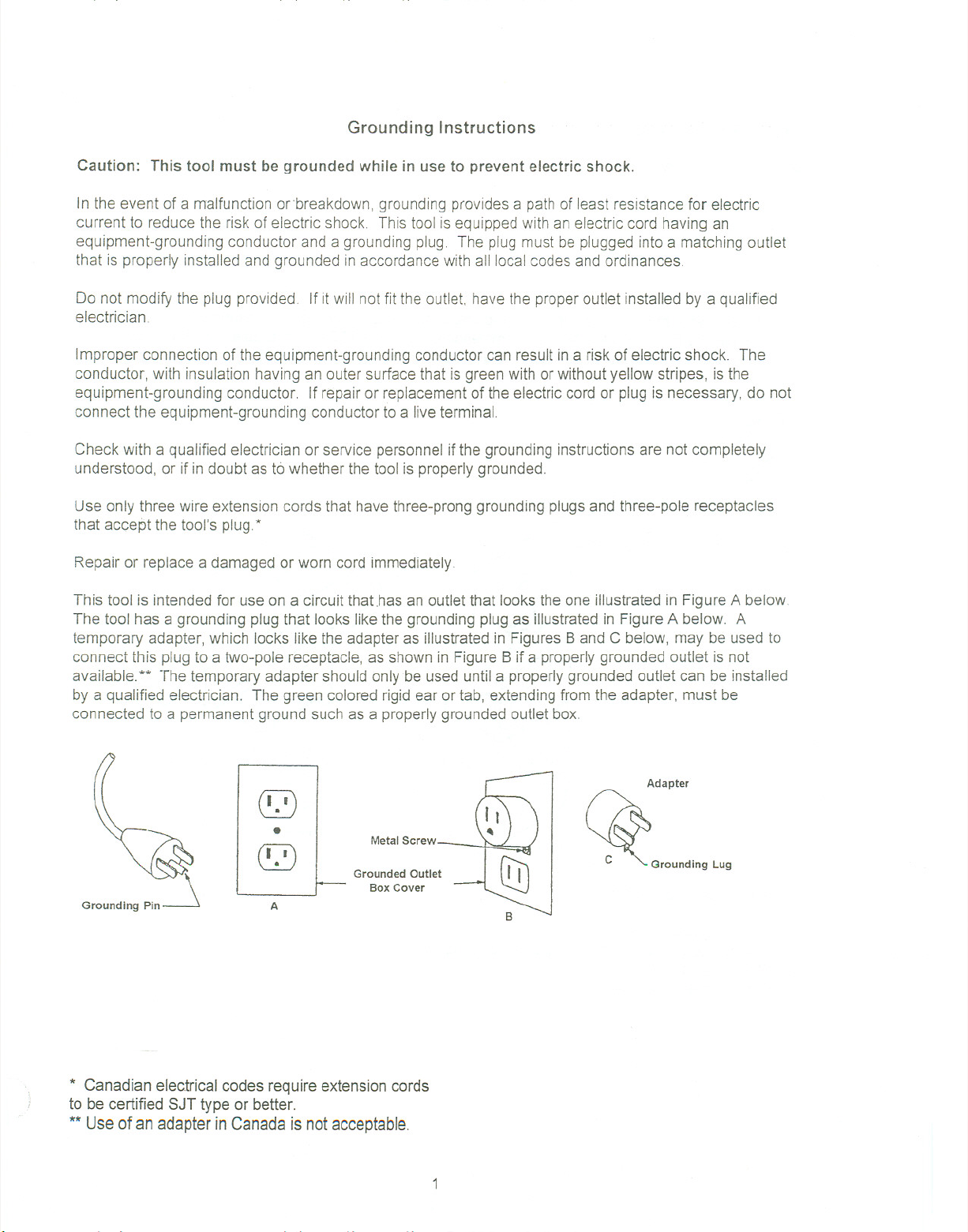
Grounding Instructions
Caution: This tool must be grounded while in use to prevent electric shock.
Inthe event of a malfunctionor breakdown.groundingprovidesa path of least resistancefor electric
current to reduce the risk of electric shock Thistool is equippedwith an electric cord having an
equipment-groundingconductor and a grounding plug. The plug must be pluggedinto a matchingoutlet
that is properly installedand grounded in accordancewith all localcodes andordinances.
Do not modify the plug provided. If it will not fit the outlet. have the proper outlet installed by a qualified
electrician
Improper connection of the equipment-groundingconductorcan result ina risk of electric shock. The
conductor, with insulation having an outer surfacethat is greenwith or withoutyellow stripes, isthe
equipment-groundingconductor. If repairor replacementof the electriccord or plug is necessary, do not
connect the equipment-groundingconductorto a live terminal
Check with a qualifiedelectrician or service personnelif the groundinginstructionsare not completely
understood, or if in doubt asto whether the tool is properlygrounded.
Use only three wire extension cords that have three-prong grounding plugs and three-pole receptacles
that accept the tool's plug *
Repair or replace a damaged or worn cord immediately
This tool is intended for use on a circuit that.hasan outletthat looks theone illustrated in FigureA below
The tool has a groundingplug that lookslike the grounding plugas illustratedin FigureA below. A
temporary adapter, which locks likethe adapter as illustrated in FiguresBand C below, may be usedto
connect this plugto a two-pole receptacle,as shownin Figure B if a properlygrounded outlet is not
available.** The temporaryadapter should only be used until a properlygrounded outlet can be installed
by a qualified electrician. The green colored rigidear ortab, extendingfrom the adapter, must be
connected to a permanentground such as a properlygroundedoutlet box.
Adapter
(!2)
.
~
A
Metal Screw
Grounded Outlet
Box Cover
~°'0"0';0' Lu,
* Canadian electrical codes requireextension cords
to be certified SJT type or better.
** Use of an adapter in Canada is not acceptable.
Page 6

On-Off Switch Padlock
Model No. BP-1, Stock No. 709736
To safeguard your machinefrom unauthorizedoperationand to avoid accidentalstarting byyoung
children, the use of a padlock is highlyrecommended. JET model BP-1 is availablefrom your local
authorized JET distributor or by callingJET Equipment& Tools at 800-274-6848.
To lock out an on-off switch
1. Open the padlock. See Fig. A
2. Insert through holes in the start button. See Fig. B
3. Close the padlock.
4. Place the key in a safe place.
-"--", ,,,,~-'--~-'--'--"--'"---'-'---'-'''-'''
....
'"
~ ~.~
2
Page 7

Specifications JWL-1236
Stock Number. """'" """""""""""" "'"'''' 708352
SwingOverBed """""""""""""""''''''''''''''''''''''''''''''''''''''''''''''' , 6"
Swing Over Tool Rest Base ... .,.,. , ,... .,..,.,. ...,..., , ", ,.,.,..., 4-3/8"
Distance Between Centers ""..,"""""",,, "'"'''''''''''''''''''''''''''''''''''''''''''' 35"
Speeds (RPM) '"'''''''' ... .. "''''''''''''''''''''''''''''''''''''''..'' '' 550-3000
Spindle Nose 1" x 8 T.P.I.
Hole through Spindle , , ,""""'''''''''''''''''''''''''''''''''''''''' , 3/8"
Headstock Taper , , , " MT-2
Tailstock Taper '"'' . """"' , MT-2
Ram Travel 2-1/4"
Spindle Center to Floor (approx.) """'"'''''''''''''''''''''''''''''''''''''''''''''''''''''''''''''''''''''''''''''''''''''''' 41"
Overall Dimensions
Motor " " 3/4 HP, 1Ph.
"""'''''' """"'''''''''''''''''''''''''''''''''' '"'''''''''' """""'''''''''''''''''''''''''''''''''''''''''' 115VOnly
Net Weight (approx.) '''''''''' " 183 Lbs.
Shipping Weight (approx.) '"'''''''''''''''''''''''''''''''''' 190Lbs.
The specifications in this manual are givenas general informationand are not binding. JET Equipment
and Tools reserves the rightto effect, at any timeand without prior notice,changes or alterations to parts,
fittings, and accessory equipment deemed necessaryfor any reasonwhatsoever.
"""""""""'''''''''''''''''''''''''''''''''''''''''''''' 44"H x 17"Wx 60"L
Table of Contents
Grounding Instructions ""'''''''' ""'"'''''''''' 1
On-Off Switch Padlock """'''''''''''''''''''''''''''' 2
Specifications 3
Table of Contents 3
Uncrating and Clean-Up ...4
ContentsofShippingCarton , 4
Tools Required for Assembly 4
Assembly .5-6
Controls 6-7
Nomenclature and Use """'..". 7
Adjusting Tool Rest 7
Operation ... ... ... 8-11
Parts Breakdown 12
Parts List 13-14
Electrical Schematic ...... .15
3
Page 8

Uncrating and Clean-Up
Note: Uncrating and assembly will require two
people due to the machines size and weight.
1.
Finish removing contents from the shipping
crate. Be sure to check crate thoroughly for
any parts not found on initial unpacking.
2.
Inspect contents for shipping damage and
report any damage to your distributor.
3.
Clean all protected parts with kerosene. Donot
use gasoline, paint thinner,or anyother
cellulose-basedsolvent. These will damage
paintedsurfaces and melt plastic.
Contents of Shipping Carton:
1 - Lathe bed wi motor and tailstock
1 - Tool rest wi extension
- Stand legs
4
2
- Long stand braces
-Short stand braces
2
-Stand tops
2
1 - Bed extension
1 - Face plate
1 - Drift rod
1 - Live center
1 - Spur center
2 - Index pins
1 - Face shield
1 - Hardware package (nuts, bolts, etc.)
1 - Operator's manual
1 - Warranty card
Tools Required for Assembly
NO.1 cross point screwdriver
NO.1 flat bladescrewdriver
Hex wrench set
Adjustablewrench or combinationwrench set
Use of sockets and a ratchet will speed stand
assembly but are not required.
- _.-_.'.
".- -- -'--"-- - --.,-- - - - .- 1
4
Page 9

Assembly
Note:
stand before tightening all nuts. Hand tighten only
during this part of the assembly'process
1
2.
3.
4.
Assemble stand completely and mount bed to
Attach a stand top (A, Fig. 1) to a stand leg (8,
Fig. 1) with three 5/16" x 1" carriage bolts (C,
Fig. 1), three 5/16" flat washers (D, Fig. 1),
three 5/16" lock washers (E, Fig. 1), and three
5/16" hex nuts (F, Fig. 1) Stand top must be
placed inside stand leg.
Attach second stand leg to previous assembly
in the same manner.
Repeat these steps with the remaining two
stand legs and stand top.
Join the two leg assemblies by attaching long
braces (G, Fig. 1) to each leg and fastening
with eight 5/16" x 1"carriage bolts (C, Fig. 1),
eight 5/16" flat washers (D, fig. 1), eight 5/16"
lock washers(E, Fig. 1) and eight 5/16" hex
nuts (F, Fig. 1). Remember
to hand tighten
only at this time.
A
FIG-1
5.
Attach short braces (H, Fig. 1)to each end of
the stand usingfour 5/16"x 1"carriage bolts
(C, Fig, 1),four 5/16" flat washers (D, Fig. 1),
four 5/16" lockwashers (E, Fig. 1), andfour
5/16" hex nuts (F, Fig. 1)
6.
Place assembled stand in approximate final
location that is solid and level.
7.
With the helpof a second person, carefully lift
bed up and onto stand.
Note: Be sure to place headstockend on the
stand end with the switch.
Note: Beforesetting bed assembly down on the
stand top, run motor cord through the hole in
the stand top.
5
Page 10

8.
Align holes on bed with those in the stand top
and fasten with eight hex socket cap screws
(5/16"x1") , eight lock washers (5/16"), and
eight nuts (5/16") supplied. Note: Two larger
hex socket cap screws and washers will be
used later to attach the bed extension to the
bed.
9.
Tighten eight hex socket cap screws with a hex
wrench.
1O. Tightenall stand hardware making sure it is
stable on the shop floor.
11. Attach bed extensionto bed usingtwo hex
socket cap screws (3/8"x1") andtwo lock
washers (3/8") supplied.
...-.-----------------------
12. Insert index plunger(A, Fig.2) intothe base of
the headstock (B, Fig.2) and tighten.
13. \ttach the headstocklock handle (A, Fig.3) to
the head stock lock shaft (B, Fig.3) with one
spring (C, Fig. 3) andone hex socket cap
screw (0, Fig.3).
14. Attach the tailstock handleto theto the tailstock
handwheelandtighten.
15. Connect the motorcord plugto the switch plug.
Controls
Speed Selector (A, Fig. 4) - selects one of six
available speeds. Select desired speed by pulling
handle out from headstock and turning to left or right.
Release handle and it will engage detent for that
speed. Caution: Never change speeds without
motor running. Damage to the variable speed
pulleys may result.
Headstock Lock (B, Fig.4)-locks headstockin a
fixed position. Tighten clockwiseto lock. Loosen
counterclockwiseto unlock. Caution: always
operate lathewith the headstockin the locked
position.
FIG-2
~A
B -~c --'
~D--
FIG-3
Detent Release(C, Fig.4) - pullout and holdto
swivel headstock. Releaseto engagedetentsat 90
or 180 degrees.
,- ._~- .--.
..- _. ..~- - ~_. -- ,,-
FIG-4
6
Page 11

-------
./
Tailstock Handwheel (A, Fig. 5) - turn clockwise to
move tailstock spindle forward. Turn counter-
clockwise to retract tailstock spindle.
Tailstock Spindle Lock (B, Fig: 5) - locks tailstock
spindle. Release to adjust handwheel.
Tailstock Lock (C, Fig. 5) - locks tailstock in
position on the bed. Release to move tailstock
assembly closer to or farther from the headstock.
Nomenclature and Use
Spur Center (A, Fig. 6) - locks into headstock and
holds the workpiece during spindle turning.
Index Pins (B, Fig. 6) - used to install and remove
spur center and face plate.
FIG-5
B
c
I
fl
Face plate (C, Fig. 6) - attaches to headstock and is
used in face plate turning operations.
"-- Drift Rod (D, Fig. 6) - fits into the tailstocktO,remove
\ I the livecenter and into the headstockto removethe
' / livecenter..
Tool Rest (Fig. 7) - attaches to any locationon the
bed or bed extension. Usedto steady cuttingtool
during spindleturning or face plate operations.
Adjusting Tool Rest
Position the tool rest as close to the work piece as
possible. It should be 1/8" above the centerline.
Position the tool rest base on the bed or bed
extension by releasing the lock handle (A, Fig. 7)
and sliding onto the desired position. Tighten handle
(A, Fig. 7) to lock. Adjust the height of the tool rest
by loosening handle (B, Fig. 7) and raising ,arm (C,
Fig. 7).
Shouldadjustment of the tool rest clampingdevice
become necessary, simply turn base over and adjust
~-, largenut(A,Fig.8).
.- .--'--' _w- ---
d-
fA
FIG-6
B
FIG-?
-,...,---
7
FIG.8
Page 12

Operation
Lt,WARNING!
Use supplied face shield or similar protection
during all operations! Failure to comply may
cause serious injury!
Befere attempting work on regular stock, use scrap
material to get a feel for the machine.
Lathe Tools
Most turning is accomplished with special
woodworking chisels. They are available individually
or in sets. JET's wood turning chisel set ( optional
accessory - stock No. 709008) contains eight of the
most popular types of chisels:
5/16", 1/2", and 1" Gouge - a round nose,hollow
chisel for roughingand cove cutting
1/2" and 1" Skew -a double ground, flat, andend
ground to an angle used for smoothingcylindersand
cutting shoulders, beads, v-grooves, etc.
1/2" Diamond Point and 1/2" Round Nose - used
where their shape fits the contour of the work.
1/2" Parting Tool - double-groundchisel usedfor
cutting-off, straight incisions, and sizingcuts to any
diameter.
Spindle Turning
The majorityof turning on a wood lathewill be
betweencenters, or spindle turning.
Centering the Work
Preparation of the stock for spindle turning starts
with finding the center of the work piece. The most
common method is the diagonal method. Draw two
lines to attach opposite corners on each end of the
workpiece (Fig. 9). The intersection of these two
lines is the center. Mark both ends of the stock.
Mark the center of each end with a punch awl for
softer wood or drill each end approximately 1/8"
depth for harder woods. Place the spur center on
one end and seat it by striking with a mallet. Hold
the center and work piece together and prepare to
mount between the spindles.
FIG-9
8
Page 13

Mounting the Work
Move the tailstockto approximately 1 to 1-1/2" from
the end of the work pieceand lock in position. Turn
the tailstock handwheel untilthe center makes
contact with the work piece. Continueto turn the
hand wheel and slowly rotatethe work pieceby
hand. After the work piecebecomes difficult to turn
by hand, reverse the handwheel approximatelyone
quarter turn and lockthe tailstock spindle (Fig. 10)
Adjusting the Tool Rest
-'" -
Position the tool rest approximately 1/8" away from
the work piece and 1/8" above the work centerline.
After some experience has been gained, this position
can be varied slightly to suit the operation.
Position of Hands
/-"
There is no "proper" positionfor the handswhen
using chisels. Most beginners begin by usingthe
) palm-down grip (Fig. 11)for bettercontrol and switch
later to the palm-up position(Fig. 12) for better
manipulation. Inthe palm-downposition,the little
finger or heel of the hand acts as a guide alongthe
tool rest. The first finger acts as a guidewhen using
the palm-up method.
Roughing a Cylinder
Use a large gouge and run the lathe at a slow speed
to rough-off the sharp corners of the work. Beginthe
cut 2 to 3 inches from the tailstock and work toward
and off the tailstock end. Continue by cuttingthe
next 2 to 3 inches left of the first cut, preferably
working toward the tailstock end. This method of
always working toward the tailstock is preferred
because it throws the chips clear of the operator. Do
not rough cut by taking one long pass at the work
piece and do not start cuts at either end ofthe work
piece. This has a tendency to tear long sliversfrom
the work piece. Rollthe gouge over slightly in the
direction of the cut for best results. Once a
cylindrical form has started to take shape, step up
the speed one or two stops.
FIG -10
FIG -11
FIG -12
,-.- ,-- -- ..-- ._--
9
Page 14

Smoothing a Cylinder
Use a largeskew chisel with the cutting point near
the center of the chisel and high up on the work
piece. Support the chisel on the tool rest at all times.
To locate the proper cutting position, placethe chisel
flat against the work piece with the skewwell over
the area to be cut. Pull back slowly on thechisel
until it bites into the wood. Raising the handlewill
increase the depth of cut; lowering the handlewill
decrease the depth of cut.
Using the Parting Tool
The parting tool is a scraping tool and is simply
pushed into the work piece.. A better cutting action is
obtained by starting the cut with the handle low and
gradually raising it as the cut gets deeper. If the cut
is over 3/8" deep, a clearance cut should be made
along side the first cut to avoid burning the chisel
point.
Face Plate Turning
Work that cannot be turned between centersmustbe
attached to and turned on a face plate. All work
should be cut slightly oversized prior to mountingon
the face plate to prevent heavy roughingcuts during
turning.
Mount the work piece directly to the face plate using
four wood screws from the back. Be careful to use
screws short enough not to interfere with the cutting
process but long enough to hold the work piece
securely to the face plate. If screws will interfere
with the cutting process, the work piece can be
screwed to a backing block and the backing block
screwed to the face plate. If screw mounting is not
allowed at all, the work may be glued to a backing
block and the backing block screwed to the face
plate. A piece of paper in the glue joint will prevent
damaging the wood when separated later.
Remove the spur center from the headstock spindle
by inserting the drift pin into the opening in the
headstock and pushing the spur center out. Mount
the face plate with the workpiece already attached
onto the threaded portion of the spindle and hand
tighten.
the headstock spindle facing the tailstock (Fig. 13).
For larger work pieces, the head stock will have to
Note: pieces up to 12" may be turned with
FIG -13
10
Page 15

~ be turned 90 degrees,the tool rest extensionadded
, to the tool rest, and the tool rest moved out to the
bed extension (Fig. 14).
For face plate turning, the tool rest is set
approximately 1/8" from the work piece and slightly
lower than centerline. The chisel must be held on
the left half of the tool rest so that the rotation of the
work piece keeps the chisel against the tool rest.
Attempts at cutting from the right side of the rest may
cause the chisel to be ripped from the operator's
hand.
FIG-14
~
",--
J
~~
~ ~"' - .---.-
--- --
11
--
-- -- --- '--'--
Page 16

--
N
57-\
~
Page 17

~-
Parts List for the JWL-1236 Woodworking Lathe
Index Part
No. No.
Description
1 .JWL1236-01W Headstock 1
2 JWL1236-02 SpurCenter 1
3 JWL1236-03 Face Plate. 1
4 . .JWL1236-04 ""'" Spindle """'"'''''''''' 1
5... ..JWL 1236-05... Key 4x4x85 """""""""'''' 1
6. ...BB-6205ZZ BallBearing 1
7 BB-6205ZZ Ball Bearing ... 1
8 .JWL1236-08 Spring 1
9 JWL1236-09 ShiftingLeverBracket 1
10 BB-6006Z"""""""'''''''''''' BallBearing 1
11 JWL1236-11 C-Clip S-25 1
12 JWL1236-12 SpindlePulley(right) 1
13 VB-M23 V-Belt 1
14 JWL1236-14 Spindle Pulley(left)"'''''''''''''''''''''''''''''''''''''''' 1
15.. JWL1236-15 C-Clip S-24 1
16 JWL1236-16 Drift Rod 1
17 .JWL1236-17 Lock NuL 1/2 2
.~-
,~
18 JWL1236-18 Clamp (left) 1
19 TS-0011031 Hex.HeadBoiL 5/16x3/4 2
19-1 TS-0720081 LockWasher..... 5/16 2
20 JWL1236-20 Rack 1
21 JWL1236-21 SpeedSelectorAssembly 1
21-1 JWL1236-21-1 PanHeadScrew 2
21-2 JWL1236-21-2 SetScrew 5/16 1
22 JWL1236-22 Clamp(right) : 1
23 JWL1236-23 Hex Head Screw 1
24 JWL1236-24 HeadstockLock 1
24-1 JWL1236-24-1 HeadstockLock Handle 1
24-2 JWL1236-24-2 Spring 1
24-3 JWL1236-24-3 Screw 1
25 JWL1236-25A lndex Tool 1
25-1 JWL1236-25-1 IndexTool 1
26 JWL 1236-26 C-Clip : S-16 1
27 JWL1236-27 Sleeve 1
28 JWL1236-28 Spring 1
29 JWL1236-29 Motor Pulley(right) 1
30 JWL1236-30 , MotorPulley(left) 1
31 JWL1236-31 PanHeadScrew 3/16x3/8 4
32 JWL1236-32 Key 4x4x85 1
33.. JWL1236-33 MotorwI Motor Cord 1
JWL1236-33A MotorwI Motor Cord (afterserial#305000) 1
33-1 JWL1236-33-1 Nameplate 1
34 JWL1236-34W MotorCover 1
JWL1236-34A MotorCover (after serial#305000) 1
35 JWl1236-35 Index Plunger 1
36,:::-; JWL1236-36=.,;,:,,:,,;, "C.'".. . Tool Rest-:~,,:,:~.=,,,,,,,,=..,.,.,.,.=..,,,,,,=:-;,=...,,n-,.,.,.~.-,.,.,,~.,,,,,",,..,,,",..,...""..=."",.,',,,,,-...~..- - - ..- -
JWL1236-36A Tool Rest (afterserial #205000) 1" 1
Size
Qty.
13
Page 18

- --
37. . ..JWL 1236-37 Handle "" ,... .""'"'' . .. ... 3
38. . ..JWL 1236-38 Tool Rest Extension '''''''''' 1
...JWL1236-38A Tool RestExtension(afterserial #205000) ""' ".. 1
39 JWL1236-39 Tool RestBody : 1
JWL 1236-39A Tool Rest Body (after serial #205000) 1" 1
40 JWL 1236-40 Eccentric Rod 1
41 JWL 1236-26 C-Clip . . .. S-16 """"'"'''''' 2
42.. JWL 1236-42 BoiL . """''''''''''''''''' " .'.. 1
42-1 JWL 1236-42-1 ..""'" ... .. Bol1 . "" , '''''''''''''''''' """'"'''''''''''''''''''''''' 1
43 JWL 1236-43 ... ... Clamp ... ".. 2
44 .TS-0640141 Nut 3/4 2
45 .JWL 1236-45 Live Center """''''''''''''''''''''''' ""'''''' ,..
46
., JWL1236-46 Tail Spindle ,.. 1
47 JWL 1236-47 Tailstock Screw "'"'''''''''''''''''''''''' 1
48 .., JWL 1236-48W ""'"'''' Tailstock """""""'"'''''''''''''''''''''''''''' ..'"'' 1
48-1 JWL1236-48-1 C-Ring ...S-16 1
48-2 JWL1236-48-2 Set Screw"""""'''''''''''''''''''''''''''''''''''''''''''''' 1
49 ..JWL 1236-49 "'" """""" Handwheel .""""""" 1
50 JWl1236-50 Tailstock Lock Handle 1
51' JWL 1236-51 Handle Stop "".., 1
52 JWL 1236-52W... ',""" Bed Extension """'''''''''''''''''''''''''''' 1
53... TS-0209051 .. Hex Socket Cap Screw ...""" 3/8x1 2
53-1 TS-0720091 Lock Washer 3/8 2
54 ...JWL 1236-54W... Stand Leg (left rear) """""" ... ..., 1
54-1 .....JWL 1236-54-1 W Stand Leg (right front)... 1
54-2 JWL 1236-54-2W Stand Leg (left front
-switch) 1
54-2A ..JWL 1236-54-2AW.. Stand Leg (right rear) 1
54-3 JWL 1236-54-3W. Stand Top '''''''''''''''''''''''''''''''''''''''''''''''''''''''' . 2
54-4. ...JWL 1236-54-4W. ... Long Brace """""'" .. 2
54-5... .JWL 1236-54-5W .."" Short Brace ' '"'''''''' """'''''''''''''''''''''' ... """"""'''''''''''''''''' 2
55 JWL1236-55W... """" Bed """ " 1
56 TS-0208061 ""'" . Hex Socket Cap Screw 5/16 x 11/4" 8
57 .JWL 1236-57. ... """ Switch (serial
#6105922andlower) 1
.JWL 1236-57 A """'" Switch (serial #6115923 and higher) 1
JWL 1236-57B... Switch Assembly CP (serial #6105922 and lower) 1
... JWL1236-57C. '" SwitchAssemblyCP (serial#6115923 and higher) 1
57-1 JWL 1236-57-1 Switch Box .."'''''''''''''' ,. 1
58 .JWL 1236-58. " Screw M4x24 2
59 ..."'" JWL 1236-59 "" Screw """'"'''''''''''''''''''''''' 3/16x3/8 2
59-1 JWL 1236-59-1 Key Washer " '''''''''''''''''''''''''''''''''' 2
59-2 JWL 1236-59-2 Nut """""'"'''''''''''''''''''''''''''''''''''''''''''''''''''''' 3/16 2
60 TS-0152011 Carriage Bolt... 5/16x1 24
61 ... .. TS-0680031 Washer "".." 5/16 24
62 ..."... TS-0561 021 '"'''''''''''' Nut 5/16 24
63 ... . ..JWL 1236-63 Power Cord... .." "'"'''''''''''''''''''''' 1
63-1 . ..JWL 1236-63-1 Power Cord (switch to motor - serial #6105922 and lower) 1
'" ...JWL 1236-63-1A """'''''''''' Power Cord (switch to motor - serial #6115923 and higher) 1
63-2 JWL 1236-63-2 : Motor Cord (serial #6105922 and lower) 1
JWL 1236-63-2A Motor Cord (serial #6115923 and higher) 1
64 J\iVL1236-64 ,... , Label 1
65 JWL 1236-65" """, Warning Label. 1
66 ..JWL 1236~66 ,,, Speed Label
67 ... TS-OnOO81 LockWasher 5/16 32
JWL 1236-C '''''''' Capacitor (not shown-100MFD, 125VAC) 1
1
1
14
Page 19

Electrical Schematic
~
BLACK
'w'HITE
GREEN
'..
T
GROUND
BLACK
GREEN
--
--- ---------.
_.e__-
15
----
-----
---
Page 20

 Loading...