


This .pdf document is bookmarked
Operating Instructions and Parts Manual
Variable Speed Turret Mill
Model JTM-1050VS2
JET
427 New Sanford Road
LaVergne, Tennessee 37086 M-691050
Ph.: 800-274-6848 Edition 2 11/2019
www.jettools.com Copyright © 2018 JET

1.0 IMPORTANT SAFETY
INSTRUCTIONS
1. Read and understand the entire owner's
manual before attempting assembly or
operation.
2. Read and understand the warnings posted on
the machine and in this manual. Failure to
comply with all of these warnings may cause
serious injury.
3. Replace the warning labels if they become
obscured or removed.
4. This machine is designed and intended for use
by properly trained and experienced personnel
only. If you are not familiar with the proper and
safe operation of milling machines, do not use
until proper training and knowledge have been
obtained.
5. Do not use this milling machine for other than
its intended use. If used for other purposes,
JET disclaims any real or implied warranty and
holds itself harmless from any injury that may
result from that use.
6. Always wear approved safety glasses/face
shields while using this machine. Everyday
eyeglasses only have impact resistant lenses;
they are not safety glasses.
7. Before operating this machine, remove tie,
rings, watches and other jewelry, and roll
sleeves up past the elbows. Remove all loose
clothing and confine long hair. Non-slip
footwear or anti-skid floor strips are
recommended. Do not wear gloves.
8. Wear ear protectors (plugs or muffs) during
extended periods of operation.
9. Do not operate this machine while tired or
under the influence of drugs, alcohol or any
medication.
10. Make certain the switch is in the OFF position
before connecting the machine to the power
supply.
11. Make certain the machine is properly
grounded.
12. Make all machine adjustments or maintenance
with the machine unplugged from the power
source.
13. Remove adjusting keys and wrenches. Form a
habit of checking to see that keys and
adjusting wrenches are removed from the
machine before turning it on.
14. Keep safety guards in place at all times when
the machine is in use. If removed for
maintenance purposes, use extreme caution
and replace the guards immediately after
completion of maintenance.
15. Keep hands away from all moving parts (belts,
cutters, gears, etc.)
16. Check damaged parts. Before further use of
the machine, a guard or other part that is
damaged should be carefully checked to
determine that it will operate properly and
perform its intended function. Check for
alignment of moving parts, binding of moving
parts, breakage of parts, mounting and any
other conditions that may affect its operation.
A guard or other part that is damaged should
be properly repaired or replaced.
17. Provide for adequate space surrounding work
area and non-glare, overhead lighting.
18. Keep the floor around the machine clean and
free of scrap material, oil and grease.
19. Some coolants used for machining contain
chemicals that may be hazardous to your
health if not use properly. Read and
understand all user information listed on the
coolant container and protect yourself
accordingly.
20. Keep visitors a safe distance from the work
area. Keep children away.
21. Make your workshop child proof with padlocks,
master switches or by removing starter keys.
22. Give your work undivided attention. Looking
around, carrying on a conversation and “horseplay” are careless acts that can result in
serious injury.
23. Maintain a balanced stance at all times so that
you do not fall into the blade or other moving
parts. Do not overreach or use excessive force
to perform any machine operation.
24. Use the right tool at the correct speed and
feed rate. Rotate spindle clockwise for righthand tools, counterclockwise for left-hand
tools. Do not force a tool or attachment to do a
job for which it was not designed. The right
tool will do the job better and more safely.
25. Use recommended accessories; improper
accessories may be hazardous.
26. Frequently clean this machine. Maintain tools
with care. Keep cutters sharp and clean for the
best and safest performance. Follow
instructions for lubricating and changing
accessories.
27. Turn off the machine before cleaning. Use a
brush to remove chips or debris — do not use
bare hands.
2

28. Do not stand on the machine. Serious injury
could occur if the machine tips over.
29. Never leave the machine running unattended.
Turn the power off and do not leave the
machine until it comes to a complete stop.
30. Remove loose items and unnecessary work
pieces from the area before starting the
machine.
31. Don’t use in dangerous environment. Don’t
use power tools in damp or wet location, or
expose them to rain. Keep work area well
lighted.
32. Some coolants used for machining contain
chemicals that may be hazardous to your
health if not used properly. Read and
understand all user information listed on the
coolant container and protect yourself
accordingly.
WARNING: This product can expose you to
chemicals including lead and cadmium which
are known to the State of California to cause
cancer and birth defects or other reproductive
harm, and phthalates which are known to the
State of California to cause birth defects or
other reproductive harm. For more information
go to http://www.p65warnings.ca.gov.
WARNING: Some dust, fumes and gases
created by power sanding, sawing, grinding,
drilling, welding and other construction activities
contain chemicals known to the State of
California to cause cancer and birth defects or
other reproductive harm. Some examples of
these chemicals are:
lead from lead based paint
crystalline silica from bricks, cement and
other masonry products
arsenic and chromium from chemically
treated lumber
Your risk of exposure varies, depending on how
often you do this type of work. To reduce your
exposure to these chemicals, work in a wellventilated area and work with approved safety
equipment, such as dust masks that are
specifically designed to filter out microscopic
particles. For more information go to
http://www.p65warnings.ca.gov/ and http://
www.p65warnings.ca.gov/wood.
Familiarize yourself with the following safety notices used in this manual:
This means that if precautions are not heeded, it may result in minor injury and/or possible
machine damage.
This means that if precautions are not heeded, it may result in serious, or possibly even fatal,
injury.
3

2.0 Table of contents
Section Page
1.0 IMPORTANT SAFETY INSTRUCTIONS ....................................................................................................... 2
2.0 Table of contents ............................................................................................................................................ 4
3.0 About this manual .......................................................................................................................................... 5
4.0 Specifications ................................................................................................................................................. 5
5.0 JTM-1050VS2 Machine dimensions .............................................................................................................. 7
6.0 JTM-1050VS2 Features ................................................................................................................................. 8
7.0 Set-up and assembly ..................................................................................................................................... 9
7.1 Contents of shipping container ................................................................................................................... 9
7.2 Site preparation .......................................................................................................................................... 9
7.3 Lifting the mill ............................................................................................................................................. 9
7.4 Completing assembly ............................................................................................................................... 10
7.5 Lubrication ................................................................................................................................................ 11
8.0 Electrical Connections .................................................................................................................................. 11
8.1 Voltage conversion ................................................................................................................................... 11
8.2 Wire Sizes ................................................................................................................................................ 11
9.0 Operation ..................................................................................................................................................... 11
9.1 Precautions .............................................................................................................................................. 11
9.2 Operating controls .................................................................................................................................... 12
9.3 Control positions for milling and drilling operations .................................................................................. 13
10.0 Adjustments ............................................................................................................................................... 14
10.1 Drawbar operation - changing tooling .................................................................................................... 14
10.2 Clamping workpiece to table .................................................................................................................. 14
10.3 Changing speed range ........................................................................................................................... 14
10.4 Manual feed ............................................................................................................................................ 14
10.5 Automatic feed ....................................................................................................................................... 15
10.6 Mill head – left/right rotation ................................................................................................................... 15
10.7 Mill head – front/back tilt ......................................................................................................................... 16
10.8 Ram movement ...................................................................................................................................... 16
10.9 Table and Knee Movement .................................................................................................................... 17
10.10 Feed Trip Adjustment ........................................................................................................................... 17
11.0 User-maintenance ...................................................................................................................................... 18
11.1 General maintenance ............................................................................................................................. 18
11.2 Lubrication .............................................................................................................................................. 18
11.3 Gib adjustments ..................................................................................................................................... 18
11.4 Leadscrew backlash adjustment ............................................................................................................ 19
12.0 Recommended speed for mill and drill operations ..................................................................................... 20
13.0 Replacement Parts ..................................................................................................................................... 20
13.1.1 JTM-1050VS2 Upper Head Assembly – Exploded View ..................................................................... 21
13.1.2 JTM-1050VS2 Upper Head Assembly – Parts List ............................................................................. 22
13.2.1 JTM-1050VS2 Lower Head Assembly – Exploded View ..................................................................... 25
13.2.2 JTM-1050VS2 Lower Head Assembly – Parts List ............................................................................. 26
13.3.1 JTM-1050VS2 Column and Base Assembly – Exploded View ........................................................... 29
13.3.2 JTM-1050VS2 Column and Base Assembly – Parts List .................................................................... 30
13.4.1 JTM-1050VS2 Table Leadscrew Assembly – Exploded View ............................................................. 32
13.4.2 JTM-1050VS2 Table Leadscrew Assembly – Parts List ..................................................................... 32
13.5.1 JTM-1050VS2 Spindle Guard Assembly – Exploded View ................................................................. 33
13.5.2 JTM-1050VS2 Spindle Guard Assembly – Parts List .......................................................................... 33
13.6.1 JTM-1050VS2 One-Shot Lubrication System – Exploded View .......................................................... 34
13.6.2 JTM-1050VS2 One-Shot Lubrication System – Parts List .................................................................. 34
13.6.1 JTM-1050VS2 Work Lamp & Connector Box – Exploded View .......................................................... 35
13.6.2 JTM-1050VS2 Work Lamp & Connector Box – Parts List ................................................................... 35
14.0 Electrical connections for JTM-1050VS2 ................................................................................................... 36
15.0 Warranty and service ................................................................................................................................. 37

3.0 About this manual
This manual is provided by JET covering the safe operation and maintenance procedures for a JET Model
JTM-1050VS2 Turret Mill. This manual contains instructions on installation, safety precautions, general
operating procedures, maintenance instructions and parts breakdown. Your machine has been designed and
constructed to provide consistent, long-term operation if used in accordance with the instructions set forth in
this document.
This manual is intended to familiarize you with the technical aspects of this milling machine. It is not, nor was it
intended to be, a training manual. Do not operate this machine until appropriate training and knowledge have
been acquired.
If there are questions or comments, please contact your local supplier or JET. JET can also be reached at our
web site: www.jettools.com.
Retain this manual for future reference. If the machine transfers ownership, the manual should accompany it.
Read and understand the entire contents of this manual before attempting assembly
or operation. Failure to comply may cause serious injury.
Register your product using the mail-in card provided, or register online:
http://www.jettools.com/us/en/service-and-support/product-registration/
4.0 Specifications
Table 1
Model number
Stock number
Motor and Electricals
Motor type Totally enclosed, fan cooled
Horsepower 3 HP (2.25 kW)
Motor phase 3 PH
Motor voltage 230/460V (prewired 230V)
Cycle 60 Hz
Listed FLA (full load amps) 8.2 / 4.1 A
Motor speed 1720 RPM
Power transfer Belt and gear
On/off switch Rotary, reversible
LED lamp 110V, separate power cord
Sound emission 1
Head and spindle
Spindle taper R8
Diameter of quill 3-3/8 in. (85.72 mm)
Number of spindle speeds Variable within specified ranges
Range of spindle speeds 60-500, 500-4200 RPM
Downfeeds per revolution of spindle 0.0015, 0.003, 0.008 in/rev. (0.038, 0.076, 0.203 mm/rev.)
Spindle travel 5 in. (127 mm)
Head movement – left and right 90 deg.
Head movement – fore and aft 45 deg.
1
The specified values are emission levels and are not necessarily to be seen as safe operating levels. As workplace
conditions vary, this information is intended to allow the user to make a better estimation of the hazards and risks
involved only.
Without load 75 dB, at 3 ft. from machine
With load 80-85 dB, at 3 ft. from machine
JTM-1050VS2
691050
5

Head and spindle (cont.)
Distance spindle nose to table
Distance spindle center to column
Collet capacity 1/8 to 5/8 in.
Ram travel, maximum
Micrometer adjusting nut travel 0.025 in. (0.635 mm) per one rotation
Table and column
Table size
Longitudinal table travel, maximum 29-7/8 (760 mm), 34-1/4 in. (870 mm) over saddle
Cross table travel, maximum
Number of T-slots 3
T-slot width 5/8 in. (16 mm)
T-slot centers
Table load, maximum
Knee travel, maximum
Column width
Saddle width
Dimensions
Overall dimensions, assembled, LxWxH 63 x 63 x 90 in. (1600 x 1600 x 2270 mm)
Weights
Net weight 2466 lbs. (1119 kg)
Shipping weight
The specifications in this manual were current at time of publication, but because of our policy of continuous
improvement, JET reserves the right to change specifications at any time and without prior notice, without incurring
obligations.
Maximum 20 in. (500 mm)
Minimum 3.26 in. (83 mm)
Maximum
Minimum
26-3/4 in. (681 mm) – ram flush at turret platform edge
27 in. (686 mm) – ram beyond turret platform edge
6.3 in. (160 mm) – ram flush at turret platform edge
2.75 in. (70 mm) – ram beyond turret platform edge
17.3 in. (440 mm) – ram flush at turret platform edge
21 in. (535 mm) – ram beyond turret platform edge
10 x 50 in. (254 x 1270 mm)
14-3/4 in. (375 mm)
2-1/2 in. (64 mm)
840 lbs. (381 kg)
16-1/8 in. (412 mm)
12 in. (300 mm)
20 in. (510 mm)
2598 lbs. (1178 kg)
6

5.0 JTM-1050VS2 Machine dimensions
Figure 5-1: machine dimensions
7

6.0 JTM-1050VS2 Features
1. 5HP Motor
2. Lifting ring
3. Ram
4. Ram lock bolt (x2)
5. Turret scale
6. Ram pinion
7. Machine I.D./Warning Label
8. Table longitudinal crank handle (x2)
9. Power connection box
10. Base
11. Strainer (x2) – for use with optional flood
coolant systems
12. Leveling screw (x4)
13. Elevating leadscrew
14. Knee
15. Crossfeed handle
16. Knee crank handle
Figure 6-1: Features
17. Pleated way cover
18. Table locking handle (x2)
19. Flat way cover
20. Column
21. Spindle, R8 taper
22. Head assembly (see sect. 9.2 for explanation
of controls)
23. Motor junction box
24. Saddle locking handle
25. One-shot lube system
26. Knee locking handle (x2)
27. LED Work Lamp
28. Spindle Guard
29. Leveling pad (x4)
30. Saddle
31. Turret lock bolt (x4)
32. Belt access cover (x2)
8

Read and understand entire
contents of this manual before attempting setup or operation. Failure to comply may cause
serious injury.
7.0 Set-up and assembly
Open shipping container and check for shipping
damage. Report any damage immediately to your
distributor and shipping agent. Do not discard any
shipping material until Turret Mill is assembled and
running properly.
Compare contents of your container with the
following parts list to make sure all parts are intact.
Missing parts, if any, should be reported to your
distributor. (Check machine first in case parts have
been preinstalled.)
If your mill is supplied with an optional Table
Powerfeed and/or DRO (digital read-out), be sure
to consult the separate instruction materials that
accompany them.
7.1 Contents of shipping container
1 Oil Can *
1 Elevating Crank Handle
1 Handwheel
1 Coarse Feed Handle
1 Lifting ring
1 Operator’s Manual
1 Product Registration Card
* parts with asterisk are also included in tool box
service kit JTM1050VS2-TB.
7.2 Site preparation
The mill must be placed on an even surface and
bolted to the floor. Anchor bolts of sufficient size
and length must be fastened to the floor according
to the mill’s footprint. See layout diagram in Figure
5-1.
The diagram shows maximum dimensions of the
Mill with table and ram fully extended to maximum
travel. When spotting the machine, leave room not
only for the machine itself, but also clearance for
the operator, for servicing the machine, and for any
unusual size of workpiece that might extend off the
machine’s table.
7.3 Lifting the mill
Figure 7-1: contents
1 Turret Mill (not shown)
1 Spindle Guard (not shown)
1 Flat Way Cover
1 Pleated Way Cover
1 Draw Bar
3 Table Adjustment Handles
1 Tool Box, containing:
4 Leveling pads
1 Hex Key Set (1.5-10mm) *
17/19mm Box Wrench *
1
1 Cross Point Screw Driver #2 *
1 Flat Blade Screw Driver #2 *
Finish removing the sides of the crate. Remove
any accessory items from machine table and
shipping pallet. Leave mill bolted to pallet until
ready to move to its final location.
The preferred method for lifting is with a hook
through the lifting ring screwed into the tapped hole
atop the ram:
1. Install provided lifting ring into tapped hole
atop ram. (Note: If your mill came with a topmounted DRO, remove DRO from hole to
install lifting ring. Reinstall DRO after machine
has been positioned.)
2. Check lifting ring on ram to be certain it is
tight.
3. Check tightness of lock hex nuts on ram (A,
Figure 7-2) to be certain ram is tightly
locked.
4. Remove fasteners holding mill to pallet.
An alternative method for lifting the mill is with a
sling. See Figure 7-2 for proper position of sling
under ram. Note position of ram and that table has
been moved against column. Tighten ram locking
nuts (A, Figure 7-2) before lifting.
5. Center an overhead crane or other suitable
overhead lifting device and sling arrangement
over the lifting ring.
IMPORTANT: This machine weighs nearly
2500 pounds. Be certain lifting arrangement is
new or in excellent condition and has a safety
factor that will account for age, difficulties in
lifting, etc.
9

When lifting using the ring, the machine may
tend to tip forward. If you wish, you can
minimize this tipping by rigging a support sling
over the front of the machine. Be careful when
doing this, to prevent the sling from damaging
any components on the front of the machine.
Be sure to steady the mill to prevent it from
spinning.
6. Lift machine off pallet no higher than
necessary to clear the hold-down hardware,
then slide pallet out of the way. Do NOT get
hands or feet underneath machine when
removing pallet.
7. Put machine base over the hold-down system
where the machine will be spotted.
8. When the mill is over its anchors, level the mill
using shims under the corners needing them.
The machinist’s level used for leveling should
be placed on the table. The table is the
reference surface for both side-to-side and
fore-and-aft leveling. Be certain you get it level
in BOTH directions.
Mill must be supported
equally under all four corners. Failure to
comply may cause the column to twist and
put a bind in the table ways.
9. When the machine is level, secure base to
anchoring system.
Figure 7-2: alternate lift - sling location
7.4 Completing assembly
Before attempting to raise mill
head, familiarize yourself with instructions in
sect. 10.6, for procedures to safely raise and
set up the mill head.
1. Loosen the four hexagonal nuts (see A, Figure
10-4) about one-quarter (1/4) turn each
counter-clockwise, just enough to allow
rotation of the head.
2. Apply upward pressure on motor by hand to
relieve pressure on worm mechanism, while
using supplied wrench to turn worm shaft (B,
Figure 10-4). Raise head to upright position.
3. Tighten nuts (A, Figure 10-4); not torqued at
this time, just snug. Before operating mill,
follow procedures in sect. 10.6 to verify angle
settings and properly tighten the four nuts.
4. Using mineral spirits or other cleaning solvent,
clean all of the rust proofing from where it may
have been applied. This is important; moving
the table or any other components before
removing the rust proofing will only put rust
proofing where you don’t want it. (Do not use
gasoline, paint thinner, or lacquer thinner these will damage painted surfaces.)
5. Lubricate exposed ways, then move each unit
(table and ram) to the opposite limit stop, and
clean and lubricate the newly exposed ways.
Loosen bolts to unlock ram and move it
forward and backward to the full length in
order to clean and lubricate.
6. Cover all machined surfaces with a film of light
machine tool oil to inhibit rust.
Some of the following steps may have already
been performed on the machine. If so, skip the
instructions related to those particular steps.
Otherwise, perform them in the order listed. Refer
to Figures 6-1 and 9-1 to help locate items.
7. Install handles on the table longitudinal and
cross-feed cranks. Use a wrench on the flats
to tighten them.
8. Remove any rust proofing from drawbar (O,
Figure 9-1) and its washer, and place drawbar
with washer installed into spindle center
through top of machine.
9. Slide fine feed handwheel (J, Figure 9-1) over
handwheel hub and push it back until its roll
pin engages hole in the hub and handwheel is
flush with hub surface.
10. Place coarse feed handle (F, Figure 9-1) on
feed shaft and tap it lightly until its roll pin
engages a hole in the hub. Tighten set screw
to secure handle.
10

11. Unwrap and clean elevating (knee) crank and
install it on its shaft. Secure it with washer and
socket cap screw preinstalled on shaft.
12. Install rubber way covers at front and behind
table.
7.5 Lubrication
Do not operate Mill before fully
lubricating it. Failure to comply may cause
damage to the machine.
Before operating mill, refer to sect. 11.2 for
lubricating instructions.
8.0 Electrical Connections
Electrical connections must
be made by a qualified electrician. This
machine must be properly grounded in
accordance with the National Electrical Code
and local codes and ordinances, to help
prevent electrical shock and possible fatal
injury.
The JTM-1050VS2 Mill is rated at 230/460V, 3phase and comes from the factory prewired at
230V. Confirm power at the site matches power
requirements of the Mill before connecting to power
source. The power source should be dedicated to
the Mill.
Remove junction box cover, and run main power
cable through box and attach the ground, followed
by power leads. Replace junction box cover.
Check for proper spindle rotation in the high speed
range. The spindle should rotate clockwise when
viewed from top of machine. If spindle rotates
counterclockwise, disconnect from power source,
and switch any two of the three power leads.
8.1 Voltage conversion
To change to 460V operation, remove junction box
cover on the motor, and change the wires
according to diagram found on inside of junction
box cover. A similar wiring diagram is found at the
back of this manual. If discrepancies arise, diagram
on machine takes precedence.
8.2 Wire Sizes
For circuits which are far away
from the electrical service box, the wire size
must be increased in order to deliver ample
voltage to the motor.
To minimize power losses and to prevent motor
overheating and burnout, the use of wire sizes for
branch circuits or electrical extension cords
according to Table 2 is recommended.
Conductor
Length
0 – 50 Ft. No. 14
50 – 100 Ft. No. 14
Over 100 Ft. No. 12
AWG Number
230/460 Volt Lines
Table 2
9.0 Operation
9.1 Precautions
Do not attempt to change spindle RPM while
motor is stopped. Only change spindle speeds
while motor is running.
Verify that spindle brake is released before
starting motor.
Rotate spindle by hand to facilitate meshing of
clutch and gears.
Do not use quill automatic feed at spindle
speeds above 3000 RPM.
It is recommended that the auto feed worm
gear be disengaged whenever auto feed is not
required. This will avoid unnecessary wear on
the worm gear.
Maximum auto feed loading is a 3/8” (9.5mm)
diameter bit for drilling in mild steel. Use
manual feed for bits larger than 3/8".
Overload clutch is factory set to hold up to 200
lbs. down feed pressure on the quill
(accommodates drills up to 3/8"). Do not
attempt to adjust clutch pressure.
11

9.2 Operating controls
Refer to Figure 9-1.
A. Variable speed control (A, Figure 9-1) –
Turn handwheel to adjust spindle speed.
Change spindle speed
only when motor is running. Failure to
comply may result in damage to drive
mechanism.
B. Variable speed dial indicator (B) –
Indicates selected speed in high or low
range.
C. Spindle brake (C) – Move in either direction
to stop spindle after power has been turned
off.
D. Speed range lever (D) – Push handle
inward and move to desired position. Upper
position is high speed. Middle position is
neutral. Low position is low speed (back
gear engagement). A label is affixed near
the lever for reference.
Lever (D) while motor is running. Turn off
machine and rotate spindle by hand to
facilitate changing lever positions.
Do not move Speed Range
E. Auto feed engagement lever (E) – To
engage auto feed, stop spindle, then pull
knob outward and move lever to opposite
hole. Engage pin in hole. A label is affixed
near the lever for reference.
Auto feed may be
engaged when spindle is rotating,
however, it must be engaged gently to
avoid damage to worm gear.
Do not use auto feed at spindle
speeds above 3000 R.P.M.
It is recommended that auto feed
lever be disengaged when not in use.
This avoids unnecessary wear on
worm gear.
Maximum auto feed loading is a 3/8"
(9.5mm) diameter bit for drilling in
steel. Use manual feed for bits larger
than 3/8".
F. Coarse feed handle (F) – Used for non-
precision drilling operations and for moving
quill to a specific depth. Rotate counterclockwise to lower spindle. A return spring
will retract spindle automatically once
handle is released.
Figure 9-1: Controls
G. Quill lock (G) – Rotate handle clockwise to
lock quill in desired position; counterclockwise to release.
H. Micrometer adjusting nut (H) – Used for
setting spindle depth, according to adjoining
scale. Press button to rapidly slide nut for
general positioning. Release button and
rotate nut for fine adjustment. Note: One
complete rotation of micrometer adjusting
nut equals 0.025” (0.635mm) of spindle
travel.
I. Feed trip control lever (I) – Engages
overload clutch on pinion shaft when lever is
positioned to the left. Stays engaged until
quill stop comes into contact with
micrometer adjusting nut (forcing feed
control lever to drop out automatically), or
until lever is released manually by moving
lever to the right.
J. Manual fine feed handwheel (J) – Feed
direction control knob (K) must be in neutral
position. The feed control lever (I) must be
engaged. Note: Manual feed handwheel
may be removed when not in use.
K. Feed direction control (K) – located in
center of manual feed handwheel. Position
of knob depends upon direction of spindle
rotation. If boring with right hand cutting
tools, pull feed knob towards operator until
clutch becomes engaged. Neutral position is
between forward and reverse position.
12

(Refer to Figure 10-3 and accompanying
text for further detail.) If control does not
engage easily, move handwheel (J) back
and forth to aid engagement.
feed speeds (0.0015”, 0.003”, and 0.006”)
per spindle revolution. Allow pin to drop into
detent. The selector engages more easily
when spindle is rotating.
It is recommended that
feed direction knob be left in neutral
position when not in use.
L. Quill stop (L) – Used to disengage
automatic feed in either direction as well as
the setting point for working to a given
depth.
M. Quill feed speed selector (M) – Pull knob
out and locate handle over choice of three
N. On/Off/Reverse switch (N) – Turns spindle
on and off, and changes rotation direction of
spindle.
O. Drawbar (O) – Used to secure tool holder in
the taper. Use the spindle brake (C) while
tightening drawbar.
P. Indicator rod (P) – Can be used to attach
and adjust height of a dial indicator if spindle
is not available for this (i.e. tool already
mounted).
9.3 Control positions for milling and drilling operations
Table 3
13

10.0 Adjustments
10.1 Drawbar operation - changing
tooling
10.3 Changing speed range
To change from high to low speed range, push in
lever (D, Figure 9-1) and rotate it almost 180
degrees. Lever will stay in position once pressure
is released.
1. Apply spindle brake and loosen draw bar two
or three turns (counterclockwise) with the
provided wrench placed over the draw bar hex
(Figure 10-1).
Figure 10-1: Draw bar
2. Tap the top of draw bar with a soft-faced
hammer to loosen collet from taper.
3. Remove tool from collet.
4. Insert new tool into collet.
5. Tighten draw bar firmly using provided wrench
with spindle brake applied. The tool is now
ready for use.
Do not change gears while
spindle is running. Rotate spindle by hand to
ensure clutch is engaged prior to turning on.
Do not turn on machine unless spindle can be
moved freely.
10.4 Manual feed
10.4.1 Manual fine feed (handwheel)
Refer to Figure 10-3.
1. Disengage auto feed by pulling out knob (E,
Figure 8) and moving lever to left hole.
2. Position feed reversing knob (K) to center, or
neutral, position.
3. Engage feed trip lever (I) by pulling it away
from head assembly.
4. The quill can now be moved up or down by
turning handwheel (J). Quill will retract when
stop nut is reached.
10.2 Clamping workpiece to table
The worktable has 5/8-inch T-slots for clamping
workpiece to table.
1. Set switch to OFF position.
2. Place work piece on table.
3. Clamp workpiece using T-slot clamps, studs,
and step blocks as required. See Figure 10-2.
Figure 10-2: Work piece clamping
Figure 10-3: Manual feed controls
10.4.2 Manual coarse feed (handle)
Refer to Figure 10-3.
1. Disengage auto feed by pulling out knob (E,
Figure 10-3) and moving lever to left hole.
2. Position feed reversing knob (K) to center, or
neutral, position.
3. Disengage feed trip lever (I) by pushing
towards head assembly.
4. Use coarse feed handle (see F, Figure 9-1) to
move spindle.
10.4.3 Depth stop for manual feed
Refer to Figures 9-1 and 10-3.
1. Lower quill to required depth.
2. Tighten quill lock (G).
3. Move micrometer nut (H) against quill stop (L).
4. Loosen quill lock (G).
14

5. Use coarse or fine manual downfeed.
Note: A test cut is recommended to verify that
depth of cut is correct before engaging actual
workpiece.
10.5 Automatic feed
Refer to Figure 10-3.
1. Ensure quill lock (G, Figure 10-3) is loosened
by rotating counterclockwise.
2. Set micrometer nut (H) to desired depth.
3. Engage auto feed lever (E) by pulling out knob
and moving lever to the right hole.
4. Select feed direction by setting feed direction
knob (K) position per Table 4.
Spindle dir. Feed dir. Knob position
CW
CCW
5. Select feed rate from feed selector knob (M). It
is easier to change feed rate while spindle is
turning.
6. Engage feed trip lever (I) by pulling it away
from head assembly.
Stop motor to engage
automatic feed. Auto feed may be
engaged when spindle is rotating,
however, it must be engaged gently to
avoid damage to worm gear.
Do not use power feed at speeds
above 3000 R.P.M.
It is recommended that auto feed
lever (E) be disengaged when not in
use.
Maximum loading is a 3/8” (9.5mm)
diameter bit for drilling in steel. Use
manual feed for bits larger than 3/8".
Down In
Up Out
Down Out
Up In
Table 4
5. Choose downfeed rate (M).
6. Engage feed reversing knob (K). See Table 4.
7. Engage feed trip lever (I).
Note: A test cut is recommended to verify that
depth of cut is correct before engaging actual
workpiece.
10.6 Mill head – left/right rotation
Make sure machine base is
secured to floor before repositioning mill head.
Center of gravity can shift enough to cause
machine to tip over, resulting in serious injury
to operator and damage to machine.
1. Loosen four large hexagonal nuts (A, Figure
10-4) that secure mill head to ram adapter.
One-quarter (1/4) turn should be sufficient to
allow the head to move.
NOTE: For angles greater than 10 degrees,
use your free hand to support mill head, taking
some weight off the brass worm gears. Doing
so will greatly lengthen life of the worm gears.
2. Turn worm shaft (B, Figure 10-4) to rotate
head left or right as required. Use scale on
ram adapter to set desired angle.
Note: The scales on ram adapter and for head
rotation are guides only. Close tolerance work
will require use of a dial indicator to make sure
head is 90° to table in X and Y axis. Please
note that table is fitted to be slightly higher in
front, usually about 0.0005”.
Note: Due to variables in tool diameter, coatings,
coolant, and materials, no specific spindle speed or
feed rate recommendations are provided. Use
machinery handbooks that have data applicable to
the milling and drilling operations being performed.
Or, contact the suppliers of the tooling, coolant and
material for specific recommendations.
10.5.1 Depth stop for auto feed
Refer to Figures 9-1 and 10-3.
1. Lower quill to required depth.
2. Tighten quill lock (G, Figure 8).
3. Move micrometer nut (H) against quill stop (L).
4. Loosen quill lock (G), and engage auto feed
lever (E).
Figure 10-4: Mill head movement - rotation
Be sure to apply torque in two
steps using a crossing pattern. Failure to do so
could distort face of ram adapter.
3. Tighten the four hexagonal nuts (A). Tighten in
two steps using a calibrated torque wrench.
Use a crossing pattern to tighten the nuts.
Tighten initially to 25 foot-pounds.
15

4. Before applying final torque, check to make
sure mill head is perpendicular to worktable.
5. Set up a dial indicator in a collet and secure
using draw bar (see Figure 10-5).
Figure 10-5: Test perpendicularity
6. Put spindle drive in neutral (D, Figure 9-1).
7. Set dial indicator plunger on worktable. Zero
the indicator.
8. Rotate spindle 180 degrees (when rotating,
raise dial indicator plunger by hand to prevent
it from dropping into table T-slots).
9. Read dial indicator – it should read zero. If not,
loosen the four hex nuts (A) and reposition mill
head.
10. Recheck perpendicularity using dial indicator.
Repeat procedure above until dial indicator
reads zero in both positions.
Be sure to apply torque in two
steps using a crossing pattern. Failure to do so
could distort face of ram adapter.
11. Tighten the four hex nuts (A). Tighten in two
steps using a calibrated torque wrench. Use a
crossing pattern to tighten the nuts. Tighten
initially to 25 foot-pounds, then tighten to a
final torque of 50 foot-pounds.
10.7 Mill head – front/back tilt
Setting the angle:
1. Loosen three ram adapter locking bolts (E
Figure 10-6). There is no need to loosen the
bolts more than one-half (1/2) turn to allow
tilting.
,
1
Figure 10-6: Mill head movement – tilting
2. Support mill head with your free hand. Press
upward on spindle when tilting.
3. Turn ram adapter worm nut (E
, Figure 11) to
2
tilt head forward and backward. Use scale on
ram adapter (E
) to locate desired angle.
3
Returning to upright position:
1. When returning mill head to full upright
position, support head by upward pressure on
spindle as you turn worm nut.
2. Check to make sure mill head is perpendicular
to worktable.
3. Set up a dial indicator in a collet and secure
using draw bar (see Figure 10-5).
4. Put spindle drive in neutral.
5. Set dial indicator plunger on worktable. Zero
the indicator.
6. Rotate spindle 180 degrees. (When rotating,
raise dial indicator plunger by hand to prevent
it from dropping into the table T-slots).
7. Read dial indicator. The indicator should read
zero. If not, loosen locking bolts (E
, Figure 11)
1
and reposition mill head.
8. Recheck perpendicularity using dial indicator.
Repeat procedure above until dial indicator
reads zero in both positions.
9. When indicator reads zero, tighten locking
bolts (E
, Figure 10-6).
1
10.8 Ram movement
10.8.1 Ram position fore and aft
Refer to Figure 10-7.
1. Loosen hex nuts (G, Figure 10-7) located on
the eccentric locking cylinders.
2. Turn ram pinion (H) with 19mm wrench to slide
ram forward or back.
3. When desired position is reached, tighten hex
nuts (G) securely.
16

Figure 10-7: Ram positioning
10.8.2 Rotating ram on turret
Refer to Figure 10-7.
Make sure machine base is
secured to floor before repositioning ram.
Center of gravity can shift enough to cause
machine to tip over, resulting in serious injury
to operator and damage to machine.
1. Loosen four turret lock bolts (J, Figure 12).
One-half (1/2) turn should be sufficient to allow
turret movement.
2. Swing ram until spindle is in desired position.
Note: Use gentle hand pressure to avoid rapid
movement. Use scale (I) on turret for degree
measurement.
3. Securely sighten four turret lock bolts (J).
10.9 Table and Knee Movement
Refer to Figure 10-8.
X-Axis:
A – Longitudinal handles
A
– Longitudinal table locks
1
– Longitudinal table stops (can be repositioned)
A
2
Y-Axis:
B – Cross Feed Handle
B
– Cross Feed Table Lock
1
Z-Axis:
C – Knee Crank Handle (push in to engage clutch
mechanism, then turn)
C
– Knee Locks
1
Figure 10-8: Table movement
10.10 Feed Trip Adjustment
Refer to Figure 10-9.
1. Loosen lock nut (A, Figure 10-9).
2. Engage trip handle (C) by pulling it away from
head assembly.
3. Adjust micro nut (E) against quill stop (B).
4. Slowly turn adjusting screw (D) until lever (C)
trips.
5. Tighten lock nut (A).
Figure 10-9: Feed trip adjustment
17

11.0 User-maintenance
Always disconnect machine
from power source before doing maintenance.
If you do not have knowledge or training to
complete the maintenance, have an authorized
JET service center maintain your mill. Failure to
comply may cause serious bodily injury.
11.1 General maintenance
During operation, occasionally vacuum and
brush chips and debris from machine.
Periodically operate knee and table lead
screws through full range of movement to
evenly distribute lubricant (particularly when
applied using the “one-shot” system).
Periodically apply light machine oil to work
table and other exposed metal surfaces to
prevent rust or corrosion.
Periodically remove side panels to check
pulleys and belts for unusual wear or grooving.
Operators should vary speed occasionally to
prevent groove formation on pulley surfaces.
When using a coolant pump, periodically clean
the sump in the machine base to extend pump
life and promote efficient cutting. Change
coolant regularly at intervals recommended by
coolant supplier.
11.2 Lubrication
Do not operate mill before
fully lubricating it. Failure to comply may cause
damage to machine.
Refer to Figures 11-1, 11-2 for lubrication areas:
Key Description
Grease fitting
A
(back gear)
Oil cup
B
(clutch
bearings)
Oil cup
C
(spindle
bearings)
Auto lube
system (table
D
and knee
ways &
leadscrews)
Grease fitting
E
(knee
leadscrew)
Recommend
ed Lubricant
Mobilith AW1,
or equivalent
Mobil DTE Oil
Light, or
equivalent
Mobil DTE Oil
Light, or
equivalent
Mobil Vactra
Oil #2,or
equivalent
Mobilith AW2,
or equivalent
Table 5
Action
Service weekly
when operating in
back gear mode.
Service daily.
Service daily.
Pump handle once
for every hour of
operation.
Check oil daily;
add if required.
Service once each
week.
Figure 11-1: Lubrication points
Figure 11-2: Lubrication points
11.3 Gib adjustments
Refer to Figure 11-3.
The table, saddle, knee and ram are equipped with
adjustable gibs. The gibs may require adjustment if
unusual vibration is noted when locking
mechanisms are off, or if you experience unusual
vibration when spindle speed, tooth pitch or depth
of cut do not account for the vibration.
NOTE: When adjusting table, saddle and knee
gibs, always start with knee first; adjust saddle
second, and adjust table last.
11.3.1 Knee gibs
Adjust gibs located between knee and column by
turning two adjustment screws beneath the wipers
(A, Figure 11-3). Use a dial indicator to measure
amount of movement in knee. Adjust gib until
indicator reading is within 0.003”.
11.3.2 Saddle gib
Adjust gib located between saddle and knee by
turning two adjustment screws (B, Figure 11-3) at
front and back of saddle. Use dial indicator to
measure amount of movement in saddle. Adjust
gib until indicator reading is within 0.003”.
18

11.3.3 Table gib
Adjust gib between table and saddle by turning two
adjustment screws (C, Figure 11-3) at left and right
of saddle. Use dial indicator to measure amount of
movement in table. Adjust gib until indicator
reading is within 0.003”.
Figure 11-3: Gib locations
11.3.4 Ram gib
Adjust ram gib (E, Figure 11-4) by turning the two
set screws (F).
Figure 11-4: Ram gib location
11.4 Leadscrew backlash adjustment
The milling machine table is moved by a leadscrew
and nut for each machine axis. For proper
operation, there must be clearance between
leadscrew and nut, which may result in backlash. A
second feed screw nut is provided to eliminate
most of the backlash. The following procedures
provide instructions for obtaining acceptable
backlash.
11.4.1 Cross feed backlash
Refer to Figure 11-9.
1. Use cross feed crank to move table to extreme
rear of its travel (toward column).
2. Remove pleated way cover.
3. Open chip guards (#51-53, sect. 13.3.1)
enough to expose cross feed adjustment nut
(the nut toward rear of feed nut bracket is not
adjustable; only front nut is adjustable).
4. Loosen the two nut locking screws.
5. Turn nut slightly to tighten it against opposing
nut.
6. Tighten the two nut locking screws.
7. Using cross-feed crank, move table to middle
position.
8. Set up a dial indicator to check cross feed
backlash. Gently move cross feed crank back
and forth while watching dial indicator.
Backlash should be between 0.003 inch and
0.005 inch.
9. If necessary, repeat the above steps to set
backlash.
10. Install pleated way cover.
11.4.2 Longitudinal backlash
Refer to Figure 11-9.
1. Only one of the longitudinal leadscrew nuts
can be adjusted; the other nut is fixed. The left
hand nut is typically adjustable. This can be
determined by looking at nut from underside of
table.
2. Loosen the two nut locking screws.
3. Turn the nut slightly to tighten it against the
opposing nut.
4. Tighten the two nut locking screws.
5. Using one of the longitudinal table cranks,
move table to middle position.
6. Set up a dial indicator to check longitudinal
backlash. Gently move crank back and forth
while watching dial indicator. The backlash
should be between 0.003 inch and 0.005 inch.
7. If necessary, repeat the above steps to set
backlash.
19

Figure 11-9: Leadscrew backlash adjustment
12.0 Recommended speed for mill and drill operations
Mill cutting speed recommended (mm/min) V=DN/1000
Material Heavy cutting Processing cutting
Cast iron 30-40 45-90
Malleable iron 37-45 45-90
Steel (soft) 60-90 75-105
Steel (medium) 454-67 52-75
Steel (hard) 24-37 55-75
Cast steel 24-30 55-75
Aluminum 240-300 300-360
Brass 105-180 150-300
Bronze 52-75 75-90
Magnesium alloy 240-300 300-600
Zinc alloy 120-240 210-450
Drill speed (RPM) recommended:
5mm hole 1000-1500
10mm hole 500-800
13mm 300-500
20mm 150-300
V cutting speed (mm/min)
Table 6
13.0 Replacement Parts
Replacement parts are listed on the following pages. To order parts or reach our service department, call 1800-274-6848 Monday through Friday, 8:00 a.m. to 5:00 p.m. CST. Having the Model Number and Serial
Number of your machine available when you call will allow us to serve you quickly and accurately.
Non-proprietary parts, such as fasteners, can be found at local hardware stores, or may be ordered from JET.
Some parts are shown for reference only, and may not be available individually.
20
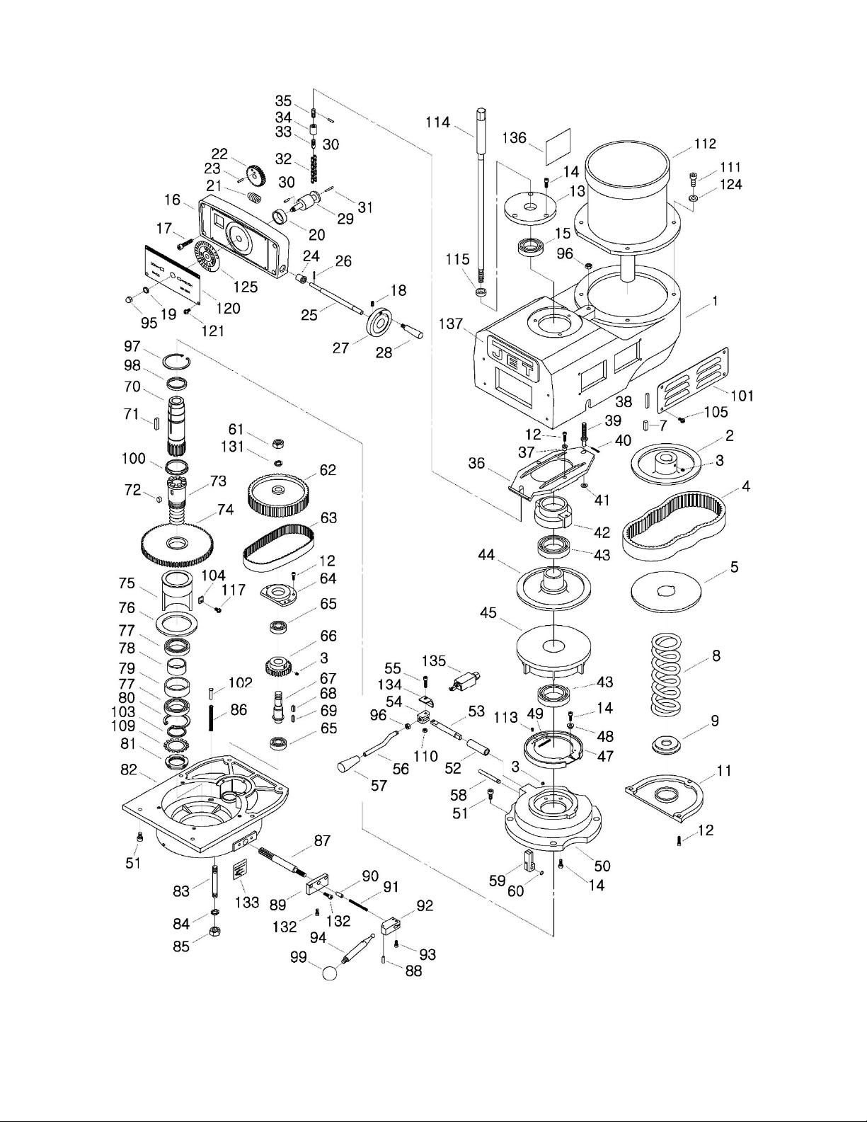
13.1.1 JTM-1050VS2 Upper Head Assembly – Exploded View
21

13.1.2 JTM-1050VS2 Upper Head Assembly – Parts List
Index No Part No Description Size Qty
1 ................ JTM949EVS-A77 ...... Upper Guard ............................................................ ...................................... 1
2 ................ JTM1254RVS-A02 .... Motor Disc – Upper .................................................. ...................................... 1
3 ................ TS-1523011 .............. Socket Set Screw .................................................... M6x6L ........................... 3
4 ................ JTM1254RVS-A04 .... Belt .......................................................................... 3828 -875L .................... 1
5 ................ JTM1254RVS-A05 .... Motor Disc – Lower .................................................. ...................................... 1
7 ................ 6295247 .................... Key .......................................................................... 7x7x25L mm ................. 1
8 ................ JTM1254RVS-A08 .... Spring ...................................................................... ...................................... 1
9 ................ JTM1254RVS-A09 .... Washer .................................................................... ...................................... 1
11 .............. JTM949EVS-A69 ...... Motor Pulley Cover .................................................. ...................................... 1
12 .............. TS-1504041 .............. Hex Socket Cap Screw ............................................ M8x20L ....................... 10
13 .............. JTM1254RVS-A13 .... Upper Cover ............................................................ ...................................... 1
14 .............. TS-1502041 .............. Hex Socket Cap Screw ............................................ M5x16L ....................... 10
15 .............. BB-6009ZZ ................ Ball Bearing ............................................................. 6009ZZ ......................... 1
16 .............. JTM1254RVS-A16 .... Dial Housing ............................................................ ...................................... 1
17 .............. TS-1503071 .............. Hex Socket Cap Screw ............................................ M6x30L ......................... 4
18 .............. TS-1523051 .............. Socket Set Screw .................................................... M6x16L ......................... 2
19 .............. JTM1254RVS-A19 .... Bushing .................................................................... ...................................... 1
20 .............. JTM1254RVS-A20 .... Spacer ..................................................................... ...................................... 1
21 .............. JTM1254RVS-A21 .... Worm Gear Shaft ..................................................... ...................................... 1
22 .............. JTM1254RVS-A22 .... Worm Gear ............................................................. ...................................... 1
23 .............. 5301041 .................... Spring Pin ................................................................ 5x10L mm ..................... 2
24 .............. JTM1254VS-A24 ....... Bushing .................................................................... ...................................... 2
25 .............. JTM1254VS-A25 ....... Shaft ........................................................................ ...................................... 1
26 .............. 5302611 .................... Spring Pin ................................................................ 3x12L mm ..................... 1
27 .............. JTM1254RVS-A27 .... Handwheel ............................................................... ...................................... 1
.................. JTM1254RVS-A27A .. Handwheel Assembly (includes #18,27,28) ............ ...................................... 1
28 .............. JTM1254RVS-A28 .... Handle ..................................................................... ...................................... 1
29 .............. JTM1254RVS-A29 .... Chain axle ................................................................ ...................................... 1
30 .............. 5509313 .................... Spring Pin ................................................................ 4x16L mm ..................... 2
31 .............. GA7X-865 ................. Spring Pin ................................................................ 3x25L mm ..................... 1
32 .............. JTM1254RVS-A32 .... Chain ....................................................................... ...................................... 1
33 .............. JTM1254RVS-A33 .... Screw ....................................................................... ...................................... 1
34 .............. JTM1254RVS-A34 .... Spacer ..................................................................... ...................................... 1
35 .............. JTM1254RVS-A35 .... Pin ........................................................................... ...................................... 1
36 .............. JTM1254RVS-A36 .... Adjustable Plate ....................................................... ...................................... 1
37 .............. JTM1254RVS-A37 .... Shift Sleeve ............................................................. ...................................... 2
38 .............. 6294761 .................... Key .......................................................................... 6x6x45L mm ................. 1
39 .............. JTM1254RVS-A39 .... Bottom Pin ............................................................... ...................................... 1
40 .............. 5307431 .................... Spring Pin ................................................................ 3/32"x3/4"...................... 1
41 .............. TS-1550061 .............. Flat Washer ............................................................. Ø8 mm .......................... 1
42 .............. JTM1254RVS-A42 .... Bearing Housing ...................................................... ...................................... 1
43 .............. BB-6010ZZ ................ Ball Bearing ............................................................. 6010ZZ ......................... 2
44 .............. JTM1254RVS-A44 .... Spindle Disc – Upper ............................................... ...................................... 1
45 .............. JTM1254RVS-A45 .... Spindle Disc – Lower ............................................... ...................................... 1
47 .............. JTM949EVS-A48 ...... Brake Shoe .............................................................. ...................................... 1
48 .............. JTM949EVS-A58 ...... Lock Collar ............................................................... ...................................... 1
49 .............. JTM949EVS-A62 ...... Brake Spring ............................................................ ...................................... 2
50 .............. JTM949EVS-A43 ...... Brake Base .............................................................. ...................................... 1
51 .............. TS-1504041 .............. Hex Socket Cap Screw ............................................ M8x20L ....................... 10
52 .............. JTM949EVS-A53 ...... Brake Sleeve ........................................................... ...................................... 1
53 .............. JTM949EVS-A54 ...... Spindle Brake Shaft ................................................. .................
54 .............. JTM949EVS-A56 ...... Spindle Brake Lever Pivot ....................................... ...................................... 1
55 .............. TS-1503071 .............. Hex Socket Cap Screw ............................................ M6x30L ......................... 1
56 .............. JTM949EVS-A63 ...... Spindle Brake Lever ................................................ ...................................... 1
57 .............. JTM949EVS-A50 ...... Brake Lock Knob ..................................................... 3/8" ................................ 1
58 .............. JTM949EVS-A49 ...... Brake Shaft .............................................................. ...................................... 1
59 .............. JTM949EVS-A47 ...... Brake Finger Stud (set of 2)..................................... ...................................... 1
60 .............. JTM949EVS-A46 ...... Retaining Ring ......................................................... STW8 ............................ 1
61 .............. TS-0581072 .............. Hex Nut .................................................................... 5/8-18UNF .................... 1
62 .............. JTM949EVS-A34 ...... Timing Pulley ........................................................... ...................................... 1
..................... 1
22

Index No Part No Description Size Qty
63 .............. JTM949EVS-A32 ...... Timing Belt ............................................................... 225L100 ........................ 1
64 .............. JTM949EVS-A19 ...... Ball Bearing Bracket ............................................... ...................................... 1
65 .............. BB-6203ZZ ................ Ball Bearing ............................................................. 6203ZZ ......................... 2
66 .............. JTM949EVS-A18 ...... Gear ......................................................................... ...................................... 1
67 .............. JTM949EVS-A16 ...... Gear Shaft ............................................................... ...................................... 1
68 .............. KF2R5515 ................. Double Round Key .................................................. 5x5x15L mm ................. 1
69 .............. KF2R5518 ................. Double Round Key .................................................. 5x5x18L mm ................. 1
70 .............. JTM949EVS-A41 ...... Input Clutch ............................................................. ...................................... 1
71 .............. 5307741 .................... Key .......................................................................... 8x7x24L mm ................. 1
72 .............. KF2R8712 ................. Key .......................................................................... 8x7x12L mm ................. 1
73 .............. JTM949EVS-A38 ...... Output Clutch ........................................................... ...................................... 1
74 .............. JTM949EVS-A33 ...... Gear ......................................................................... ...................................... 1
75 .............. JTM949EVS-A31 ...... Bearing Sleeve ........................................................ ...................................... 1
76 .............. JTM949EVS-A30 ...... Washer .................................................................... ...................................... 1
77 .............. BB-6908ZZ ................ Ball Bearing ............................................................. 6908ZZ ......................... 2
78 .............. JTM949EVS-A29 ...... Gear Bearing Spacer (Small) .................................. ...................................... 1
79 .............. JTM949EVS-A28 ...... Gear Bearing Spacer (Large) .................................. ...................................... 1
79A ............ JTM949EVS-A28A .... Gear Bearing Spacer Assembly (#78,79) ................ ...................................... 1
80 .............. RTW62 ...................... Retaining Ring ......................................................... RTW62 .......................... 1
81 .............. AN08 ......................... Bearing Nut .............................................................. AN08 ............................. 1
82 .............. JTM949EVS-A01 ...... Upper Pulley Housing .............................................. ...................................... 1
83 .............. JTM949EVS-A88 ...... Stud ......................................................................... 7/16"x4"......................... 3
84 .............. TS-0720101 .............. Spring Washer ......................................................... 7/16" .............................. 3
85 .............. TS-0561041 .............. Hex Nut .................................................................... 7/16"-14 ........................ 3
86 .............. JTM949EVS-A21 ...... Pressure Spring ...................................................... ...................................... 3
87 .............. JTM949EVS-A03 ...... Bull Gear Shifter Pinion Shaf t .................................. ...................................... 1
88 .............. B-56 ........................... Spring Pin ................................................................ 3x20L mm ..................... 1
89 .............. JTM949EVS-A04 ...... Hi-Lo Detent Plate ................................................... ...................................... 1
90 .............. JTM949EVS-A05 ...... Sleeve ...................................................................... ...................................... 1
91 .............. JTM949EVS-A06 ...... Spring ...................................................................... ...................................... 1
92 .............. JTM949EVS-A08 ...... Hi-Lo Pinion Block ................................................... ...................................... 1
93 .............. TS-1502031 .............. Hex Socket Cap Screw ............................................ M5x12L ......................... 2
94 .............. JTM949EVS-A09 ...... Hi-Lo Shift Handle ................................................... ...................................... 1
95 .............. F004478 .................... Cap Nut ................................................................... 5/16”-18UNC ................. 1
96 .............. TS-0570031 .............. Hex Nut .................................................................... 3/8”-16UNC ................... 2
97 .............. F006094 .................... C-Retaining Ring, Int ............................................... RTW80 .......................... 1
98 .............. JTM949EVS-A59 ...... Collar ....................................................................... ...................................... 1
99 .............. BH1/4 ....................... Black Plastic Ball ..................................................... 1/4" ................................ 1
100 ............ JTM949EVS-A39 ...... Clutch Collar ............................................................ ...................................... 1
101 ............ JTM949EVS-A75 ...... Side Belt Housing Cover ......................................... ...................................... 2
102 ............ JTM949EVS-A22 ...... Spring Shaft ............................................................. ...................................... 3
103 ............ JTM949EVS-A25 ...... Spacer ..................................................................... ...................................... 1
104 ............ JTM1254RVS-A104 .. Nut ........................................................................... ...................................... 1
105 ............ F009884 .................... Socket Head Button Screw ...................................... M5x8L ........................... 8
109 ............ AW08 ........................ Bearing Washer ....................................................... AW08 ............................ 1
110 ............ TS-1540041 .............. Hex Nut .................................................................... M6 ................................. 1
111 ............ TS-0209061 .............. Hex Socket Cap Screw ............................................ 3/8”-16x1-1/4L .............. 4
112 ............ JTM1050VS2-A112 .. Motor………………………………………………3HP 230/ 460V 4P 3Ph ........ 1
.................. JTM1050VS2-A112-1 Motor Fan (not shown)............................................. ...................................... 1
.................. JTM1050VS2-A112-2 Motor Fan Cover (not shown) .................................. ...................................... 1
.................. JTM1050VS2-A112-3 Junction Box Cover (not shown) .............................. ..........................
113 ............ JTM949EVS-A51 ...... Pan Head Screw ...................................................... 1/8"x1/4"........................ 4
114 ............ JTM949EVS-A87 ...... Draw Bar .................................................................. 7/16" .............................. 1
115 ............ JTM949EVS-A86 ...... Spacer ..................................................................... ...................................... 1
117 ............ F000233 .................... Phillips Pan Hd Machine Screw ............................... #10-24x1/2"L ................. 1
120 ............ JTM1050VS2-A120 ... Speed Plate ............................................................. 60-4200 RPM ................ 1
121 ............ TS-2244202 .............. Socket Head Button Screw ...................................... M4x20L ......................... 4
124 ............ TS-1550071 .............. Flat Washer ............................................................. M10 ............................... 4
125 ............ JTM1050VS2-A125 ... Speed Dial ............................................................... 60-4200 RPM ................ 1
131 ............ TS-0720131 .............. Spring Washer ......................................................... 5/8" ................................ 1
132 ............ TS-1502041 .............. Hex Socket Cap Screw ............................................ M5x16L ......................... 3
133 ............ JTM1050VS2-A133 ... Speed Range Label ................................................. 60-4200 RPM ................ 1
............ 1
23

Index No Part No Description Size Qty
134 ............ JTM949EVS-A91 ...... Push Plate ............................................................... ...................................... 1
135 ............ JTM949EVS-A92 ...... Limit Switch ............................................................. ...................................... 1
136 ............ JTM1050VS2-A136 ... Motor Label .............................................................. ...................................... 1
137 ............ JET-165 ..................... JET Logo ................................................................. 165 x 68 mm ................. 1
24

13.2.1 JTM-1050VS2 Lower Head Assembly – Exploded View
25

13.2.2 JTM-1050VS2 Lower Head Assembly – Parts List
Index No Part No Description Size Qty
1 ................ TS-1503031 .............. Hex Socket Cap Screw ............................................ M6x12L ......................... 1
2 ................ TS-1550041 .............. Flat Washer ............................................................. Ø6xØ16x2t .................... 1
3 ................ JTM949EVS-B07 ...... Worm Gear Spacer .................................................. ...................................... 1
3A .............. JTM949EVS-B03A .... Feed Gear Assembly (includes #1-7,12-17,36-37and 40-41) ........................ 1
4 ................ JTM949EVS-B08 ...... Feed Drive Worm Gear ........................................... ...................................... 1
5 ................ JTM949EVS-B05 ...... Worm Cradle Bushing.............................................. ...................................... 1
6 ................ KF2R3312 ................. Key .......................................................................... 3x3x12L ........................ 1
7 ................ JTM949EVS-B06 ...... Feed Gear Shaft ...................................................... ...................................... 1
8 ................ TS-1502031 .............. Hex Socket Cap Screw ............................................ M5x12 ........................... 6
12 .............. TS-1503041 .............. Hex Socket Cap Screw ............................................ M6x16L ......................... 1
13 .............. JTM949EVS-B13 ...... Flat Washer ............................................................. Ø6 ................................. 1
14 .............. KF2R5508 ................. Key .......................................................................... 5x5x8L .......................... 1
15 .............. JTM949EVS-B15 ...... Feed Reverse Bevel Gear ....................................... ...................................... 1
16 .............. JTM949EVS-B16 ...... Feed Engage Pin ..................................................... ...................................... 1
17 .............. JTM949EVS-B17 ...... Worm Gear Cradle................................................... ...................................... 1
18 .............. JTM949EVS-B18 ...... Cam Rod ................................................................. ...................................... 1
19 .............. JTM949EVS-B19 ...... Shift Sleeve ............................................................. ...................................... 1
20 .............. JTM949EVS-B20 ...... Lock Rod ................................................................. ...................................... 2
21 .............. JTM949EVS-B21 ...... Spring ...................................................................... ...................................... 3
22 .............. 5302731 .................... Socket Set Screw .................................................... M8x6L ........................... 2
23 .............. JTM949EVS-B23 ...... Crank ....................................................................... ...................................... 2
24 .............. BH1/4 ........................ Black Plastic Ball ..................................................... 1/4" ................................ 3
25 .............. JTM949EVS-B25 ...... Indicator Rod .......................................................... ...................................... 1
26 .............. JTM949EVS-B26 ...... Indicator Rod Screw ............................................... ...................................... 1
27 .............. JTM949EVS-B27 ...... Upper Bushing ......................................................... ...................................... 1
28 .............. JTM949EVS-B28 ...... Cluster Gear ............................................................ ...................................... 1
29 .............. KF2R3345 ................. Key .......................................................................... 3x3x45L mm ................. 1
31 .............. JTM949EVS-B31 ...... Bevel Gear Shaft ..................................................... ...................................... 1
32 .............. STW16 ...................... Retaining Ring ......................................................... STW16 .......................... 2
33 .............. JTM949EVS-B33 ...... Bevel Gear Bushing ................................................. ...................................... 1
34 .............. JTM949EVS-B34 ...... Spacer ..................................................................... ...................................... 1
36 .............. JTM949EVS-B36 ...... Feed Drive Gear ...................................................... ...................................... 1
36A ............ JTM949EVS-B36A .... Feed Drive Gear Assembly (#36,37) ....................... ...................................... 1
37 .............. KF2R3308 ................. Key .......................................................................... 3x3x8L mm ................... 1
40 .............. JTM949EVS-B40 ...... Feed Drive Gear ...................................................... ...................................... 1
41 .............. BB-BA78Z ................. Needle Bearing ........................................................ BA78Z ........................... 1
42 .............. JTM949EVS-B42 ...... Bushing .................................................................... ...................................... 1
43 .............. JTM949EVS-B43 ...... Worm ....................................................................... ...................................... 1
44 .............. JTM949EVS-B44 ...... Feed Worm Shaft Bushing ...................................... ...................................... 1
47 .............. JTM949EVS-B47 ...... Bevel Gear Thrust Spacer ....................................... ...................................... 1
48 .............. JTM949EVS-B48 ...... Bushing .................................................................... ...................................... 2
49 .............. JTM949EVS-B49 ...... Feed Reverse Bevel Gear ....................................... ...................................... 2
50 .............. JTM949EVS-B50 ...... Feed Reverse Clutch ............................................... ...................................... 1
55 .............. JTM949EVS-B55 ...... Reverse Clutch Rod................................................. ...................................... 1
56 .............. TS-209203 ................ Spring Pin ................................................................ Ø3x20L mm .................. 1
57 .............. JTM949EVS-B57 ...... Feed Worm Shaft .................................................... ...................................... 1
59 .............. 5302611 .................... Spring Pin ................................................................ 3x12 mm ....................... 2
60 .............. JTM949EVS-B60 ...... Feed Shift Rod ......................................................... ...................................... 1
61 .............. TS-1522031 .............. Socket Set Screw .................................................... M5x10 ........................... 1
62 .............. KF2R3315 ................. Key .......................................................................... 3x3x15 mm ................... 1
63 .............. JTM949EVS-B63 ...... Feed Gear Shift Fork ............................................... ..................
64 .............. JTM949EVS-B64 ...... Cluster Gear Shift Crank.......................................... ...................................... 1
66 .............. JTM949EVS-B66 ...... Cluster Gear Cover .................................................. ...................................... 1
67 .............. TS-1502031 .............. Hex Socket Cap Screw ............................................ M5x12L ......................... 4
69 .............. JTM949EVS-B69 ...... Lock Block ............................................................... ...................................... 1
70 .............. 2210-266 ................... Retaining Ring ......................................................... STW30 .......................... 1
71 .............. JTM949EVS-B71 ...... Spring ...................................................................... 10x20L mm ................... 1
72 .............. JTM949EVS-B72 ...... Quill Housing ........................................................... 85mm ........................... 1
73 .............. TS-1502081 .............. Hex Socket Cap Screw ............................................ M5x35L ......................... 2
74 .............. JTM949EVS-B74 ...... Clutch Ring Pin ........................................................ ...................................... 2
.................... 1
26

Index No Part No Description Size Qty
75 .............. JTM949EVS-B75 ...... Clutch Ring .............................................................. ...................................... 1
76 .............. 5302731 .................... Socket Set Screw .................................................... M8x6L ........................... 2
77 .............. JTM949EVS-B77 ...... Handle ..................................................................... ...................................... 1
78 .............. JTM949EVS-B78 ...... Overload Clutch Lockout ......................................... ...................................... 1
79 .............. JTM949EVS-B79 ...... Safety Clutch Spring ................................................ ...................................... 1
80 .............. JTM949EVS-B80 ...... Overload Clutch ....................................................... ...................................... 1
80A ............ JTM949EVS-B80A .... Overload Clutch Assembly (#78,80,81) ................... ...................................... 1
81 .............. JTM949EVS-B81 ...... Overload Clutch Sleeve ........................................... ...................................... 1
82 .............. KF2R5516 ................. Key .......................................................................... 5x5x16L ........................ 1
83 .............. TS-1532052 .............. Pan Head Machine Screw ....................................... M4x16L ......................... 3
84 .............. JTM949EVS-B84 ...... Handle .................................................................... ...................................... 1
85 .............. TS-1523031 .............. Socket Set Screw .................................................... M6x10L ......................... 2
86 .............. JTM949EVS-B86 ...... Worm Shaft .............................................................. ...................................... 1
87 .............. TS-1523011 .............. Set Screw ................................................................ M6X6L .......................... 1
88 .............. JTM949EVS-B88 ...... Spring ...................................................................... ...................................... 1
89 .............. JTM949EVS-B89 ...... Spring Plunger ......................................................... ...................................... 1
90 .............. JTM949EVS-B90 ...... Pinion Shaft ............................................................. ...................................... 1
91 .............. JTM949EVS-B91 ...... Spacer ..................................................................... ...................................... 1
92 .............. JTM949EVS-B92 ...... Overload Clutch Worm Gear ................................... ...................................... 1
93 .............. JTM949EVS-B93 ...... Overload Clutch Ring .............................................. ...................................... 1
94 .............. STW22 ...................... Retaining Ring ......................................................... STW22 .......................... 1
95 .............. JTM949EVS-B95 ...... Worm Gear .............................................................. ...................................... 1
96 .............. JTM949EVS-B96 ...... Trip Lever ................................................................ ...................................... 1
96-1 ........... GA7X-122 ................. Spring Pin ................................................................ Ø5x20L mm .................. 1
97 .............. JTM949EVS-B97 ...... Washer .................................................................... ...................................... 1
98 .............. STW10 ...................... Retaining Ring ......................................................... STW10 .......................... 1
99 .............. JTM949EVS-B99 ...... Clutch Arm Cover .................................................... ...................................... 1
100 ............ TS-1523051 .............. Socket Set Screw .................................................... M6x16L ......................... 1
101 ............ TS-2311061 .............. Hex Nut .................................................................... M6 ................................. 1
102 ............ 5625391 .................... Spring Pin ................................................................ Ø5x16L mm .................. 1
103 ............ JTM949EVS-B103 .... Cam Rod ................................................................. ...................................... 1
104 ............ JTM949EVS-B104 .... Trip Handle .............................................................. ...................................... 1
105 ............ 5302731 .................... Socket Set Screw .................................................... M8x6L ........................... 1
106 ............ JTM949EVS-B106 .... Feed Trip Bracket .................................................... ...................................... 1
107 ............ TS-1503051 .............. Hex Socket Cap Screw ............................................ M6x20L ......................... 2
108 ............ JTM949EVS-B108 .... Plunger .................................................................... ...................................... 1
109 ............ KF2R3312 ................. Key .......................................................................... 3x3x12L ........................ 1
110 ............ JTM949EVS-B110 .... Feed Reverse Stud Bolt........................................... ...................................... 1
110A .......... JTM949EVS-B110A .. Feed Reverse Stud Assembly (#110,111,112) ........ ...................................... 1
111 ............ JTM949EVS-B111 .... Feed Reverse Stud .................................................. ...................................... 1
112 ............ ETW6 ........................ Retaining Ring ......................................................... ETW6 ............................ 1
113 ............ JTM949EVS-B113 .... Handwheel Clutch ................................................... ...................................... 1
114 ............ SB-3/16 ..................... Steel Ball ................................................................. 3/16" .............................. 2
115 ............ JTM949EVS-B115 .... Spring ...................................................................... ...................................... 2
116 ............ JTM949EVS-B116 .... Lever ........................................................................ ...................................... 1
117 ............ JTM949EVS-B117 .... Spring Pin ................................................................ Ø3X16L mm .................. 1
118 ............ JTM949EVS-B118 .... Cam Rod Sleeve Assembly ..................................... ...................................... 1
119 ............ TS-1523011 .............. Socket Set Screw .................................................... M6x6L ........................... 2
120 ............ JTM949EVS-B120 .... Flat Washer ............................................................. M13 ............................... 4
121 ............ JTM949EVS-B121 .... Trip Plunger ............................................................. ...................................... 1
122 ............ JTM949EVS-B122 .... Adjustable Spring .................................................... ...................................... 1
123 ............ JTM949EVS-B123 .... Bushing .................................................................... ...................................... 1
124 ............ JTM949EVS-B124 .... Feed Trip Plunger .................................................... ...................................... 1
125 ............ JTM949EVS-B125 .... Handwheel ............................................................... ...................................... 1
125A .......... JTM949EVS-B125A .. Handwheel Assembly (#125,126) ............................ ...................................... 1
126 ............ JTM949EVS-B126 .... Handle ..................................................................... ...................................... 1
127 ............ JTM949EVS-B127 .... Spindle ..................................................................... R8 ................................. 1
128 ............ JTM949EVS-B128 .... Quill Skirt ................................................................. ...................................... 1
129 ............ JTM949EVS-B129 .... Lock Nut .................................................................. M35 ............................... 1
130 ............ JTM949EVS-B130 .... Spring Cover ............................................................ ...................................... 1
131 ............ BB-6206ZZ ................ Ball Bearing ............................................................. 6206ZZ ......................... 1
132 ............ JTM949EVS-B132 .... Hub Sleeve .............................................................. ...................................... 1
27

Index No Part No Description Size Qty
133 ............ JTM949EVS-B133 .... Nose Piece .............................................................. ...................................... 1
134 ............ JTM949EVS-B134 .... Spindle Shield .......................................................... ...................................... 1
135 ............ BB-7207C .................. Ball Bearing ............................................................. 7207C ........................... 2
136 ............ JTM949EVS-B136 .... Bearing Spacer (large) ............................................ ...................................... 1
136A .......... JTM949EVS-B136A .. Bearing Spacer Assembly (#136,137) ..................... ...................................... 1
137 ............ JTM949EVS-B137 .... Bearing Spacer (small) ............................................ ...................................... 1
138 ............ JTM949EVS-B138 .... Hub .......................................................................... ...................................... 1
139 ............ TS-0270011 .............. Socket Set Screw .................................................... 5/16"-18x1/4" ................ 1
140 ............ TS-1523011 .............. Socket Set Screw .................................................... M6x6 ............................. 1
141 ............ JTM949EVS-B141 .... Pinion Shaft Hub ...................................................... ...................................... 1
142 ............ JTM949EVS-B142 .... Quill ......................................................................... ...................................... 1
143 ............ TS-1540021 .............. Hex Nut .................................................................... M4 ................................. 1
144 ............ TS-1521071 .............. Socket Set Screw .................................................... M4x20L ......................... 1
145 ............ JTM949EVS-B145 .... Feed Trip Lever ....................................................... ...................................... 1
146 ............ JTM949EVS-B146 .... Trip Lever Pin .......................................................... ...................................... 1
147 ............ KF2R5525 ................. Key .......................................................................... 5x5x25L ........................ 1
148 ............ JTM949EVS-B148 .... Quill Lock Sleeve ..................................................... ...................................... 1
148-1 ......... JTM949EVS-B148-1 . Spring ...................................................................... ...................................... 1
149 ............ JTM949EVS-B149 .... Lock Handle ............................................................. M8x80L ......................... 1
150 ............ TS-1533032 .............. Pan Head Screw ...................................................... M5x10L ......................... 2
151 ............ JTM949EVS-B151 .... Washer .................................................................... ...................................... 1
152 ............ JTM949EVS-B152 .... T-type Pin ................................................................ ...................................... 1
153 ............ JTM949EVS-B153 .... Quill Lock Sleeve ..................................................... ...................................... 1
154 ............ JTM949EVS-B154 .... Quill Pinion Shaft ..................................................... ...................................... 1
154A .......... JTM949EVS-B154A .. Quill Pinion Shaft Assembly (#152,154) .................. ...................................... 1
155 ............ JTM949EVS-B155 .... T-Bolt Assembly....................................................... ...................................... 4
156 ............ JTM949EVS-B156 .... Spacer ..................................................................... ...................................... 4
157 ............ JTM949EVS-B157 .... Lock Nut .................................................................. ...................................... 4
158 ............ TS-2171012 .............. Pan Head Screw ...................................................... M4x6L ........................... 2
159 ............ JTM949EVS-B159 .... Micrometer Scale ..................................................... ...................................... 1
160 ............ TS-0209032 .............. Hex Socket Cap Screw ............................................ 3/8"-24UNFx3/4" ........... 1
162 ............ JTM949EVS-B162 .... Micrometer Nut ........................................................ ...................................... 1
163 ............ JTM949EVS-B163 .... Quill Stop Knob ........................................................ ...................................... 1
164 ............ JTM949EVS-B164 .... Quill Micro-Screw..................................................... ...................................... 1
165 ............ TS-1502051 .............. Hex Socket Cap Screw ............................................ M5x20L ......................... 1
166 ............ TS-1540031 .............. Hex Nut .................................................................... M5 ................................. 1
171 ............ KF2R4418 ................. Key .......................................................................... 4x4x18L mm ................. 1
172 ............ JTM1050VS2-B172 ... Bracket .................................................................... ...................................... 1
173 ............ JTM1050VS2-B173 ... Reversible Switch .................................................... ...................................... 1
174 ............ JTM1050VS2-B174 ... Switch Housing ........................................................ ...................................... 1
175 ............ JTM1050VS2-B175 ... Cable Gland ............................................................. PG-13.5 ........................ 2
28

13.3.1 JTM-1050VS2 Column and Base Assembly – Exploded View
29

13.3.2 JTM-1050VS2 Column and Base Assembly – Parts List
Index No Part No Description Size Qty
1 ................. TS-2249252 ................ Socket Head Button Screw .......................................... M10x25L ......................... 4
2 ................. JTM949EVS-C31 ........ Bushing ........................................................................ ........................................ 2
3 ................. JTM949EVS-C30 ........ Nut ............................................................................... ........................................ 2
4 ................. JTM1050EVS2-C04 .... Table ............................................................................ 10"x50" ............................ 1
5 ................. JTM1050EVS2-C05 .... Flat Way Cover ............................................................ ........................................ 1
6 ................. TS-2245102 ................ Socket Head Button Screw .......................................... M5x10L ......................... 24
6-1 .............. TS-2245162 ................ Socket Head Button Screw .......................................... M5x16L ........................... 4
7 ................. JTM1050EVS2-C07 .... T Rubber ...................................................................... 16x32mm ........................ 6
8 ................. JTM949EVS-C34 ........ Adjust Screw ................................................................ M8x37L ........................... 6
9 ................. JTM1050EVS2-C09 .... Table Gib ..................................................................... ........................................ 1
10 ............... JTM1050EVS2-C10 .... Saddle .......................................................................... ........................................ 1
11 ............... JTM1050EVS2-11 ....... Handle ......................................................................... M12x50L ......................... 1
12 ............... JTM1050EVS2-C12 .... Lock Pin ....................................................................... ........................................ 1
13 ............... JTM1050EVS2-C13 .... Limiter .......................................................................... ........................................ 1
14 ............... TS-1504041 ................ Hex Socket Cap Screw ................................................ M8x20L ........................... 2
15 ............... JTM1050EVS2-C15 .... Locker .......................................................................... ........................................ 2
16 ............... JTM1050EVS2-16 ....... Spring .......................................................................... ........................................ 2
17 ............... JTM1050EVS2-17 ....... Handle ......................................................................... M12x103L ....................... 2
18 ............... JTM1050EVS2-18 ....... Pin ................................................................................ ........................................ 2
19 ............... JTM1050EVS2-19 ....... Saddle Knee Gib .......................................................... ........................................ 1
20 ............... JTM1050EVS2-20 ....... Lock Screw .................................................................. ........................................ 2
21 ............... TS-1524031 ................ Socket Set Screw ......................................................... M8x12L ........................... 2
22 ............... JTM1050EVS2-22 ....... Front Wiper .................................................................. ........................................ 1
22-1 ............ JTM1050EVS2-22-1 .... Rear Wiper ................................................................... ........................................ 1
23 ............... JTM1050EVS2-23 ....... Pleated Way Cover ...................................................... ........................................ 1
24 ............... JTM1050EVS2-24 ....... Shaft ............................................................................ ........................................ 1
25 ............... JTM1050EVS2-25 ....... Washer ........................................................................ ........................................ 2
26 .............. JTM949EVS-C07 ...... Worm ....................................................................... Ø44.4x17.4x50.7L ........ 1
27 .............. TS-1523021 .............. Socket Set Screw .................................................... M6x8L ........................... 1
28 .............. KEY5550 ................... Key .......................................................................... 5x5x50L mm ................. 1
29 .............. JTM1050EVS2-C29A Lifting Ring ............................................................... M20 ............................... 1
30 .............. JTM1050EVS2-30 ..... Ram ......................................................................... ...................................... 1
30-1 ........... JTM1050EVS2-30-1 .. Plate ........................................................................ ...................................... 1
31 .............. JTM1050EVS2-30-1 .. Plate ........................................................................ ...................................... 1
32 .............. JTM1050EVS2-32 ..... Adapter Locking Bolt ............................................... M14x203L ..................... 3
33 .............. 6293347 .................... Spring Pin ................................................................ Ø3x16L mm .................. 1
34 .............. JTM1050EVS2-34 ..... Adapter Shaft ........................................................... Ø30x200L mm .............. 1
35 .............. RN2L6 ....................... Rivet ........................................................................ Ø2x6L mm .................. 12
36 .............. JTM949EVS-C12 ...... Angle Scale ............................................................. ...................................... 1
37 .............. JTM949EVS-C06 ...... Adapter Scale .......................................................... ...................................... 1
38 .............. TS-1521031 .............. Set Screw ................................................................ M4x8L ........................... 1
39 .............. JTM1050EVS2-39 ..... Lock Nut .................................................................. Ø45x13L ....................... 1
40 .............. JTM1050EVS2-C40 .. Ram Adapter ........................................................... Ø30 mm ........................ 1
40-1 ........... JTM949EVS-C03-1 ... Lock Stud ................................................................. ...................................... 1
41 .............. JTM949EVS-C02 ...... Worm Gear .............................................................. ...................................... 1
42 .............. AB1012W-A83 .......... Spring Pin ................................................................ Ø6x30L mm .................. 1
43 .............. TS-1504061 .............. Hex Socket Cap Screw ............................................ M8x30L ......................... 2
45 .............. JTM1050EVS2-45 ..... Knee Wiper (Left) .................................................... ...................................... 1
46 .............. JTM1050EVS2-46 ..... Knee Wiper (Right) .................................................. ...................................... 1
47 .............. JTM1050EVS2-47 ..... Gib ........................................................................... ...................................... 1
48 .............. JTM949EVS-C21 ...... Lock Handle Assembly ............................................ M12x25L ....................... 5
49 .............. JTM1050EVS2-49 ..... Lock Pin .................................................................. Ø10*37L*50° mm .......... 2
50 .............. JTM1050EVS2-50 ..... Knee ........................................................................ ...................................... 1
51 .............. JTM949EVS-C48 ...... Chip Guard (Bottom) ............................................... 580MM L ....................... 1
52 .............. JTM949EVS-C49 ...... Chip Guard (Middle) ................................................ 470MM L ....................... 1
53 .............. JTM949EVS-C41 ...... Chip Guard (Top) ..................................................... 360MM L ....................... 1
62 .............. TS-1523021 .............. Socket Set Screw .................................................... M6x8L ........................... 2
63 .............. JTM949EVS-C74 ...... Bevel Gear ............................................................... 18T ................................ 1
64 .............. BB-6004ZZ ................ Bearing .................................................................... 6004ZZ ......................... 1
65 .............. KF2R4418 ................. Key .......................................................................... 4x4x18L mm ................. 1
66 .............. JTM1050EVS2-66 ..... Elevating Shaf t ........................................................ ...................................... 1
67 .............. KF2R4418 ................. Key .......................................................................... 4x4x18L mm ................. 1
30

Index No Part No Description Size Qty
68 .............. BB-6204ZZ ................ Bearing .................................................................... 6204ZZ ......................... 1
69 .............. JTM949EVS-C68 ...... Housing ................................................................... DISTANCE 62 ............... 1
70 .............. TS-1503041 .............. Hex Socket Cap Screw ............................................ M6x16L ......................... 3
71 .............. JTM949EVS-C67 ...... Dial Holder ............................................................... 51L ................................ 1
72 .............. JTM949EVS-C66 ...... Dial (Inch) ................................................................ 100/0.001" ..................... 1
73 .............. JTM949EVS-C65 ...... Dial Lock Nut ........................................................... ...................................... 1
74 .............. JTM949EVS-C64 ...... Clutch Insert ............................................................ 4mm, 9T ........................ 1
75 .............. JTM1050EVS2-75 ..... Elevating Crank ....................................................... ...................................... 1
76 .............. JTM949EVS-C62 ...... Handle ..................................................................... ...................................... 1
79 .............. JTM1050EVS2-79 ..... Turret Gib ................................................................ ...................................... 1
80 .............. JTM1050EVS2-80 ..... Turret ....................................................................... ...................................... 1
81 .............. SNH12L150 ............... Hex Cap Screw ........................................................ M12x150L ..................... 4
82 .............. TS-2361121 .............. Spring Washer ......................................................... Ø13 mm ........................ 4
83 .............. TS-2279301 .............. Socket Set Screw .................................................... M10x30L ....................... 1
83-1 ........... TS-1540071 .............. Hex Nut ................................................................... M10 ............................... 1
84 .............. JTM1050EVS2-84 ..... Locking Bolt ............................................................. M14x110 ....................... 2
85 .............. JTM1050EVS2-85 ..... Table Lock Piece ..................................................... ...................................... 2
86 .............. TS-155009 ................ Flat Washer ............................................................. Ø14 mm ........................ 2
87 .............. TS-154009 ................ Hex Nut ................................................................... M14 ............................... 2
88 .............. JTM1050EVS2-88 ..... Ram Pinion .............................................................. M2.54-13T .................... 1
91 .............. JTM1050EVS2-91 ..... Locking Screw ......................................................... M8x30L ......................... 2
92 .............. TS-1524011 .............. Socket Set Screw .................................................... M8x8L ........................... 2
93 .............. JTM949EVS-C81 ...... Turret Scale ............................................................. ...................................... 1
94 .............. JTM949EVS-C27 ...... Spider ...................................................................... ...................................... 1
95 .............. JTM949EVS-C28 ...... Column .................................................................... ...................................... 1
96 .............. TS-2246122 .............. Socket Head Button Screw ...................................... M6x12L ......................... 6
97 .............. JTM949EVS-C86 ...... Cover ....................................................................... ...................................... 1
98 .............. JTM949EVS-C87 ...... Strainer Net ............................................................. ...................................... 2
99 .............. TS-1503041 .............. Hex Socket Cap Screw ............................................ M6x16L ......................... 3
100 ............ JTM949EVS-C53 ...... Lead Screw Nut ....................................................... Ø32 x 5 TPI ................... 1
101 ............ JTM949EVS-C52 ...... Brass Nut ................................................................. ...................................... 1
102 ............ TS-1505051 .............. Hex Socket Cap Screw ............................................ M10x35L ....................... 2
103 ............ TS-2361101 .............. Lock Washer ............................................................ M10 ............................... 2
104 ............ TS-1540071 .............. Hex Nut .................................................................... M10 ............................... 1
105 ............ SH(PT)1/2B ............... Oil Plug .................................................................... 1/2"PT ........................... 3
109 ............ TS-0561052 .............. Hex Nut ................................................................... 1/2"-20UNF ................... 1
110 ............ TS-155009 ................ Washer .................................................................... Ø13xØ32x5t mm ........... 1
111 ............ JTM949EVS-C58 ...... Bevel Gear ............................................................... 36T ................................ 1
113 ............ BB-6205ZZ ................ Bearing .................................................................... 6205ZZ ......................... 1
114 ............ BB-51305 .................. Thrust Bearing ......................................................... 51305 ............................ 1
116 ............ TS-0720111 .............. Spring Washer ......................................................... Ø13 mm ........................ 1
117 ............ KF2R5520 ................. Key .......................................................................... 5x5x20L mm ................. 1
118 ............ JTM949EVS-C61 ...... Lead Screw (Inch) ................................................... Ø32x5TPI (570L) .......... 1
121 ............ JTM1254VS-C91 ....... Pointer ..................................................................... ...................................... 2
122 ............ JTM949EVS-C84 ...... Side Cover ............................................................... ...................................... 1
123 ............ JET-254 ..................... JET Logo ................................................................. 254x105 mm ................. 2
124 ............ LM000357 ................. ID/Warning Label ..................................................... ...................................... 1
.................. JTM1050VS2-TB ....... Tool Box Kit Complete (not shown) ......................... ...................................... 1
31

13.4.1 JTM-1050VS2 Table Leadscrew Assembly – Exploded View
13.4.2 JTM-1050VS2 Table Leadscrew Assembly – Parts List
Index No Part No Description Size Qty
1 ................ TS-0561052 .............. Hex Nut .................................................................... 1/2"-20UNF ................... 3
2 ................ JTM949EVS-D02 ...... Handle ..................................................................... 3/8" ................................ 3
3 ................ JTM949EVS-D03 ...... Ball Crank ................................................................ ...................................... 3
4 ................ JTM949EVS-D04 ...... Dial Nut .................................................................... ...................................... 3
5 ................ JTM949EVS-D05 ...... Dial (Inch) ................................................................ 200/0.001" ..................... 3
6 ................ JTM949EVS-D06 ...... Dial Holder ............................................................... ...................................... 3
7 ................ TS-1503031 .............. Hex Socket Cap Screw ............................................ M6x12 ........................... 9
8 ................ JTM1050VS2-D08 ..... Cover ....................................................................... ...................................... 3
9 ................ BB-6204ZZ ................ Ball Bearing ............................................................. 6204ZZ ......................... 5
10 .............. JTM1050VS2-D10 ..... Bearing Bracket ....................................................... PCD Ø60 ...................... 2
11 .............. 5311251 .................... Spring Pin ................................................................ Ø5x30 mm .................... 6
12 .............. TS-1505031 .............. Hex Socket Cap Screw ............................................ M10x25 ....................... 16
13 .............. KF2R3325 ................. Key .......................................................................... 3x3x25 mm ................... 3
14 .............. JTM1050EVS2-D14 .. Longitudinal Feed Screw ......................................... Ø32 x 5tpi (1531L) ........ 1
15 .............. TS-1503041 .............. Hex Socket Cap Screw ............................................ M6x16 ......................... 10
16 .............. TS-1550041 .............. Flat Washer ............................................................. M6 ................................. 4
17 .............. JTM949EVS-D17 ...... Longitudinal Feed Adjustment Nut (inch) ................ Ø32 x 5 TPI ................... 1
17-1 ........... JTM949EVS-D17-1 ... Feed Screw Nut (inch) ............................................ Ø32 x 5 TPI ................... 1
18 .............. JTM1050EVS2-D18 .. Feed Nut Bracket ..................................................... ...................................... 1
20 .............. JTM1050VS2-D20 ..... Cross Feed Bearing Bracket ................................... PCD Ø60 ...................... 1
21 .............. JTM1050EVS2-D21 .. Cross Feed Screw ................................................... Ø32 x 5 TPI (720L) ....... 1
22 .............. JTM949EVS-D22 ...... Cross Feed Adjustment Nut (inch) .......................... Ø32 x 5 tpi .................... 1
22-1 ........... JTM949EVS-D22-1 ... Cross Feed Nut (inch) ............................................. Ø32 x 5 tpi .................... 1
23 .............. JTM949EVS-D23 ...... Adjusting Washer .................................................... Ø45xØ34x0.075t mm .... 2
32

13.5.1 JTM-1050VS2 Spindle Guard Assembly – Exploded View
13.5.2 JTM-1050VS2 Spindle Guard Assembly – Parts List
Index No Part No Description Size Qty
.................. JTM949EVS-SGA ..... Spindle Guard Assembly (#1 thru 10) ..................... ...................................... 1
1 ................ TS-1502101 .............. Hex Socket Cap Screw ............................................ M5x45L ........................ 2
2 ................ JTM949EVS-H02 ...... Support Plate ........................................................... ...................................... 1
3 ................ TS-2245102 .............. Socket Head Button Screw ...................................... M5x10L ......................... 2
4 ................ JTM949EVS-H04 ...... Bushing Bracket ...................................................... ...................................... 1
.................. JTM949EVS-H04A .... Bushing Bracket Assembly (includes #4,5,10) ........ ...................................... 1
5 ................ JTM949EVS-H05 ...... Bushing .................................................................... ...................................... 1
6 ................ JTM949EVS-H06 ...... Support Rod ............................................................ ...................................... 1
7 ................ TS-1550031 .............. Flat Washer ............................................................. Ø5 mm .......................... 2
8 ................ TS-1502031 .............. Hex Socket Cap Screw ............................................ M5x12L ......................... 2
9 ................ JTM949EVS-H09 ...... Spindle Guard .......................................................... ...................................... 1
10 .............. TS-1522021 .............. Socket Set Screw .................................................... M5x8L ........................... 1
33

13.6.1 JTM-1050VS2 One-Shot Lubrication System – Exploded View
13.6.2 JTM-1050VS2 One-Shot Lubrication System – Parts List
Index No Part No Description Size Qty
1 ................ LT-8 ........................... Manual Oiler ............................................................ ...................................... 1
2 ................ TS-1503061 .............. Hex Socket Cap Screw ............................................ M6x25L ......................... 4
3 ................ JTM949EVS-J09 ....... Distributor ................................................................ Ø4mm, 8 holes ............. 1
4 ................ TS-1502061 .............. Hex Socket Cap Screw ............................................ M5x25L ......................... 3
5 ................ JTM1050VS2-05 ....... Flexible Steel Tube .................................................. Ø4-500MM .................... 1
6 ................ PH-1-1/PB-4 .............. Check Joint .............................................................. 1/8PT ............................ 2
7 ................ JTM949EVS-J04 ....... Elbow Adapter ......................................................... 1/8PT ............................ 4
8 ................ PKD-4 ........................ T-Joint ...................................................................... Ø4mm, 3 holes ............. 1
9 ................ JTM1050VS2-09 ....... Grease Nipple .......................................................... 1/8PT ............................ 1
10 .............. AP-180 ...................... Aluminum Pipe ........................................................ Ø4x180L mm ................ 1
11 .............. AP-290 ...................... Aluminum Pipe ........................................................ Ø4x290L mm ................ 2
12 .............. AP-380 ...................... Aluminum Pipe ........................................................ Ø4x380L mm ................ 2
13 .............. AP-480 ...................... Aluminum Pipe ........................................................ Ø4x480L mm ................ 1
34

13.6.1 JTM-1050VS2 Work Lamp & Connector Box – Exploded View
13.6.2 JTM-1050VS2 Work Lamp & Connector Box – Parts List
Index No Part No Description Size Qty
1 ................ JTM1050VS2-G01 .... Pan Head Screw ...................................................... M4x16L ......................... 4
2 ................ JTM1050VS2-G02 .... Plastic Connector Box Cover ................................... ...................................... 1
3 ................ JTM1050VS2-G03 .... Terminal Block ......................................................... ...................................... 1
4 ................ JTM1050VS2-G04 .... Cable Gland ............................................................. M20S ............................ 1
5 ................ JTM1050VS2-G05 .... Plastic Connector Box ............................................. ...................................... 1
6 ................ JTM1050VS2-G06 .... Nylon Flexible Conduit Connector ........................... FB-03BF ....................... 1
7 ................ JTM1050VS2-G07 .... LED Lamp ................................................................ 110V LED ..................... 1
8 ................ TS-1502041 .............. Hex Socket Cap Screw ............................................ M5x16 ........................... 4
9 ................ JTM949EVS-G15 ...... Work Light Bracket .................................................. ...................................... 1
10 .............. TS-1503041 .............. Hex Socket Cap Screw ............................................ M6x16 ........................... 2
11 .............. TS-1550041 .............. Flat Washer ............................................................. Ø6 mm .......................... 2
35

14.0 Electrical connections for JTM-1050VS2
36

15.0 Warranty and service
JET® warrants every product it sells against manufacturers’ defects. If one of our tools needs service or repair, please
contact Technical Service by calling 1-800-274-6846, 8AM to 5PM CST, Monday through Friday.
Warranty Period
The general warranty lasts for the time period specified in the literature included with your product or on the official
JET branded website.
JET products carry a limited warranty which varies in duration based upon the product. (See chart below)
Accessories carry a limited warranty of one year from the date of receipt.
Consumable items are defined as expendable parts or accessories expected to become inoperable within a
reasonable amount of use and are covered by a 90 day limited warranty against manufacturer’s defects.
Who is Covered
This warranty covers only the initial purchaser of the product from the date of delivery.
What is Covered
This warranty covers any defects in workmanship or materials subject to the limitations stated below. This warranty
does not cover failures due directly or indirectly to misuse, abuse, negligence or accidents, normal wear-and-tear,
improper repair, alterations or lack of maintenance. JET woodworking machinery is designed to be used with Wood.
Use of these machines in the processing of metal, plastics, or other materials may void the warranty. The exceptions
are acrylics and other natural items that are made specifically for wood turning.
Warranty Limitations
Woodworking products with a Five Year Warranty that are used for commercial or industrial purposes default to a
Two Year Warranty. Please contact Technical Service at 1-800-274-6846 for further clarification.
How to Get Technical Support
Please contact Technical Service by calling 1-800-274-6846. Please note that you will be asked to provide proof
of initial purchase when calling. If a product requires further inspection, the Technical Service representative will
explain and assist with any additional action needed. JET has Authorized Service Centers located throughout the
United States. For the name of an Authorized Service Center in your area call 1-800-274-6846 or use the Service
Center Locator on the JET website.
More Information
JET is constantly adding new products. For complete, up-to-date product information, check with your local distributor
or visit the JET website.
How State Law Applies
This warranty gives you specific legal rights, subject to applicable state law.
Limitations on This Warranty
JET LIMITS ALL IMPLIED WARRANTIES TO THE PERIOD OF THE LIMITED WARRANTY FOR EACH PRODUCT.
EXCEPT AS STATED HEREIN, ANY IMPLIED WARRANTIES OF MERCHANTABILITY AND FITNESS FOR A
PARTICULAR PURPOSE ARE EXCLUDED. SOME STATES DO NOT ALLOW LIMITATIONS ON HOW LONG AN
IMPLIED WARRANTY LASTS, SO THE ABOVE LIMITATION MAY NOT APPLY TO YOU.
JET SHALL IN NO EVENT BE LIABLE FOR DEATH, INJURIES TO PERSONS OR PROPERTY, OR FOR
INCIDENTAL, CONTINGENT, SPECIAL, OR CONSEQUENTIAL DAMAGES ARISING FROM THE USE OF OUR
PRODUCTS. SOME STATES DO NOT ALLOW THE EXCLUSION OR LIMITATION OF INCIDENTAL OR
CONSEQUENTIAL DAMAGES, SO THE ABOVE LIMITATION OR EXCLUSION MAY NOT APPLY TO YOU.
JET sells through distributors only. The specifications listed in JET printed materials and on official JET website are
given as general information and are not binding. JET reserves the right to effect at any time, without prior notice,
those alterations to parts, fittings, and accessory equipment which they may deem necessary for any reason
whatsoever. JET
Product Listing with Warranty Period
90 Days – Parts; Consumable items
1 Year – Motors; Machine Accessories
2 Year – Metalworking Machinery; Electric Hoists, Electric Hoist Accessories; Woodworking Machinery used
for industrial or commercial purposes
5 Year – Woodworking Machinery
Limited Lifetime – JET Parallel clamps; VOLT Series Electric Hoists; Manual Hoists; Manual Hoist
Accessories; Shop Tools; Warehouse & Dock products; Hand Tools, Air Tools
NOTE: JET is a division of JPW Industries, Inc. References in this document to JET also apply to JPW Industries,
Inc., or any of its successors in interest to the JET brand.
®
branded products are not sold in Canada by JPW Industries, Inc.
37

This page intentionally left blank.
38

This page intentionally left blank.
39

427 New Sanford Road
LaVergne, Tennessee 37086
Phone: 800-274-6848
www.jettools.com
40
 Loading...