


.JET
EQUIPMENT & TOOLS
OPERATOR'S MANUAL
JTM-1050 Turret Mill
JET EQUIPMENT & TOOLS, INC.
A WMH Company
P.O.BOX 1349
Auburn, WA98071-1349
253-351-6000
Fax 253-939-8001
M-690050 5/98

Important Information
1 YEAR
LIMITED WARRANTY
JET offers a one year limited
warranty on this product
REPLACEMENT PARTS
Replacementparts for this tool are availabledirectlyformJET Equipment&Tools.
To place anorder, call 1-800-274-6848. Pleasehavethe following information ready:
1. Visa, MasterCard, or Discover Card number
2. Expirationdate
3. Part numberlisted within this manual
4. Shippingaddress other than a Post Office box.
REPLACEMENT PART WARRANTY
JET Equipment & Tools makes everyeffort to assure that parts meet high quality and durability standards
and warrants to the original retail consumer/purchaserof our parts that each such part(s) to be free from
defects in materials andworkmanshipfor a periodof thirty (30) daysfrom thedate of purchase.
PROOF OF PURCHASE
Please retain your datedsales receiptas proof of purchaseto validate the warranty period.
LIMITED TOOL AND EQUIPMENTWARRANTY
JET makes every effort to assure that its products meet high quality and durability standards and warrants to the
original retail consumer/purchaser of our products that each product be free from defects in materials and
workmanship as follows: 1 YEAR LIMITED WARRANTY ON THIS JET PRODUCT. Warranty does not apply to
defects due directly or indirectly to misuse, abuse, negligence or accidents, repairs or alterations outside our
facilities or to a lack of maintenance. JET LIMITS ALL IMPLIED WARRANTIES TO THE PERIOD SPECIFIED
ABOVE FROM THE DATE THE PRODUCTWAS PURCHASEDAT RETAIL. EXCEPTAS STATED HEREIN, ANY
IMPLIED WARRANTIES OR MECHANTABILITY AND FITNESS ARE EXCLUDED. SOME STATES DO NOT
ALLOW LIMITATIONS ON HOW LONG THE IMPLIED WARRANTY LASTS, SO THE ABOVE LIMITATION MAY
NOT APPLY TO YOU. JET SHALL IN NO EVENT BE LIABLE FOR DEATH, INJURIES TO PERSONS OR
PROPERY OR FOR INCIDENTAL, CONTINGENT, SPECIAL OR CONSEQUENTIAL DAMAGES ARISING FROM
THE USE OF OUR PRODUCTS. SOME STATES DO NOT ALLOW THE EXCLUSION OR LIMITATION OF
INCIDENTAL OR CONSEQUENTIALDAMAGES,SOTHE ABOVE LIMITATION OR EXCLUSION MAY NOT APPLY
TO YOU. To take advantage of this warranty, the product or part must be returned for examination, postage
prepaid, to an authorized service station designated by our Auburn office. Proof of purchase date and an
explanation of the complaint must accompanythe merchandise. If our inspection discloses a defect, JET will either
repair or replace the product or refund the purchase price, if we cannot readily and quickly provide a repair or
replacement, if you are willing to accept such refund. JET will retum repaired product or replacement at JET's
expense, but if it is determined there is no defect, or that the defect resulted from causes not within the scope of
JET's warranty, then the user must bear the cost of storing and returning the product. This warranty gives you
specific legal rights, and you haveother rightswhich vary from stateto state.
JET Equipment & Tools. P.o. Box 1349,Auburn, WA 98071-1349 . (253) 351-6000

Lt WARNING
.
Read and understand the entire
instruction manual before attempting set-
up or operation of this machine. "horse-play"arecarelessactsthatcanresult
.
Always wear approved safety glasses/face
shields while usingthis machine.
.
Makecertainthemachineisproperly
grounded.
.
Beforeoperatingthemachine,removetie,
rings,watches,otherjewelry,androllup
sleeves above the elbows. Remove all
loose clothing and contine longhair. Do not
wear gloves.
.
Keeptheflooraroundthemachineclean
andfreeofscrapmaterial,oilandgrease.
.
Keep machine guards in place at all times healthif not used properly. Read and
when the machine is inuse. If removedfor understandall user informationlisted on the
maintenance purposes, use extreme caution
and replace the guards immediately. accordingly.
.
Do not over reach. Maintaina balanced
stance at all times so that you do notfall or
lean against blades or other moving parts.
.
Make all machineadjustments or
maintenance with the machine unplugged
from the power source.
.
Giveyourworkundividedattention.Looking
around,carryingona conversation,
in serious injury.
.
Keepvisitorsasafedistancefromthework
area.
.
Userecommendedaccessories;improper
accessories may be hazardous.
.
Keephands away from all moving parts
(belts,cutters, gears, etc.).
.
Neveroperatethismachineunderthe
influenceofalcoholordrugs.
.
Somecoolantsusedformachiningcontain
chemicalsthatmaybehazardousto your
coolantcontainerand protect yourself
.
Readand understandall warnings posted on
the machine.
.
This manualis intended to familiarize you
with thetechnical aspects of this milling
machine. Itis not, norwas it intended to be,
a trainingmanual.
and
.
Usethe light tool. Don'tforce a tool or
attachmenttodoajobwhichitwasnot
designedfor.
.
This machineis designed and intended
for useby
experienced personnel only. Ifyou are
properlytrained and
not familiarwiththe proper safeuse of
.
Replacewarninglabelsif theybecome milling machines, do not use this
obscuredor removed.
.
Make certain the motor switch is in the OFF
positionbeforeconnectingthemachineto
the power supply.
machine until proper training and
knowledge has been obtained.
.
Failureto complywith all of these warnings
may cause serious injury.

Specifications
Stock Number 690050
SpindleTaper
Diameter of Quill 3.375"
Number of Spindle Speeds Variable
Range of Spindle Speeds 80 to 3800 RPM
Downfeeds per Revolution of Spindle 0015",.003",.006"
Spindle Travel ... ..."""'" """"""""""""'" 5"
Head Movement 90°Land R
Maximum Distance Spindle Nose to Table "19"
Maximum Distance Spindle Center to Column 26 1/2"
; R-8
JTM-1050
45°F and B
MinimumDistanceSpindle Centerto Column """'" 6"
TableSize
Longitudinal Table Travel ... ... '" ... "" 35"
Table Cross Travel.. ...... """ ... ... 16"
Number of T-Slots 3
Size and Spacing of T-Slots 5/8"x2-1/2"
"""'" ... 10"x50"
MaximumTable Load """""""""""" ... 720Lbs.
Knee Travel ,.. 161/2"
Overall Dimensions , 96 1/4"Wx77"Dx873/4"H
Motot 3HP, 3ph" 230/460V
... Prewired 230V
Net Weight (approx.) 2820Lbs.
Table of Contents
Important Information""""""""'"'''' 1
Warnings 2
Specifications 3
Table of Contents ... ... ... ... """""" ... "'" 3
Installation Layout 4
Shipping Container Contents... """""" ... ...... '" ... '" """"""""" 5
Unpacking and Clean-Up ',' 5
Site Preparation 5
Lifting the Mill 5
Lubrication"""""'''''''''''''''''''''''''''''''''''''''''''''''''''''''''''''''''''''''''''''''''''''''''''''''''' 6
Electrical Connections 7
Controls.. ... ........... ." ........... .'" .. ... ... ... ... ..."'" ..... ....... 7-9
Operating Precautions 9
Changing Speed Range 10
Setting Up for Fine Hand Feed 10
Setting Up for Automatic Feed 11
Adjustments 11-12
Parts Lists and Breakdowns.. """"" "'" '" ... """" 13-27
Electrical Schematic 28
The specifications in this manual are given as generalinformation and are notbinding. JET Equipment
and Tools reserves the right to effect. at any time andwithout prior notice,changes or alterations to parts.
fittings, and accessory equipmentdeemed necessaryfor any reason whatsoever.
3

"'-
JTM-1050 Installation Layout
24"
20 1/2"
IN
~;:
0J
I
lO;: "'-
0J
(J1
'-J
~
(J)
r-
I:
e=8 I
~
. L__-
5/8" Diameter
Hold Down Bolt
'-J
'{
- --,
---1 .
/
,-,.
I'
,I .
,!:b::J.
~
19 3/4"
96 1/4"
4
Fi9 . 1

ShippingContainer Contents
1
Mill
1
FlatWay Cover (rear)
1
Accordion Way Cover (front)
1
Tool Box:
1 Hex Wrench Set (1.5 -10mm)
1 19mmCombination Wrench
1 #2 Cross Point Screw Driver
1 #2 Flat Blade Screw Driver
1 PlasticOil Can
1 Operator's Manual
1 V\!arrantyCard
1 Eye Bolt
Unpacking and Clean-Up
1.
Finish removing the sides and top of the crate.
Leave the mill bolted to the skid until it is ready
to move to its final location.
2.
Clean all rust protected surfaces with kerosene
or a light solvent. Do not use gasoline, paint
thinner, or lacquer thinner. These will damage
painted surfaces.
3.
Cover all machined surfaces with a film of light
machine tool oil to inhibit rust.
Site Preparation
ffi Caution
Mill must be supported equally under all four
corners. Failure to comply may cause the
column to twist and put a bind in the bedways.
The mill must be placed on an evensurface and
bolted to the floor. Anchor boltsof sufficientsize and
length must befastened to the floor accordingto the
footprint of the mill. See Fig. 1.
Lifting the Mill
The preferred method for lifting the mill iswith a hook
through the eye bolt screwed intothe tapped holeon
the ram. Becarefulto steady the mill to prevent it
from spinning.
5

An alternative methodfor liftingthe milliswith a
sling. Follow the diagram in Fig. 2 for the proper
positionof the sling underthe ram. Notethe position
of the ramand that thetable has been moved
against the column. Tighten ramlocking bolts (A,
Fig.2) before lifting.
Carefully lift the mill and move to a positionover the
anchor bolts. Lower the mill over the anchor bolts,
check for level, and secure with washers and anchor
bolt nuts.
Check the millfor level with a machinist'slevel
placed on the table. Mill must be level backto front
and side to side. Shim if necessary, butremember
that the mill must be supported equally atall four
corners. Check for level beforetighteningthe anchor
bolt nuts and after tightening them. Adjustas
necessary.
J
.JET
"11'1'"
"~A
Lubrication
~ Caution
Do not operate the mill before lubricating the
machine fully. Failure to comply may cause
damage to the machine.
Reference Fig. 3 for parts of the mill to lubricate:
A. Spindle Bearings- fill oil cup once dailywith
10W machine oil
B. Oil Pump- fill reservoir as neededby removing
cap on top of tank and fillingwith 10Wmachine
oil. Pump oil with releasehandle once for
every hour of operation. Way surfacesand
leadscrews are lubricatedinthis manner.
C. Knee Leadscrew-lubricate with #2 tubegrease
once weekly.
Fig.2
A
M
Fig.3
6

Electrical Connections
~ WARNING
All electrical connections must be made by a
qualified electrician!
Failure to comply may cause serious injury!
The JTM-1 050 mill is rated at 230/460V and comes
from the factory prewired at 230V.
Confirm powerat the site matches power
requirements of the millbeforeconnectingto the
power source.
To change from 230V to460V operation, removethe
junction box cover on the rear of the motorand
change the wires accordingto the diagram foundon
the inside of the cover.
The mill must be properly grounded.
Check for proper spindle rotationin the highspeed
range. The spindleshould rotate clockwisewhen
viewed from the top ofthe machine. Ifthe spindle
rotatescounter-clockwise, switchtwo of thethree
power leads.
Controls
A. Variable Speed Control (A, Fig. 4) -located on
the right side of the headassembly. Turn
clockwise or counter-clockwise to adjust
spindle speed. Caution: change speed only
when spindle is turning.
B. Variable Speed Dial Indicator (B, Fig.4)-
located on the front of the head assembly.
Indicatesselected speed in high or low range.
C. Spindle Brake (C, Fig.4) - locatedon left side
of the head. Move in either directionto stop
spindle once powerhas beenturned off.
C
Fig.4
7

D. High-Neutral-Low Lever (D, Fig. 5) - locatedon
the right side of the head. Upper position is
high speed (direct drive). Middleposition is
neutral. Lower position is low speed (back
gear).
Caution
Do not shift High-Low Gear while motor is
running. Rotate the spindle by hand to facilitate
changing lever positions.
E. Power FeedTransmission Engagement
Crank (E, Fig. 5) - locatedon rightside of
head. When lever is inthe right hole,the
power feed worm gear isdisengaged. To
engage power feed, pull knobout and move
lever aroundto oppositehole. Engagepin in
hole.
Caution
Engage gently to avoid damage to the worm
gear.
Power feed may be engaged when spindle is
rotating, however, it must be engaged gently to
avoid damage to the worm gear.
Do not use power feed at speeds above 3000
R.P.M.
It is recommended that the power feed worm
gear be disengaged whenever the power feed is
not required. This avoids unnecessary wear on
the worm gear.
D
F
F. Quill Feed Handle (F, Fig. 5) - locatedon right
side of head. Rotateclockwiseto lower
spindle. Return spring will retractthe spindle
automatically oncethe handleis released.
G. Quill Lock(G, Fig. 5) - locatedon the right side
of the head. Rotate the handleclockwiseto
lock the quill in a desired position. Rotatethe
handle counter-clockwiseto release.
H. MicrometerAdjusting Nut (H, Fig.5), -located
on the front of the head. Usefor setting
specific spindledepth.
I.
Feed Control Lever (I, Fig. 5) -located onthe
left side of the head. Engagesoverloadclutch
on pinion shaft when positionedto the left.
Stays engaged untilquill stopcomes incontact
H
G
Fig.5
8

with micrometer adjustingnut(forcingfeed
control lever to drop out automatically),or until
lever is releasedmanually by engagingleverto
the right.
J.
Manual Feed (J, Fig.6) - locatedon the left side
of the head. Feedreversingknob (K, Fig.6)
must be inthe neutralposition. The feed
control lever (I, Fig. 6) mustbe engaged.
Note: manualfeed handleand handwheelmay
be taken off when notin use.
K. Feed Reversing Knob (K, Fig.6) - located in
center of manualfeed handwheel Positionof
the handle depends uponthe direction of
spindle rotation. Ifboringwith right hand
cutting tools, pullfeed handletowardsoperator
until clutch becomes engaged. Neutralposition
is betweenforward and reverseposition.
Caution
It is recommended that the handle be left in the
neutral position when not in use.
N
L.
Quill Stop (L,Fig.6) - located on the front of
head. Usedto disengagethe automaticfeed in
either direction as well as the setting pointfor
working to a given depth.
M. Quill Feed Speed Selector (M, Fig. 6) - located
on the leftside of the head. Pull knob out and
locate handleover choice of threefeed speeds
- .0015", .003", .006" Downfeedsper spindle
revolution. Feed is morereadilyengagedwhen
spindle isturning.
N. Reversing Switch (N, Fig. 6) -located on the
left side of the head. Switchesrotationof
spindle.
Operations
Operating Precautions
1.
Do not attempt to change spindle RPM while
motor is stopped.
K
Fig.6
L
2.
Be certain the spindle brake is releasedbefore
starting the motor.
9

3.
Rotate the spindle by hand to facilitate meshing
of the clutch and gears.
4.
Do not use the quill powerfeed at speedsabove
3000 RPM.
5.
It is recommended that the powerfeed worm
gear be disengaged whenever the powerfeed
is not required. This will avoid unnecessary
wear on the worm gear.
6. The powerfeed can be usedfor drills upto 3/8"
in diameter (in mild steel). Use manualfeedfor
drills larger than 3/8".
7. Overload clutch is factory set to holdup to 200
Ibs. down feed pressure onthe quill
(accommodates drills up to 3/8"). Do not
attempt to adjust clutch pressure.
8. Only change spindle speeds while the motoris
running.
Changing Speed Range
Caution
It is recommended to rotate the spindle by hand
to ensure the clutch is engaged prior to turning
on. Do not turn on the machine unless the
spindle can be moved freely.
To change from high to low speed range, movelever
(0, Fig. 7) by pressing in and rotatingalmost 180°.
Leverwill stay in placeonce pressureis released.
Setting Up for Fine Hand Feed
1.
Disengage automatic feed by pullingout knob
(A, Fig. 7) and moving leverto the righthole.
2.
Locate the feed reversing knob (C, Fig. 7) inthe
center or neutral position.
3.
Engagefeed trip lever(8, Fig.7) bypullingaway
from head assembly.
C
,-.{.."
-" \LJ
Engage
.' .
D
f
On
Neutral
Up ----.
!
Fig,7
10
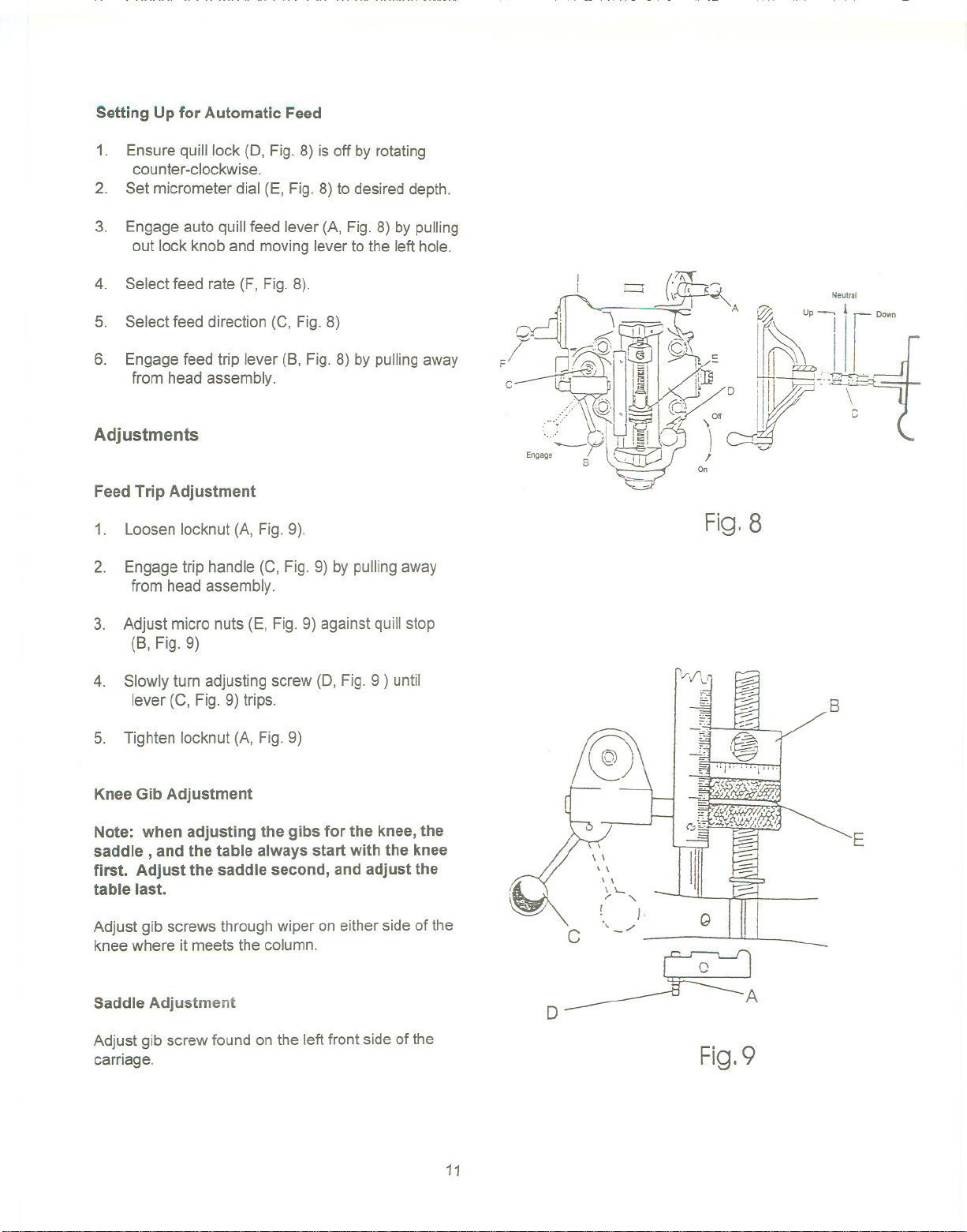
Setting Up for Automatic Feed
1. Ensure quill lock (0, Fig.8) is off by rotating
counter-clockwise.
2. Set micrometer dial (E, Fig. 8) to desired depth.
3. Engageauto quillfeed lever (A, Fig. 8) by pulling
out lock knoband movingleverto the lefthole.
4. Select feed rate(F, Fig.8).
5. Select feed direction (C, Fig. 8)
6. Engagefeed trip lever (8, Fig.8) by pullingaway
from head assembly.
Adjustments
Feed Trip Adjustment
1. Loosen locknut(A, Fig.9).
2. Engagetrip handle (C, Fig. 9) by pulling away
from head assembly.
3. Adjust micro nuts (E, Fig. 9) againstquill stop
(8, Fig. 9)
4. Slowly turn adjusting screw(0, Fig.9 ) until
lever (C, Fig.9) trips.
5. Tighten locknut (A, Fig. 9)
Fig. 8
/\..;
Neutral
?
B
Knee Gib Adjustment
Note: when adjusting the gibs for the knee, the
saddle, and the table always start with the knee
first. Adjust the saddle second, and adjust the
table last.
Adjust gib screws through wiper on either side of the
knee where it meets thecolumn.
Saddle Adjustment
Adjust gib screw found on the left front side of the
carriage.
E
Fig.9
11

Table Adjustment
Adjust gib screws found on the sides of the table
toward the front of the carriage.
Head Alignment
The scale on the ram adapter and for head rotation
(Fig. 10) are guidesonly. Closetolerancework will
requirethe use of a dial indicatorto makesure the
head is90° to the table in the X andY axis. Please
note the table is fitted to be slightlyhigherinthe
front, usuallyabout .0005".
"'t&' 1--
~...~
JET
Fig.1O
-
12

114. i
115
~
iY
13

Parts List for the JTM-1050Turret Mill
Variable Speed Head Assembly
Index Part
No. No.
Description
Size
Qty.
1 .PVS-001 Housing 1
2 PVS-002 Motor Pulley 1
3 TS-1523011'''''''''''''''''''''' SetScrew M6*6 4
4 .PVS-004""""""""""""'" Belt 3830900 1
5 PVS-005 Motor Pulley 1
7 KEY7725 Key 7*7*25 1
8 PVS-008 Motor Pulley Spring 1
9 PVS-D09""'"'''''''''''''''''''' Spring Stop Washer 1
11 PVS-011""""""""""""'" MotorPulley Cover'"'''''''''''''''''''''''''''''''''''''' 1
12 TS-1502051 Hex Socket Cap Screw M5*20 9
13 . PVS-013 Cover ""'" . 1
14 TS-1502041 Hex Socket Cap Screw M5*16 10
15 ..BB-6007ZZ Ball Bearing ..: 6007ZZ 1
16 PVS-016 Dial Cover 1
17 TS-1502081 Hex Socket Cap Screw M5*35 4
18 TS-1503041 Hex Socket Cap Screw M6*16 3
19 PVS-019 Bushing .' 1
20 PVS-D20 Bushing 1
21 .. .PVS-021 Worm . 1
22 """" PVS-D22 Worm Gear """"""""" 1
23 PVS-D23 , Spring Pin "'"'''''''''''''''''''''''''''''''''' 5*10 2
24 PVS-D24 '"'''''''''''''''''''''''' Bushing 2
25 PVS-D25 Dial Control Shaft 1
26 PVS-D26 Spring Pin 3x12 2
27 PVS-027 ""'"'''''''''''''''''''' Dial Wheel 1
28 PVS-D28 """"""""""""'" Wheel Handle 1
29 PVS-D29 Shaft '''''''''''''''''''''''''''''''''' 1
30 PVS-030 Spring Pin 4*35 2
31 PVS-031 """"""'"'''''''''''' Spring Pin 3*25 1
32 PVS-032 '"'''''''''''''''''''''''' Speed Change Chain 1
33 PVS-033 Adjustment Stud 1
34 PVS-034 Sleeve Nut ... 1
35 PVS-D35 """"""""""""'" Adjustment Stud 1
36 PVS-D36 ""'"'''''''''''''''''''' Tilter """""""""""'''''''''''' 1
37 PVS-D37 Bushing 2
38 """" KEY8760 """"""""""""" Key 8*7*60 2
39 PVS-039 Regula1ingScrew 1
40 PVS-040 Spring Pin 4*12 """"""""""""" 1
41 PVS-D41 Washer 1
42 ....PVS-D42""""""""""""'" Support """""""""""" 1
43 BB-601OZZ Ball Bearing 601OZZ 2
44 PVS-044 Drive PulleyAssembly "'''''''''''''''''''''''''''''''' 1
45 .PVS-D45 "'"'''''''''''''''''''''' Steady Pulley 1
46 PVS-Q46 " """""""""""'" Bearing Cover 1
14

47 ..PVS-047 Braka Lining ...1
48 PVS-048 ... Lock Screw , 1
49 .PVS-049 .. , Brake Spring 2
50 PVS-050 Lower Housing Cover 1
51 TS-1503051 Hex Socket Cap Screw M6*20 10
52 PVS-052 Brake Shaft Sleeve ..1
53 PVS-053 Brake Lock Shaft , 1
54 PVS-054 ,... Brake Lock Block 1
55 TS-1503061 Hex Socket Cap Screw M6*25 1
56 PVS-056 Snap Ring S-12 1
58 ..PVS-058 , Brake Finger Pivot Stud.. 1
59 ,PVS-059 """",,"""""""'" Brake Stud 2
60 PVS-060 ". Snap Ring S-8 1
61 PVS-061 Nut 5/8"-18NF 1
62 PVS-062 Timing Belt Pulley 1
63 PVS-063 Timing Belt 225L 100 1
64 PVS-064 Bearing Housing 1
65 BB-6203ZZ . Ball Bearing... ." 6203ZZ 2
66 .." PVS-066 Bull Gear 1
67 PVS-067 ., Counter Shaft 1
68 .." KEY5515 , Key 5*5*15 1
69 KEY5518 Key 5*5*18 1
70 PVS-070 Spindle Pulley Hub " 1
71 .KEY8720 Key 8*7*20 1
72 ..KEY8712 Key " 8*7*12 1
73 PVS-073 Spindle Gear Hub 1
74 ..., PVS-074 , Gear 1
75 PVS-075 " Rack Cup 1
76 PVS-076 Washer 1
77 .BB-6908ZZ Ball Bearing 6908ZZ 2
78 .PVS-078 Bearing Washer " 1
79 PVS-079 Bearing Washer , 1
80 ,...PVS-080 ",,""""""""""'" Snap Ring C-62 1
81 PVS-081 Nut. , 1
82 .PVS-082 Housing 1
84 PVS-084 Spring 3
85 PVS-085 " Vari-Speed Plate " "'''''''''''''''' 1
86 PVS-086 Plastic Face Plate 1
87 .PVS-087 " Gear Shaft Pinion 1
89 PVS-089 Deter Plate ...1
90 .PVS-090 ,.Bearing Stop .. 1
91 PVS-091 Spring .." 1
92 PVS-092 Pinion Block 1
93 TS-1503011 Hex Socket Cap Screw M5*14 2
94 PVS-094 Pinion Crank ,..1
95 PVS-095 Cap Nut 1
96 ., PVS-096 , Nut 3/8" 1
98 PVS-098 Wave Washer 1
99 PVS-099 Plastic Ball .. ...2
100 ..,...PVS-100 Collar , 1
101 .PVS-101 Cover .., ..2
102 PVS-102 .' "" Spring Shaft 3
103 PVS-103 Washer 1
105 PVS-105 RoundHead Screw 3/16"*3/8" 8
15

106 ......PVS-106 Snap Ring '''''''''''''''''''''''''''''''''''''''''' S-28 1
109 PVS-109 LockWasher 1
110 TS1540041 Nut M6 1
111 TS-0209051 Hex Socket Cap Screw 3/8"*1" 2
112 PVS-112 """"""""""""'" Motor '"'''''''''''''''''''''''''''''''''''''''''''''''''''''' """"'"'''''''' 1
113 .PVS-113 Round Head Screw. '''''''''''''''''''''''''''''' '''''''''' 1/8"*1/4" 4
"'" .PVS-114 DrawBar 1
114
115 PVS-115 Draw BarWasher 1
118 PVS-118 ""'"'''''''''''''''''''' HexSocketCapScrew M5*6 1
121 BB-6024ZZ Ball Bearing "''''''''''''''''''''''''''''''''''''''''''''''''" 6204ZZ 1
16

Head Assembly
;;:
2 21
19 0 ~
. 24
~ 23
~
j."- "
192
~
25
17
~
! I
j
tj V'41
Q-133
195 ~
196~@-129
_142 ~
127
140
0 194
~_131
~135
I
s- 137
8--13,
~_135
I
0-- 134

Head Assembly
1 TS-1503031 HexSocket Cap Screw M6*12 1
2 B-2 Washer 1
3 B-3 Feed BevelPinion 1
4 B-4 Worm GearShaft Sleeve 1
5 .B-5 Bushing . , 1
6 TS-1522011 Set Screw , 1
8 ., B-8 Worm Gear 1
10 KEY3312 Key 3*3*12 1
12 TS-1504031 HexSocket Cap Screw M8*16 1
13 B-13... Washer 1
14 KEY3308 Key.. " 3*3*8 2
15 B-15 BevelGear "'''''''''''''''''''''''''''''''' 1
16 B-16 Feed Engage Pin 1
17 B-17 Worm Gear Cradle 1
18 B-18 Worm Gear Cradle Shaft 1
19 8-19 ShaftSleeve 1
20 .8-20 Gear Shaft Plunger ..2
21 ..8-21 Spring 2
22 8-22 Spring Pin 3*20 2
23 8-23
Shift Crank ..2
24 ..8-24. 81ackPlastic8all .. ... 3
25 TS-1503010 HexSocketCap Screw M5x12 3
27 8-27 "'''''''''''''''''''''''''''''''' 8ushing 1
28 8-28 Gear 1
29 ..KEY3345 Key 3*3*45 1
31 .8-31 Gear Shaft 1
32 .. 8-32 Snap Ring S-16 1
33 ...8-33 Bevel Gear Bushing ' 1
34 8-34.. Spacer 1
36 ...8-36.. Gear 1
39 TS-1540031 Nut "'"'''''''''''''''''''''''''''''''''''''''''''' M5 1
40 8-40 Feed Drive Gear '"'''''''''''''''''''''''' , ...1
41 .8-41 Needle Bearing .""""""""'''''''''''''''''''''' 1
42 . .8-42 Bushing ... 1
43 ...8-43 Worm Gear 1
44 8-44 8ushing 1
47 ..8-47 Washer 1
48 .8-48 , ,., 8ushing..., , , ,2
49 .8-49 8evel Gear .., , , , """'" ..2
50 8-50... Feed Reverse Clutch 1
54 TS-1503061 Hex SocketCap Screw M6*25 1
55 .. .8-55 Reverse Clutch Rod 1
56 8-56 Spring Pin 3*20 1
57 ..8-57 Feed Worm Shaft 1
58 TS-1523011 Set Screw M6*6 1
59 8-59 Spring Pin 3*12 2
60 ...B-60... Chip Guards 1
61 TS-1522031 Set Screw M5*10 1
62 ..KEY3315 """'''''''' Key 3*3*15 ,.. 2
63 8-63 Feed Gear Shift Fork 1
64 8-64 Gear Shift Crank 1
66 .8-66.. Cluster Gear Cover "'" ...1
18

87 TS-1502031 Hex SocketCap Screw M5*12 A
73 .TS-1502081 , Hex SocketCap Screw M5*35 2
74 8-74 Clutch Ring Pin... ,.. 2
75 8-75 Clutch Ring 1
78 TS-1523021 Set Screw M6*8 1
78 ...8-78 Clutch Locknut 1
79 8-79 ..., SafetyClutch Locknut 1
80 8-80 Overload Clutch 1
81 8-81 OverloadClutchSleeve , 1
82 .KEY5813 Key 5*8*13 1
83 8-83 ,..Hex Socket Head 8olt 3
85 .TS-1523011 Set Screw M6*6 2
86 8-86 Cross PlateScrew M4*16 4
88 8-88 ". Spring , 1
89 8-89 Spring Plunger 1
90 .8-90 8ushing 1
92 ..8-92 Worm Gear 1
93 8-93 Clutch Ring 1
94 ..8-94 Snap Ring S-10 1
95 TS-1502051 Hex Socket Cap Screw M5*20 1
96 8-96 Clutch Trip Lever"""""""""""""""""""'''''' 1
97 8-97 Clutch Washer 1
98 8-98 Snap Ring S-10 1
99 8-99 Clutch Arm Cover 1
100 "C-19-1 SetScrew M6*16 1
101 TS-1540041 Nut " M6 1
102 .8-102 Spring Pin 5*18 . , 1
103 8-103 Cam Rod... 1
104 8-104 Trip Handle " 1
106 ..8-106 FeedTrip 8racket 1
107 TS-1503051 Hex Socket Cap Screw M6*20 1
108 TS-1523031 Set Screw M6*10 1
109 KEY3310 Key 3*3*10 1
110 .8-110 Knob Stud 1
111 8-111 Reverse Knob 1
112 8-112 E-Ring " E-6 1
113 8-113 , HandleWheel Clutch 1
114 8-114.. Steel 8all ,... 3/16" 2
115 8-115 ,CompressionSpring 2
116 ..8-116 Set Screw.. M8*6 1
117 ......8-117 Spring Pin 3*15 1
118 8-118 Cam RodSleeve 1
119 8-119 Spring Pin 3*12 1
120 ......8-120 CompressionSpring 1
121 8-121 Trip Plunger 1
123 .8-123 Bushing ,... 4
124 8-124 Feed Trip Plunger 1
125 8-125 Handle Wheel 1
126 8-126 Handle 1
127 8-127 .Spindle , 1
128 8-128 Quill Skirt 1
129 ..8-129 Locknut 1
131 88-6206ZZ 8all 8earing .. " 6206ZZ " 1
19

132 .B-132... Nut """"'" M4 1
133 B-133 Nose Piece 1
134 B-134 Spindle Dirt Shield 1
135 ..:...BB-7207C. Angular Bearing 7207.. 1
136 B-136 Spacer 1
137 B-137"""""'" Spacer 1
138 BB-7207C Angular Bearing '"'''''''''''''''''''''''''''''''''''''''''' 7207 1
139 B-139 Set Screw 1
140 B-14O Set Screw 1
141 .TS-1523011.., Set Screw M6*6 1
142 B-142 " Quill ""'''''''''''''''''''''''''''''''''''''''''''''''''''''''''''' 1
143 ..B-143 Spring Pin 3*16 1
144 ..B-144 Set Screw M4*20 1
145... ...B-145 FeedTrip Lever 1
146 .". ..B-146 Trip Lever Pin 1
147 .B-147 , Indicator Rod 1
148 B-148 Quill LockSleeve 1
149 B-149 Lock Handle 1
150 ......B-150 .". Round HeadScrew M5*8 2
151 B-151 Washer M5 2
153 .. B-153 Quill LockSleeve 1
154 B-154. Indicator Rod Screw.. 1
155 B-155 T-Bolt 4
156 ., B-156 Spacer : 4
157 B-157"""""""""""""""" Adaptor Nut 4
158 B-158 """"""""""""" Round Head Screw 2
159 .B-159 MicrometerScale 1
160 B-160 Snap Ring S-16 1
161 B-161
162 B-162 Quill Micro-Stop Nut '"'''''''''''' """'''''''''' 1
163 B-163 Quill Stop Knob 1
164 B-164 Quill Micro-Stop Nut 1
165 B-165. Round Head Screw M10*15 1
166 B-166 Quill Pinion Shaft 1
168 .B-168 Pin 1
169 TS-1503010.. HexSocketCap Screw M5*12 2
171 .KEY3320 Key 3*3*20 1
172 B-172 '''''''''''''''''''''''''''''''' Pinion Shaft Hub Screw 1
173 B-173 Set Screw 5/16"*1/4" 1
174 ......B-174 CompressionSpring , ... "" ""'" ... ... ... 1
175 B-175 Handle Hub 1
176 ......B-176 Hub Sleeve .. 1
177 "'" .B-177 Spring Cover 1
178 .B-178 Clock Spring 1
179 .B-179 Washer , 4
181 TS-1523041 Set Screw ... M6*12 2
183 B-183 ". ReverseTrip Ball Lever 1
184 B-184 ReverseTrip Plunger.. 1
185 B-185 Trip Ball Lever Screw 1
186 B-186 Worm Gear 1
187 ..KEY4418 Key 4*4*18 1
188 B-188 Set Screw """"""'" 1
189 .B-189 Worm Shaft ""'''''''''''''''''''''' 1
190 B-190 Pinion ShaftHub Handle"""""""'''''''''''''''''' 1
Quill Micro-Stop Nut 1
20

191 B-191 BlackPlasticBall 1
192 ...,..B-192 , , Quill Housing 1
193 B-193 CompressionSpring 1
194 B-194 SnapRing S-30 ..1
195 B-195 Bush 1
196 TS-1523011 Set Screw , M6*6 1
197 B-197"",""""""""""""'" Nut 1
21

Base Assembly
! I 10
22
94
/191
9
""
I / 95
/ / / 96
.~~
'-"9-,

Base Assembly
1 C-1 Worm Washer 1
2 . ...C-2 RamAdaptor...'"'''''''''''''''''''''''' ... 1
3 C-3 , Adaptor Scale 1
4 C-4 , Lock Nut ... ..1
6 ". C-6... Worm Gear """'" "'"'''''' 1
7 C-12 .. ................ Collar 1
8 .C-8 Worm Shaft ...1
9 ..KEY5550 Key 5*5*50 1
10 C-10 Ram 1
11 C-11 Hook 3/4" 1
12 .. C-7-1 , Washer . "'"'''''''' 1
13 TS-1504061 HexSocket Cap Screw M8*30 2
14 C-14 Spring Pin '"'''''''''''''''''''' 1
15 .., C-15 Angle Plate " 1
16 C-16 Rivet ""'"'''''''''' 10
17 C-17 Adaptor Pivot Stud 1
18 .C-18 " Washer , .., """" 3
19 C-19 Locking Bolt. "'''''''''''''''''' 3
23 C-23 Table 1
31 C-31 T-Bolt 2
32 ..C-32 Table Stop Piece 2
33 C-33 Hex Nut 3/8" -16NC ,2
34 C-34 Chip Guard ..." ' 1
36 C-36 Pan Head Screw 3/16"*3/8" 4
38 ...C-38A Saddle Lock Bolt "'''''''''''''''''''''''''''''''''''''' . 5
39 C-39 Saddle Lock Plunger.. 1
40 C-40 Hex Socket Cap Screw 2
41 C-41 , Adjusting Screw 10
42 C-42 Table Stop Bracket 1
43 C-43 Gib 1
46 . C-46 Table Lock Plunger 4
49 C-49 Saddle Knee Gib ..." 1
50 C-50-1 Wiper ,...2
51 C-51 Pan Head Screw 18
52 C-52 Saddle.., 1
54 C-54 Knee Wiper Felt , 1
55 C-55 Knee Column Gib , 1
58 .C-58 Knee Wiper Felt 1
60 C-60 Chip Guards , , 1
61 C-61 Chip Guards ""'''''''''''''''''''''''''''''''''''''''''''''' 1
62 C-62 ..., Chip Guards " 1
63 C-63 Chip Guards . 1
64 C-64 Knee '''''' 1
71 C-71 Pan Head Screw """""" 8
72 ".C-72 Cover 1
73 .C-23-1 Washer.. """ 1
74 C-74 , Nut 112"-20NF,., 1
75 ..KEY5525 ..., Key "'''''''''''''''''''' 5*5*25 1
76 C-76 Washer 1
77 ,..C-77 Bevel Gear 1
78 ..C-78... Front Cover , 1
79 BB-5305ZZ " Ball Bearing 5305 1
23

80 C-80 Bearing Stop 1
81 TS-1503051 Hex Socket CapScrew M6*20 3
82 C-82 Leadscrew """"""""""""""""""""""""""" 1
83 C-83 Handle 1
84 .""'" C-84 ElevatingCrank 1
85 C-85 Gear ShearClutch 1
86"""" C-86 Dial Lock Nut '"'''''''''''''''''''''''''''''''''''' 1
87 C-87 Dial """"'''''''''''''''''''''''''' 1
88 C-88 Dial Holder 1
89 TS-1503051 HexSocket CapScrew M6*20 3
90 C-90 Bearing Stop """""""""""'" 1
91 BB-6204ZZ Ball Bearing '"'''''''''''''.''''''''''''''''''''''''''''''''''' 6204ZZ 2
92 C-92 Bearing Stop ...1
93 KEY3318 Key 3*3*18 1
94 C-94 Shaft 1
95 C-95 Grub Set Screw 1
96 C-96 Bevel Gear. 1
97 ...KEY4418 Key... 4*4*18 1
98 """" C-98 Column 1
100 C-19-1 Collar 1
102 TS-1505051 HexSocket Cap Screw M10*35 2
103 C-103 Lead ScrewHousing.., 1
104 C-82-1 Lead Screw Nut 1
105 TS-1503051 Hex SocketCap Screw M6*20: 3
108 C-38A """""""'"'''''''''''''' Lock Bolt 2
109 C-109 Nut 3/8" 2
110 C-110 Set Screw 2
111 C-111 Gib 1
112 C-112 Gib Holder(L)"'''''''''''''''''''''''''''''''''''''''''''''''' 1
113 C-113 """"'"'''' Gib """"'''''''''''''''''''''''''' 1
114 C-114 Gib Holder(R) 1
115 TS-1505051 Hex SocketCap Screw M10*35 8
118 C-118 Spider """"""""""""" ,1
120 ......C-120 ""'" RamPinion 1
123 C-123 Spring Washer 4
124 C-124 Turret 1
126 C-126 Ram LockPlunger "'"'''''''''''''''''' 2
127 .,....C-127 Locking Bolt ,.4
128 C-128 Ram Pinion Set Screw 1
129 C-129 Rivet 2
130 C-130 Strainer --""""'" -- 1
131. JM-1050 ... Stripe Decal (Not Shown) 1
24

r-
C'D
m
a.
N
(]'I
(J)
(1
""'(
CD
:E
»
(J)
(J)
(D
21
3
0"'
'<
14
9
20
6

leadscrew Assembly
1 0-1. Nut ..,"" ,..... 1/2»-20NF "'" 3
2 0-2. Handle 3
3 .0-3 Ball Crank 3
4 ..........0-4 ..,... ..., ,... Dial Lock Nut.. ... ...3
5 0-5 Dial 3
6 .. 0-6 Dial Holder... ... , ... .. 3
7 TS-1503031 '"'''''' Hex Socket Cap Screw M6*12 9
8 C-90 Bearing Stop 3"
9 ...BB-6204ZZ Ball Bearing 6204ZZ 5
10 0-10 Bearing Bracket 2
11 0-11 Spring Pin '"'''''''''''''''''''''''''''''''''''''''''''''''''''' 5*25 6
12 TS-1505031 HexSocket Cap Screw ... 16
13 KEY3325 Key 3*3*25 3
14 0-14 Leadscrew ... , 1
15 TS-1503061 Hex Socket Cap Screw 10
16 H-9 Washer 4
17 . 0-17 ... Feed Screw Nut . ... 2
18 0-18 Feed Nut Bracket 1
20 0-20 Cross Bearing Bracket 1
21 0-21 Cross Feed Screw 1
22 .. .0-22... Cross Feed Nut """ ,.. 2
23 .. .0-23 Spring Washer """""" 1/2» 3
26

8 9
7
,
3
1
6
3
4
12
11
1
One Shot Lubrication System
1 CLA-8 ...-.... Handle Oiler .. 1
2 ALMP-04 AluminumPiece ..., 13.5mm. 1
3 A-8 OilRegulation Distributor 1
4 ..A-4 OilRegulation Distributor 1
5 .A-5 '.""'''''' FlexibleSteel Tube 4*550 1
6 PH-4011 ElbowJoint ... 2
7 PI-401 ElbowJoint 6
8 ,..PA-4 ThimbleNut .20
9 PB-4 Thimble .20
10 PG-004 , Union , 1
11 .JTM4VS-BUTW1458 Screw , M6*14 4
12 ..TS-1502061 Hex Socket Cap Screw M5*25 4
13 PD-401 Straight Joint .. 1
14 .A-14 'Nylon Piece 4*700 1
27

Electrical Sche,matic
Switch
For 230 V
-
Power
@ @
(j)
@
U1 V1 W1
@)
CD
For460V
@
@
U1
Power
I
@
(0
V1
CD
@J
W1
Motor
? 9 ?
U2 V2 W2
666
x
y
z
28
6
6
6
U2 V2 W2
x
y z


 Loading...