

JET JTM-1050EVS2/230, JTM-949EVS, JTM-949EVS/230 Operating Instructions and Parts Manual

This .pdf document is bookmarked
Operating Instructions and Parts Manual
Electronic Variable Speed Turret Mill
Models: JTM-949EVS/230, JTM-949EVS4
JTM-1050EVS2, JTM-1050EVS4
JTM-949EVS/230 shown
JET
427 New Sanford Road
LaVergne, Tennessee 37086 Part No. M-690501
Ph.: 800-274-6848 Revision G 10/2019
www.jettools.com Copyright © 2018 JET

1.0 Warranty and service
JET warrants every product it sells against manufacturers’ defects. If one of our tools needs service or repair, please
contact Technical Service by calling 1-800-274-6846, 8AM to 5PM CST, Monday through Friday.
Warranty Period
The general warranty lasts for the time period specified in the literature included with your product or on the official
JET branded website.
JET products carry a limited warranty which varies in duration based upon the product. (See chart below)
Accessories carry a limited warranty of one year from the date of receipt.
Consumable items are defined as expendable parts or accessories expected to become inoperable within a
reasonable amount of use and are covered by a 90 day limited warranty against manufacturer’s defects.
Who is Covered
This warranty covers only the initial purchaser of the product from the date of delivery.
What is Covered
This warranty covers any defects in workmanship or materials subject to the limitations stated below. This warranty
does not cover failures due directly or indirectly to misuse, abuse, negligence or accidents, normal wear-and-tear,
improper repair, alterations or lack of maintenance. JET woodworking machinery is designed to be used with Wood.
Use of these machines in the processing of metal, plastics, or other materials outside recommended guidelines may
void the warranty. The exceptions are acrylics and other natural items that are made specifically for wood turning.
Warranty Limitations
Woodworking products with a Five Year Warranty that are used for commercial or industrial purposes default to a
Two Year Warranty. Please contact Technical Service at 1-800-274-6846 for further clarification.
How to Get Technical Support
Please contact Technical Service by calling 1-800-274-6846. Please note that you will be asked to provide proof
of initial purchase when calling. If a product requires further inspection, the Technical Service representative will
explain and assist with any additional action needed. JET has Authorized Service Centers located throughout the
United States. For the name of an Authorized Service Center in your area call 1-800-274-6846 or use the Service
Center Locator on the JET website.
More Information
JET is constantly adding new products. For complete, up-to-date product information, check with your local distributor
or visit the JET website.
How State Law Applies
This warranty gives you specific legal rights, subject to applicable state law.
Limitations on This Warranty
JET LIMITS ALL IMPLIED WARRANTIES TO THE PERIOD OF THE LIMITED WARRANTY FOR EACH PRODUCT.
EXCEPT AS STATED HEREIN, ANY IMPLIED WARRANTIES OF MERCHANTABILITY AND FITNESS FOR A
PARTICULAR PURPOSE ARE EXCLUDED. SOME STATES DO NOT ALLOW LIMITATIONS ON HOW LONG AN
IMPLIED WARRANTY LASTS, SO THE ABOVE LIMITATION MAY NOT APPLY TO YOU.
JET SHALL IN NO EVENT BE LIABLE FOR DEATH, INJURIES TO PERSONS OR PROPERTY, OR FOR
INCIDENTAL, CONTINGENT, SPECIAL, OR CONSEQUENTIAL DAMAGES ARISING FROM THE USE OF OUR
PRODUCTS. SOME STATES DO NOT ALLOW THE EXCLUSION OR LIMITATION OF INCIDENTAL OR
CONSEQUENTIAL DAMAGES, SO THE ABOVE LIMITATION OR EXCLUSION MAY NOT APPLY TO YOU.
JET sells through distributors only. The specifications listed in JET printed materials and on official JET website are
given as general information and are not binding. JET reserves the right to effect at any time, without prior notice,
those alterations to parts, fittings, and accessory equipment which they may deem necessary for any reason
whatsoever. JET
Product Listing with Warranty Period
90 Days – Parts; Consumable items
1 Year – Motors; Machine Accessories
2 Year – Metalworking Machinery; Electric Hoists, Electric Hoist Accessories; Woodworking Machinery used
for industrial or commercial purposes
5 Year – Woodworking Machinery
Limited Lifetime – JET Parallel clamps; VOLT Series Electric Hoists; Manual Hoists; Manual Hoist
Accessories; Shop Tools; Warehouse & Dock products; Hand Tools; Air Tools
NOTE: JET is a division of JPW Industries, Inc. References in this document to JET also apply to JPW Industries,
Inc., or any of its successors in interest to the JET brand.
®
branded products are not sold in Canada by JPW Industries, Inc.
2

2.0 Table of contents
Section Page
1.0 Warranty and service ..................................................................................................................................... 2
2.0 Table of contents ............................................................................................................................................ 3
3.0 Safety warnings .............................................................................................................................................. 5
4.0 About this manual .......................................................................................................................................... 6
5.0 Specifications ................................................................................................................................................. 7
5.1 Machine dimensions – JTM-949EVS and JTM-1050EVS series ............................................................... 8
5.2 Overview and terminology – JTM-949EVS and JTM-1050EVS series ...................................................... 9
6.0 Set-up and assembly ................................................................................................................................... 10
6.1 Contents of shipping container ................................................................................................................. 10
6.2 Preparing the mill for service .................................................................................................................... 10
7.0 Electrical connections .................................................................................................................................. 11
7.1 General electrical cautions ....................................................................................................................... 11
7.2 Wire sizes ................................................................................................................................................. 11
8.0 Lubrication .................................................................................................................................................... 12
9.0 Operating instructions .................................................................................................................................. 12
9.1 Operating controls .................................................................................................................................... 12
9.2 Control panel ............................................................................................................................................ 12
9.3 Control positions for milling and drilling operations .................................................................................. 13
9.4 Electronic variable speed ......................................................................................................................... 14
9.5 Spindle brake ........................................................................................................................................... 14
9.6 High-neutral-low shift lever ....................................................................................................................... 14
9.7 Quill power feed lever ............................................................................................................................... 14
9.8 Feed rate lever ......................................................................................................................................... 14
9.9 Feed trip cam lever ................................................................................................................................... 15
9.10 Feed direction control ............................................................................................................................. 15
9.11 Coarse feed handle ................................................................................................................................ 15
9.12 Quill lock handle ..................................................................................................................................... 15
9.13 Micrometer adjusting nut ........................................................................................................................ 15
9.14 Fine feed handwheel .............................................................................................................................. 16
9.15 Depth scale and stop .............................................................................................................................. 1 6
9.16 Power feed operation ............................................................................................................................. 16
9.17 Draw bar operation – changing tooling ................................................................................................... 17
9.18 Clamping workpiece to table .................................................................................................................. 17
10.0 Adjustments ............................................................................................................................................... 17
10.1 Mill head – left/right adjustment .............................................................................................................. 17
10.2 Mill head – fore/aft adjustment ............................................................................................................... 18
10.3 Positioning ram ....................................................................................................................................... 18
10.4 Gib adjustment ....................................................................................................................................... 19
10.5 Power feed trip lever mechanism .......................................................................................................... 19
10.6 Table lead screw backlash adjustment .................................................................................................. 20
11.0 Maintenance ............................................................................................................................................... 21
11.1 Lubrication .............................................................................................................................................. 21
11.2 Periodic maintenance requirements ....................................................................................................... 21
12.0 Recommended speed for mill and drill operations ..................................................................................... 22
13.0 Replacement parts ..................................................................................................................................... 22
13.1.1 JTM-949EVS/JTM-1050EVS Upper Head Assembly – Exploded View ............................................. 23
13.1.2 JTM-949EVS/JTM-1050EVS Upper Head Assembly – Parts List ...................................................... 24
13.2.1 JTM-949EVS/JTM-1050EVS Lower Head Assembly – Exploded View ............................................. 26
13.2.2 JTM-949EVS/JTM-1050EVS Lower Head Assembly – Parts List ...................................................... 27
13.3.1 JTM-949EVS Base Machine – Exploded View .................................................................................. 30
13.3.2 JTM-949EVS Base Machine – Parts List ........................................................................................... 31
13.4.1 JTM-1050EVS Base Machine – Exploded View ................................................................................ 33
13.4.2 JTM-1050EVS Base Machine – Parts List ......................................................................................... 34
13.5.1 JTM-949EVS Table Assembly – Exploded View ................................................................................ 36
13.5.2 JTM-949EVS Table Assembly – Parts List ........................................................................................ 37
13.6.1 JTM-1050EVS Table Assembly – Exploded View .............................................................................. 38
13.6.2 JTM-1050EVS Table Assembly – Parts List ...................................................................................... 39
13.7.1 JTM-949EVS/JTM-1050EVS Control Panel Assembly – Exploded View .......................................... 40
3

13.7.2 JTM-949EVS/JTM-1050EVS Control Panel Assembly – Parts List ................................................... 40
13.8.1 JTM-949EVS/JTM-1050EVS Electrical Box – Exploded View ........................................................... 41
13.8.2 JTM-949EVS/JTM-1050EVS Electrical Box – Parts List .................................................................... 41
13.9.1 JTM-949EVS/JTM-1050EVS Coolant Pump (Optional) – Exploded View ......................................... 42
13.10.1 JTM-949EVS/JTM-1050EVS Work Lamp – Exploded View ............................................................ 42
13.9.2 JTM-949EVS/JTM-1050EVS Coolant Pump (Optional) – Parts List .................................................. 42
13.10.2 JTM-949EVS/JTM-1050EVS Work Lamp – Parts List ..................................................................... 42
13.11.1 JTM-949EVS/JTM-1050EVS Spindle Guard Assembly – Exploded View ....................................... 43
13.11.2 JTM-949EVS/JTM-1050EVS Spindle Guard Assembly – Parts List ................................................ 43
13.12.1 JTM-949EVS Lubrication System – Exploded View ......................................................................... 44
13.12.2 JTM-949EVS Lubrication System – Parts List ................................................................................. 44
13.13.1 JTM-1050EVS Lubrication System Assembly – Exploded View ...................................................... 45
13.13.2 JTM-1050EVS Lubrication System Assembly – Parts List ............................................................... 4 5
14.0 Electrical Connections ................................................................................................................................ 46
14.1 JTM-949EVS/230 and JTM-1050EVS2 (230V ONLY) ........................................................................... 46
14.1 JTM-949EVS4 and JTM-1050EVS4 (460V ONLY) ................................................................................ 47
4

3.0 Safety warnings
1. Read and understand the entire owner's
manual before attempting assembly or
operation.
2. Read and understand the warnings posted on
the machine and in this manual. Failure to
comply with all of these warnings may cause
serious injury. Replace warning labels if they
become obscured or removed.
3. This turret mill is designed and intended for use
by properly trained and experienced personnel
only. If you are not familiar with the proper and
safe operation of a turret mill do not use until
proper training and knowledge have been
obtained.
4. Do not use this turret mill for other than its
intended use. If used for other purposes, JET
disclaims any real or implied warranty and holds
itself harmless from any injury that may result
from that use.
5. Always wear approved safety glasses/face
shields while using this turret mill. Everyday
eyeglasses only have impact resistant lenses;
they are not safety glasses.
6. Before operating this turret mill, remove tie,
rings, watches and other jewelry, and roll
sleeves up past the elbows. Do not wear loose
clothing. Confine long hair. Non-slip footwear or
anti-skid floor strips are recommended. Do not
wear gloves.
7. Wear ear protectors (plugs or muffs) during
extended periods of operation.
8. Do not operate this machine while tired or under
the influence of drugs, alcohol or any
medication.
9. Make certain the switch is in the OFF position
before connecting the machine to the power
supply.
10. Make certain the machine is properly grounded.
11. Make all machine adjustments or maintenance
with the machine unplugged from the power
source.
12. Remove adjusting keys and wrenches. Form a
habit of checking to see that keys and adjusting
wrenches are removed from the machine
before turning it on.
13. Keep safety guards in place at all times when
the machine is in use. If removed for
maintenance purposes, use extreme caution
and replace the guards immediately after
completion of maintenance.
14. Check damaged parts. Before further use of the
machine, a guard or other part that is damaged
should be carefully checked to determine that it
will operate properly and perform its intended
function. Check for alignment of moving parts,
binding of moving parts, breakage of parts,
mounting and any other conditions that may
affect its operation. A guard or other part that is
damaged should be properly repaired or
replaced.
15. Do not use power tools in damp/wet locations
or other dangerous environments.
16. Do not expose them to rain. Provide for
adequate space surrounding work area and
non-glare, overhead lighting.
17. Keep the floor around the machine clean and
free of scrap material, oil and grease.
18. Keep visitors a safe distance from the work
area. Keep children away. Workshop should be
child proof with padlocks, master switches or by
removing starter keys.
19. Give your work undivided attention. Looking
around, carrying on a conversation and “horseplay” are careless acts that can result in serious
injury.
20. Maintain a balanced stance at all times so that
you do not fall against cutters or other moving
parts. Do not overreach or use excessive force
to perform any machine operation.
21. Use the right tool at the correct speed and feed
rate. Do not force a tool or attachment to do a
job for which it was not designed. The right tool
will do the job better and more safely.
22. Use recommended accessories; improper
accessories may be hazardous.
23. Maintain tools with care. Keep cutters sharp
and clean for the best and safest performance.
Follow instructions for lubricating and changing
accessories.
24. Turn off the machine before cleaning. Use a
brush or compressed air to remove chips or
debris — do not use your hands.
25. Do not stand on the machine. Serious injury
could occur if the machine tips over.
26. Never leave the machine running unattended.
Turn the power off and do not leave the
machine until it comes to a complete stop.
27. Remove loose items and unnecessary work
pieces from the area before starting the
machine.
5

28. Clamp workpiece or brace against column to
prevent rotation. For safety and use of both
hands, use clamps or a vise to hold work.
29. Use recommended speed for cutter/drill
accessory and workpiece material.
30. Direction of feed – feed work into a blade or
cutter against the direction of rotation of the
blade or cutter only.
31. Installation work and electrical wiring must be
done by a qualified electrician in accordance
with all applicable codes and standards.
WARNING: This product can expose you to
chemicals including lead and cadmium which
are known to the State of California to cause
cancer and birth defects or other reproductive
harm, and phthalates which are known to the
State of California to cause birth defects or other
reproductive harm. For more information go to
http://www.p65warnings.ca.gov.
Familiarize yourself with the following safety notices used in this manual:
WARNING: Some dust, fumes and gases
created by power sanding, sawing, grinding,
drilling, welding and other construction activities
contain chemicals known to the State of
California to cause cancer and birth defects or
other reproductive harm. Some examples of
these chemicals are:
lead from lead based paint
crystalline silica from bricks, cement and
other masonry products
arsenic and chromium from chemically
treated lumber
Your risk of exposure varies, depending on how
often you do this type of work. To reduce your
exposure to these chemicals, work in a wellventilated area and work with approved safety
equipment, such as dust masks that are
specifically designed to filter out microscopic
particles. For more information go to
http://www.p65warnings.ca.gov/ and http://www.
p65warnings.ca.gov/wood.
This means that if precautions are not heeded, it may result in minor injury and/or possible
machine damage.
This means that if precautions are not heeded, it may result in serious, or even fatal, injury.
4.0 About this manual
This manual is provided by JET, covering the safe operation and maintenance procedures for JET Model JTM949EVS series and JTM-1050EVS series Turret Mills. This manual contains instructions on installation, safety
precautions, general operating procedures, maintenance instructions and parts breakdown. Your machine has
been designed and constructed to provide consistent, long-term operation if used in accordance with the
instructions as set forth in this document.
If there are questions or comments, please contact your local supplier or JET. JET can also be reached at our
web site: www.jettools.com.
Retain this manual for future reference. If the machine transfers ownership, the manual should accompany it.
Read and understand the entire contents of this manual before attempting assembly or
operation! Failure to comply may cause serious injury!
Register your product using the mail-in card provided, or register online:
http://www.jettools.com/us/en/service-and-support/warranty/registration/
6

5.0 Specifications
Table 1
Model number
Stock number 691500 690701 691600 690801
Motor and Electricals
Motor type TEFC
Horsepower 3 HP (2.24 kW)
Phase 3
Voltage 230 460 230 460
Cycle 60 Hz
Listed FLA (full load amps) 8 A 4 A 8 A 4 A
Motor speed 1720 RPM
Power transfer Pulley/gears
Sound emission1
Head and Spindle
Spindle taper R8
Diameter of quill 3.375 in. (85.75 mm)
Number of spindle speeds variable
Range of spindle speeds 60-500 / 500-4500 RPM
Downfeeds per revolution of
spindle
Spindle travel 5 in. (127 mm)
Head movement, left and right 90 deg.
Head movement, fore and aft
Spindle nose to table,
Maximum distance
Spindle center to column,
Maximum distance
Spindle center to column
Minimum distance
Collet capacity 1/8 to 7/8 in.
Ram travel, maximum 8-1/8 in. (206 mm) 17-3/8 in. (440 mm)
Table and Knee
Table size 9 x 49 in. (229 x 1245 mm) 10 x 50 in. (250 x 1270 mm)
Longitudinal table travel, max. 30-3/4 in. (784 mm) 29-7/8 in. (760 mm)
Table cross travel, max. 12 in. (305 mm) 14-3/4 in. (375 mm)
Number of T-slots 3
T-slot size (width x depth) 5/8 x 3/4 in. (15.9 x 19 mm)
T-slot centers 2-1/2 in. (63.5 mm)
Table load, max. 660 lbs. (300 kg) 840 lbs. (380 kg)
Knee travel, max. 15-3/4 in. (402 mm) 16-1/8 in. (412 mm)
Misc. Dimensions
Saddle width 20 in. (510 mm)
Column width 11-3/8 in. (290 mm)
Overall dimensions, assembled 65-3/4 W x 63 D x 85-3/4 H in.
Weights
Net weight, approx. 2420 lb. (1100 kg) 2486 lb. (1130 kg)
Shipping weight, approx. 2552 lb. (1160 kg) 2618 lb. (1190 kg)
1
The specified values are emission levels and are not necessarily to be seen as safe operating levels. As workplace
conditions vary, this information is intended to allow the user to make a better estimation of the hazards and risks
involved only.
Without load 72 dB (at 3.28 ft. from machine)
With load 80 dB (at 3.28 ft. from machine)
JTM-949EVS/230 JTM-949EVS4 JTM-1050EVS2/230 JTM-1050EVS4
0.0015, 0.003, 0.006 in
45 deg.
20-3/4 in. (530 mm)
18-1/8 in. (460 mm) 26-3/4 in. (681 mm)
5.2 in. (132 mm) 5.9 in. (150 mm)
(1670 x 1600 x 2178 mm)
7

The specifications in this manual were current at time of publication, but because of our policy of continuous
improvement, JET reserves the right to change specifications at any time and without prior notice, without incurring
obligations.
5.1 Machine dimensions – JTM-949EVS and JTM-1050EVS series
Figure 1: Installation Diagram (JTM-949EVS/230 shown)
8

5.2 Overview and terminology – JTM-949EVS and JTM-1050EVS series
Figure 2: Overview (JTM-949EVS/230 shown)
9
Read and understand the
entire contents of this manual before attempting
set-up or operation. Failure to comply may
cause serious injury.
6.0 Set-up and assembly
Open shipping container and check for shipping
damage. Report any damage immediately to your
distributor and shipping agent. Do not discard any
shipping material until the Turret Mill is assembled
and running properly.
Compare the contents of your container with the
following parts list to make sure all parts are intact.
Missing parts, if any, should be reported to your
distributor. Read the instruction manual thoroughly
for assembly, maintenance and safety instructions.
If your mill is supplied with an optional Table
Powerfeed and/or DRO, be sure to consult the
separate instruction materials that accompany
them.
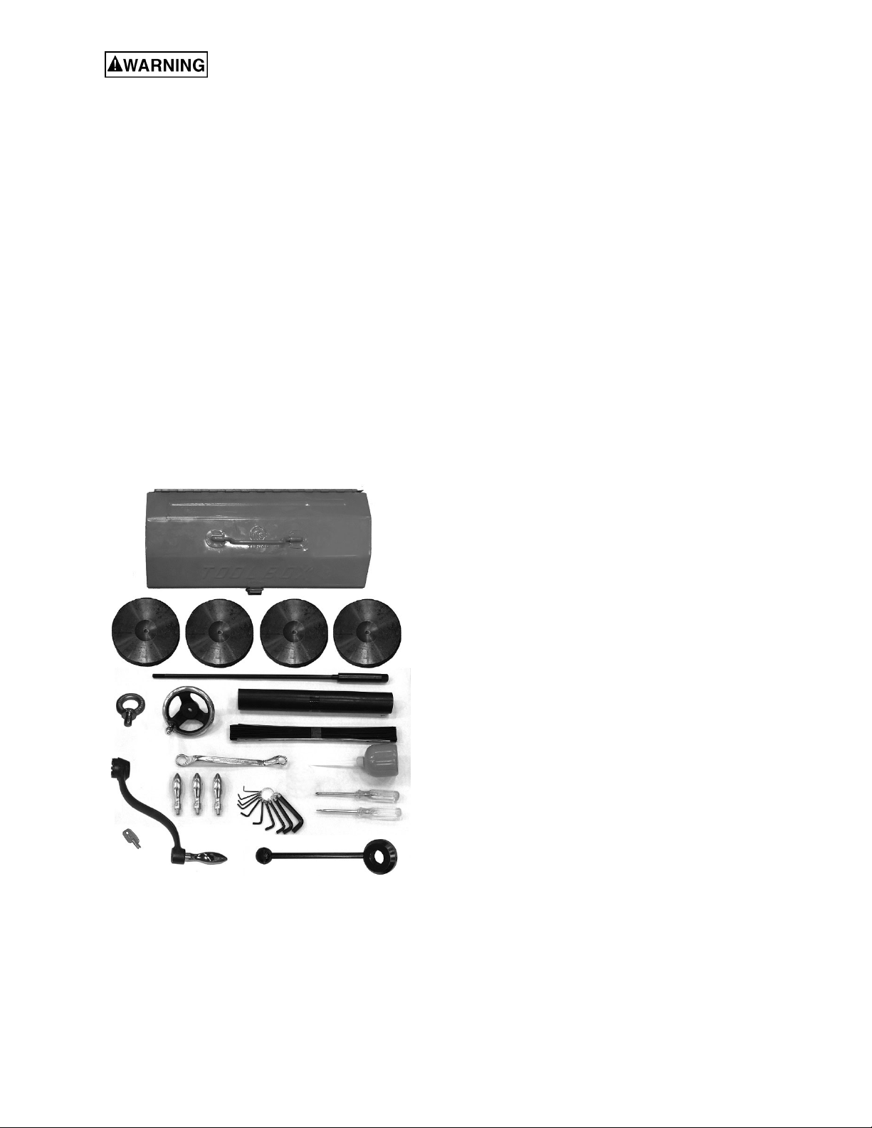
6.1 Contents of shipping container
Note: Some parts may be pre-installed on the mill.
Figure 1: contents
1 Turret Mill (not shown)
1 Chip tray (not shown)
1 Flat Way Cover
1 Pleated Way Cover
1 Draw Bar
3 Table Adjustment Handles
1 Tool Box, containing:
4 Leveling pads
1 Hex Key Set (1.5-10mm) *
1 17/19mm Box Wrench *
1 Cross Point Screw Driver #2 *
1 Flat Blade Screw Driver #2 *
1 Oil Can *
1 Elevating Crank Handle
1 Handwheel
1 Coarse Feed Handle
1 Lifting ring
1 Electric box key
1 Operator’s Manual
1 Product Registration Card
* parts with asterisk are also included in tool box
service kit JTM949EVS-TB or JTM1050EVS2-TB.
6.2 Preparing the mill for service
1. Remove any crating which may be covering the
machine on the pallet.
2. Remove accessory items from the pallet or
machine table. Compare items with section 6.1.
3. Install provided lifting ring into tapped hole atop
ram. (Note: If your mill came with a topmounted DRO, remove DRO from hole to install
lifting ring. Reinstall DRO after machine has
been positioned.) Check lifting ring to be
certain it is tight.
4. Check the tightness of the lock handles on the
ram (see Figure 21) to be certain the ram is
locked tight.
5. Remove the nuts and/or bolts, which secure the
machine to the pallet.
6. Center an overhead crane or other suitable
overhead lifting device and sling arrangement
over the lifting ring.
Note: This machine weighs over 2200 pounds
– Be certain lifting arrangement is new or in
excellent condition and has a safety factor that
will account for age, difficulties in lifting, etc.
When lifting using the ring, the machine will tip
forward. If you wish, you can minimize this
tipping by rigging a support sling over front of
machine. Be careful when doing this, to prevent
sling from damaging any components on front
of machine. Be sure to steady mill to prevent it
from spinning.
7. Lift machine off pallet no higher than necessary
to clear the hold-down hardware, then pull the
pallet out of the way. Do NOT get hands or feet
underneath machine when removing pallet!
8. Put machine base over the hold-down system
where the machine will be spotted. Anchor bolts
of sufficient size and length must be fastened to
the floor according to footprint of mill. See
Figure 1.
Note: The accompanying diagrams show you
the maximum dimensions of the machines with
the table, ram, etc., fully extended in all possible
directions.
10

When spotting the machine be certain to leave
room not only for the machine itself, but also for
operator clearance and clearance for workers
servicing the machine, and any unusual sizes of
workpieces that might extend off the machine’s
table.
9. When the machine is over its anchors, level the
machine using shims under the corners
needing them. The machinist’s level used for
leveling should be placed on the table. The
table is the reference surface for both side-toside and fore-and-aft leveling. Be certain you
get it level in BOTH directions.
19. Unwrap and clean the knee crank and install it
on its shaft.
20. Install the rubber way covers at front and behind
the table.
7.0 Electrical connections
All electrical connections must
be made by a qualified electrician! Failure to
comply may cause serious injury!
7.1 General electrical cautions
Mill must be supported equally
under all four corners. Failure to comply may
cause the column to twist and put a bind in the
table ways.
10. When machine is level, secure base to the
anchor system.
IMPORTANT: Before attempting to raise mill
head, refer to section 10.1 for procedures to
safely raise and set up the mill head.
11. Loosen the four hex head nuts (see A, Figure
18) about 1/4 turn each (counterclockwise), just
enough to allow rotation of head.
12. While assisting the worm mechanism by putting
upward pressure on the motor by hand, use the
supplied wrench to turn worm nut and raise
head to upright position.
13. Tighten the head bolts slightly — not torqued —
just snug.
14. Using mineral spirits or other cleaning solvent,
clean all of the rust proofing from where it may
have been applied. This is important; moving
the table or any other components before
removing the rust proofing will only put rust
proofing where you don’t want it.
Some of the following steps may have already been
performed on the machine. If so, ignore the
instructions related to those particular steps.
Otherwise, perform them in the order listed. Refer to
Figure 3 to help locate items.
15. Install the table longitudinal and cross-feed
cranks on their respective shafts using the nuts
on the shafts to secure the cranks.
16. Remove any rust proofing from the drawbar and
its spacer, and put drawbar with spacer
installed into spindle center through top of
machine.
17. Slide the fine feed handwheel over the
handwheel hub and push it back until its roll pin
engages the hole in the hub and the wheel is
flush with the hub surface.
18. Put the coarse feed handle on the feed shaft
and tap it lightly until its roll pin engages a hole
in the hub and it is flush against the hub surface.
This machine must be grounded in accordance with
the National Electrical Code and local codes and
ordinances. This work should be done by a qualified
electrician. The machine must be grounded to
protect the user from electrical shock.
7.2 Wire sizes
For circuits which are far away
from the electrical service box, the wire size
must be increased in order to deliver ample
voltage to the motor.
To minimize power losses and to prevent motor
overheating and burnout, the use of wire sizes for
branch circuits or electrical extension cords
according to the following table is recommended:
Conductor
Length
0 – 50 Ft. No. 14
50 – 100 Ft. No. 14
Over 100 Ft. No. 12
Confirm that power at the site matches power
requirements of the mill before connecting to the
power source.
The JTM-949EVS/230 and JTM-1050EVS2 have
been pre-wired for 230 volt operation only. The
JTM-949EVS4 and JTM-1050EVS4 have been prewired for 460 volt operation only.
Before connecting to power source, make sure that
switch is in OFF position.
The mill must be properly grounded.
Check for proper spindle rotation in the high-speed
range. The spindle should rotate clockwise when
viewed from top of machine. If spindle rotates
counter-clockwise, disconnect from power and
switch two of the three power leads.
AWG Number
230 Volt Lines
Table 2
11

8.0 Lubrication
Do not operate the mill before
lubricating the machine fully. Failure to
comply may cause damage to the machine.
Refer to section 11.0 and make sure the machine
has been fully lubricated before operating.
9.0 Operating instructions
9.1 Operating controls
The milling machine is equipped with an automatic
lubrication system. Ensure that reservoir has the
proper amount of lubricant. The system reservoir is
located at rear of machine.
The position of the mill head can be set up to
accommodate the workpiece being machined. The
mill head can be set up for angles to left or right and
for fore and aft angles. The mill head can also be
rotated on its turret. The ram can be moved back
and forth to reach workpiece locations at fore and
aft extremes of worktable travel. Refer to section
10.0.
9.2 Control panel
The control panel is located on the arm at right side
of machine. See Figure 4 for functions.
A – RPM digital readout.
B – Motor direction switch: Has two positions:
FWD (forward) and REV (reverse). Setting the
switch to FWD will provide clockwise spindle
rotation. Use FWD for normal, right-hand tooling.
FWD (clockwise) operation occurs only when
gearbox is in low speed position. When gearbox is
in high-speed position, the motor switch must be in
the REV position to provide right-hand or clockwise
rotation. Refer to Table 3 for required switch
positions.
The motor switch controls a three-phase motor. The
motor can be switched from FWD to REV and back
with the motor running, and will reverse direction
when the switch setting is changed. At higher
speeds, this may put strain on the timing belt but
there will be no damage to the motor or gear
mechanism.
C – Coolant switch: installed for optional coolant
pump. The wiring must be connected to U2, V2 and
W2 in the terminal strip.
D – Power lamp: indicates electrical power is
flowing to machine.
E – Speed dial: Sets spindle speed.
F – Spindle switch: Engages spindle rotation.
G – Emergency stop switch: Shuts down all
controls on machine. Rotate switch clockwise to
disengage and restart machine.
Figure 4
12

9.3 Control positions for milling and drilling operations
Table 3
13
9.4 Electronic variable speed
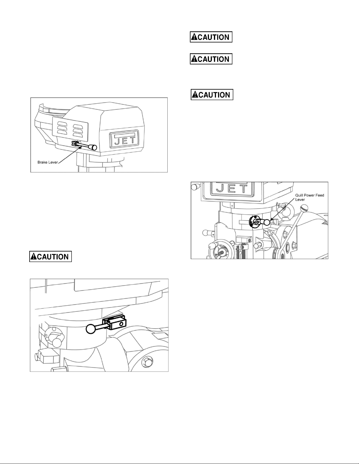
9.7 Quill power feed lever
The dial on the EVS control panel controls the main motor
speed. Motor RPM is displayed on the LED screen.
9.5 Spindle brake
The spindle brake lever is located on upper left side of
mill head (Figure 5). Pull lever downward to apply brake.
The spindle brake lever is used only after motor switch
has been set to OFF. The spindle will not stop with motor
running.
Figure 5
9.6 High-neutral-low shift lever
The mill head can be driven directly (High Speed) or
through the back gear (Low Speed) in the mill head. The
selection is made by changing the position of shift lever.
The shift lever is located at lower right side of mill head
(Figure 6). The lever position closest to operator is High
setting. The lever position away from operator is Low
setting. The middle position is Neutral setting.
Do not shift the High-Low Gear
Lever while the motor is running.
Rotate the spindle by hand to facilitate changing
lever positions.
Do not use power feed at speeds
above 3000 R.P.M.
It is recommended to disengage the
power feed worm gear whenever power feed is not
required. This avoids unnecessary wear on worm
gear.
Do not move Quill Power Feed
Lever unless motor is at a
complete stop. When changing lever position, do it
gently. If gear does not engage, jog the motor and
allow it to stop before attempting to change.
The quill power feed lever is located on right side of mill
head (Figure 9). It is used to engage and disengage the
quill power feed mechanism.
The power feed is engaged by pulling out the knob and
rotating handle to a new locked position. When engaged,
the power feed mechanism will drive spindle upward or
downward. The power feed mechanism will not drive
spindle when handle is in disengaged position.
Figure 7
9.8 Feed rate lever
Figure 6
The Feed Rate Lever (Figure 8) is used to set the perrevolution rate of the power feed mechanism. Three feed
rates are available: 0.0015-inch, 0.003-inch, and 0.006inch per revolution. The positions are shown on an
indicator plate under the feed rate lever.
The rate is selected by pulling out knob on feed rate lever
and moving handle to the detent of desired feed rate.
Note: The knob is spring loaded – pull out to rotate to
new position.
Unlike other controls on the machine, the lever shifts into
engagement more easily with the motor running, and the
quill feed lever engaged.
14

Figure 8
9.9 Feed trip cam lever
The Feed Trip Cam Lever (A, Figure 9) is located on left
side of head behind the Manual Fine Feed Handwheel
(B, Figure 9). It engages the overload clutch on the pinion
shaft when positioned to the left. The Feed Trip Cam
Lever stays engaged until Quill Stop (C, Figure 12)
comes in contact with Micrometer Adjusting Nut (A,
Figure 12) forcing it to drop out automatically, or until it is
released manually by engaging the lever to the right.
It is recommended that Feed
Direction Knob be left in neutral
position when not in use.
Figure 10
9.11 Coarse feed handle
The Coarse Feed Handle (A, Figure 11) is located on
right side of head. The Coarse Feed Handle is used for
non-precision drilling operations and for moving quill to a
specific depth. A return spring will retract spindle
automatically once handle is released.
Figure 9
9.10 Feed direction control
The Feed Direction Control (B, Figure 10) determines
whether the power feed will move up, down, or not move
at all. The position of knob depends upon direction of
spindle rotation (see the Motor Switch section). Position
of the control may be changed with the system stopped
or running. If the control does not engage easily, move
fine feed handwheel (A, Figure 10) back and forth to aid
engagement.
If spindle is rotating clockwise, in is downfeed; out is
upfeed. If spindle rotation is counterclockwise, out is
downfeed; in is upfeed. Neutral position is between in and
out position.
9.12 Quill lock handle
The Quill Lock Handle (B, Figure 11) is located on right
side of head. Rotate handle clockwise to lock quill in
desired position. Rotate handle counter-clockwise to
release.
Figure 11
9.13 Micrometer adjusting nut
The Micrometer Adjusting Nut (A, Figure 12) is located on
front of head. Use for setting specific spindle depth.
Secure with lock nut (B, Figure 12).
15
 Loading...