

Jet JPS2-115, JPS2-230, ProShop II JPS2-230, ProShop II JPS2-115 Operating Instructions And Parts Manual

Operating Instructions and Parts Manual
ProShop II™ 10-inch Table Saw
Model JPS2-115, JPS2-230
shown with cast wings, 52” rail set, and extension table
JET
427 New Sanford Road
LaVergne, Tennessee 37086 Part No. M-725000
Ph.: 800-274-6848 Edition 1 09/2017
www.jettools.com Copyright © 2017 JET

1.0 IMPORTANT SAFETY
INSTRUCTIONS
WARNING: Read all safety warnings, instructions,
illustrations and specifications provided with this
power tool. Failure to follow all instructions listed
below may result in electric shock, fire and/or
serious injury.
Save all warnings and instructions for future
reference.
1.1 General Safety Warnings
Work area safety
•
Keep work area clean and well lit.
dark areas invite accidents.
•
Do not operate power tools in explosive
atmospheres, such as in the presence of
flammable liquids, gases or dust.
create sparks which may ignite the dust or fumes.
•
Keep children and bystanders away while
operating a power tool.
you to lose control.
Distractions can cause
Electrical safety
•
Power tool plugs must match the outlet. Never
modify the plug in any way. Do not use any
adapter plugs with earthed (grounded) power
Unmodified plugs and matching outlets will
tools.
reduce risk of electric shock.
•
Avoid body contact with earthed or grounded
surfaces, such as pipes, radiators, ranges and
refrigerators.
shock if your body is earthed or grounded.
•
Do not expose power tools to rain or wet
conditions.
increase the risk of electric shock.
•
Do not abuse the cord. Never use the cord for
carrying, pulling or unplugging the power tool.
Keep cord away from heat, oil, sharp edges or
moving parts.
increase the risk of electric shock.
•
When operating a power tool outdoors, use an
extension cord suitable for outdoor use.
cord suitable for outdoor use reduces the risk of
electric shock.
•
If operating a power tool in a damp location is
unavoidable, use a GFCI (ground fault circuit
interruptor) protected supply.
reduces the risk of electric shock.
There is an increased risk of electric
Water entering a power tool will
Damaged or entangled cords
Cluttered or
Power tools
Use of a
Use of a GFCI
Personal safety
•
Stay alert, watch what you are doing and use
common sense when operating a power tool. Do
not use a power tool while y ou are tired or under
the influence of drugs, alcohol or medication.
moment of inattention while operating power tools
may result in serious personal injury.
•
Use personal protective equipment. Always
wear eye protection.
dust mask, non-skid safety shoes, hard hat, or
hearing protection used for appropriate conditions
will reduce personal injuries.
•
Prevent unintentional starting. Ensure the
switch is in the off-position before connecting to
power source and/or battery pack, picking up or
carrying the tool.
finger on the switch or energising power tools that
have the switch on invites accidents.
•
Remove any adjusting key or wrench before
turning the powe r tool on.
attached to a rotating part of the power tool may
result in personal injury.
•
Do not overreach. Keep proper footing and
balance at all times.
the power tool in unexpected situations.
•
Dress properly. Do not wear loose clothing or
jewelry. Keep your hair, clothing and gloves
away from moving parts.
long hair can be caught in moving parts.
•
If devices are provided for the connection of
dust extraction and collection facilities, ensure
these are connected and properly used.
dust collection can reduce dust-related hazards.
•
Do not let familiarity gained from frequent use of
tools allow you to become complacent and
ignore tool safety principles.
can cause severe injury within a fraction of a
second.
Protective equipment such as
Carrying power tools with your
A wrench or a key left
This enables better control of
Loose clothes, jewelry or
A careless action
Power tool use and care
•
Do not force the power tool. Use the correct
power tool for your application.
power tool will do the job better and safer at the rate
for which it was designed.
•
Do not use the power tool if the switch does not
turn it on and off.
controlled with the switch is dangerous and must be
repaired.
•
Disconnect the plug from the power source
and/or remove the battery pack, if detachable,
from the power tool before making any
adjustments, changing accessories, or storing
power tools.
reduce the risk of starting the power tool
accidentally.
Any power tool that cannot be
Such preventive safety measures
The correct
A
Use of
2

•
Store idle power tools out of the reach of
children and do not allow persons unfamiliar
with the power tool or these instructions to
operate the power tool.
dangerous in the hands of untrained users.
•
Maintain power tools and accessories. Check
for misalignment or binding of moving parts,
breakage of parts and any other condition that
may affect the power tool’s operation. If
damaged, have the power tool repaired before
Many accidents are caused by poorly
use.
maintained power tools.
•
Keep cutting tools sharp and clean.
maintained cutting tools with sharp cutting edges
are less likely to bind and are easier to control.
•
Use the power tool, accessories and tool bits
etc. in accordance with these instructions,
taking into a ccount the worki ng conditions and
the work to be pe rformed.
for operations different from those intended could
result in a hazardous situation.
•
Keep handles and grasping surfaces dry, clean
and free from oil and grease.
and grasping surfaces do not allow for safe handling
and control of the tool in unexpected situations.
Service
•
Have your power tool serviced by a qualified
repair person using only identical replacement
This will ensure that the safety of the power
parts.
tool is maintained.
Power tools are
Properly
Use of the power tool
Slippery handles
1.2 Specific Safety Warnings for
Table Saws
Guarding related warnings
•
Keep guards in place. Guards must be in
working order an d be pro pe rl y mou nt ed.
that is loose, damaged, or is not functioning
correctly must be repaired or replaced.
•
Always use saw blade guard, riving knife and
anti-kickback pawls for every through-cutting
operation.
the saw blade cuts completely through the thickness
of the workpiece, the guard and other safety
devices help reduce the risk of injury.
•
Immediately reattach the guarding system after
completing an operation (such as rabbeting,
dadoing or resawing cuts) which requires
removal of the guard, riving knife and/or antikickback pawls.
kickback pawls help to reduce the risk of injury.
•
Make sure the saw blade is not contacting the
guard, riving knife or the workpiece before the
switch is turned on.
items with the saw blade could cause a hazardous
condition.
•
Adjust the riving knife as described in this
instruction manual.
For through-cutting operations where
The guard, riving knife, and anti-
Inadvertent contact of these
Incorrect spacing, positioning
A guard
and alignment can make the riving knife ineffective
in reducing the likelihood of kickback.
•
For the riving knife and anti-kickback pawls to
work, they must be engaged in the workpiece.
The riving knife and anti-kickback pawls are
ineffective when cutting workpieces that are too
short to be engaged with the riving knife and antikickback pawls. Under these conditions a kickback
cannot be prevented by the riving knife and antikickback pawls.
•
Use the appropriate saw blade for the riving
knife.
For the riving knife to function properly, the
saw blade diameter must match the appropriate
riving knife and the body of the saw blade must be
thinner than the thickness of the riving knife and the
cutting width of the saw blade must be wider than
the thickness of the riving knife.
Cutting proced ure s wa rni n gs
•
DANGER: Never place your fingers or hands in
the vicinity or in line with the saw blade.
moment of inattention or a slip could direct your
hand towards the saw blade and result in serious
personal injury.
•
Feed the workpiece into the saw blade or cutter
only against the direction of rotation.
the workpiece in the same direction that the saw
blade is rotating above the table may result in the
workpiece, and your hand, being pulled into the saw
blade.
•
Never use the miter gauge to feed the workpiece
when ripping and do not use the rip fe nce as a
length stop when cross cutting with the miter
Guiding the workpiece with the rip fence
gauge.
and the miter gauge at the same time increases the
likelihood of saw blade binding and kickback.
•
When ripping, always apply the workpiece
feeding force between the fence and the saw
blade. Use a push stick when the distance
between the fence and the saw blade is less
than 150 mm (6 in.), and use a push block when
this distance is less than 50 mm (2 in.).
helping” devices will keep your hand at a safe
distance from the saw blade.
•
Use only the push stick provided by the
manufacturer or constructed in accordance with
the instructions.
distance of the hand from the saw blade.
•
Never use a damaged or cut push stick.
damaged push stick may break causing your hand
to slip into the saw blade.
•
Do not perform any operation “freehand”.
Always use either the rip fence or the miter
gauge to position and guide the workpiece.
“Freehand” means using your hands to support or
guide the workpiece, in lieu of a rip fence or mitre
gauge. Freehand sawing leads to misalignment,
binding and kickback.
This push stick provides sufficient
Feeding
A
“Work
A
3

•
Never reach around or over a rotating saw
Reaching for a workpiece may lead to
blade.
accidental contact with the moving saw blade.
•
Provide auxiliary workpiece support to the rear
and/or sides of the saw table for long and/or
wide workpieces to keep them level.
and/or wide workpiece has a tendency to pivot on
the table’s edge, causing loss of control, saw blade
binding and kickback.
•
Feed workpiece at an even pace. Do not bend or
twist the workpiece. If jamming occurs, turn the
tool off imme diately, unplug the tool then clear
the jam.
can cause kickback or stall the motor.
•
Do not remove pieces of cut-off material while
the saw is running.
trapped between the fence or inside the saw blade
guard and the saw blade pulling your fingers into
the saw blade. Turn the saw off and wait until the
saw blade stops before removing material.
•
Use an auxiliary fence in contact with the table
top when ripping workpieces less than 2 mm
thick.
fence and create a kickback.
Jamming the saw blade by the workpiece
The material may become
A thin workpiece may wedge under the rip
A long
Kickback causes and related warnings
Kickback is a sudden reaction of the workpiece due to a
pinched, jammed saw blade or misaligned line of cut in
the workpiece with respect to the saw blade or when a
part of the workpiece binds between the saw blade and
the rip fence or other fixed object.
Most frequently during kickback, the workpiece is lifted
from the table by the rear portion of the saw blade and is
propelled towards the operator.
Kickback is the result of saw misuse and/or incorrect
operating procedures or conditions and can be avoided
by taking proper precautions as given below.
•
Never stand directly in line with the saw blade.
Always position your body on the same side of
the saw blade as the fence.
the workpiece at high velocity towards anyone
standing in front and in line with the saw blade.
•
Never reach over or in back of the saw blade to
pull or to support the workpiece.
contact with the saw blade may occur or kickback
may drag your fingers into the saw blade.
•
Never hold and press the workpiece that is
being cut off against the rotating saw blade.
Pressing the workpiece being cut off against the
saw blade will create a binding condition and
kickback.
•
Align the fence to be parallel with the saw blade.
A misaligned fence will pinch the workpiece against
the saw blade and create kickback.
•
Use a featherboard to guide the workpiece
against the table and fence when making nonthrough cuts such as rabbeting, dadoing or
Kickback may propel
Accidental
resawing cuts
workpiece in the event of a kickback.
•
Use extra caution when making a cut into blind
areas of assembled workpieces.
saw blade may cut objects that can cause kickback.
•
Support lar ge pa nels t o minimiz e the risk of saw
blade pinching and kickback.
to sag under their own weight. Support(s) must be
placed under all portions of the panel overhanging
the table top.
•
Use extra caution when cutting a workpiece that
is twisted, knotted, warped or does not have a
straight edge to guide it with a miter gauge or
along the fence.
workpiece is unstable and causes misalignment of
the kerf with the saw blade, binding and kickback.
•
Never cut more than one workpiece, stacked
vertically or horizontally.
pick up one or more pieces and cause kickback.
•
When restarting the saw with the saw blade in
the workpiece, center the saw blade in the kerf
so that the saw teeth are not engaged in the
material.
workpiece and cause kickback when the saw is
restarted.
•
Keep saw blades clean, sharp, and with
sufficient set. Never use warped saw blades or
saw blades with cracked or broken teeth.
and properly set saw blades minimize binding,
stalling and kickback.
. A featherboard helps to control the
The protruding
Large panels tend
A warped, knotted, or twisted
The saw blade could
If the saw blade binds, it may lift up the
Sharp
Table saw operating procedure warnings
•
Turn off the ta ble sa w and dis connec t the power
cord when removing the table insert, changing
the saw blade or making adjustments to the
riving knife, anti-kickback pawls or saw blade
guard, and when the machine is left unatte nded.
Precautionary measures will avoid accidents.
•
Never leave the table saw running unattended.
Turn it off and don’t leave the tool until it comes
to a complete stop.
an uncontrolled hazard.
•
Locate the table saw in a well-lit and level area
where you can maintain good footing and
balance. It should be installed in an area that
provides enou gh room to easi ly handle the s ize
of your workpiece.
uneven slippery floors invite accidents.
•
Frequently clean and remove sawdust from
under the saw table and/or the dust collection
Accumulated sawdust is combustible and
device.
may self-ignite.
•
The table saw must be secured.
is not properly secured may move or tip over.
•
Remove tools, wood scraps, etc. from the table
before the table saw is turned on.
potential jam can be dangerous.
An unattended running saw is
Cramped, dark areas, and
A table saw that
Distraction or a
4

•
Always use saw blades with correct size and
shape (diamond versus round) of arbor holes.
Saw blades that do not match the mounting
hardware of the saw will run off-center, causing loss
of control.
•
Never use damaged or incorrect saw blade
mounting means such as flanges, saw blade
washers, bolts or nuts.
were specially designed for your saw, for safe
operation and optimum performance.
•
Never stand on the table saw, do not use it as a
stepping stool.
tool is tipped or if the cutting tool is accidentally
contacted.
•
Make sure that the saw blade is installed to
rotate in the proper direction. Do not use
grinding wheels, wire brushes, or abrasive
wheels on a table saw.
installation or use of accessories not recommended
may cause serious injury.
Serious injury could occur if the
These mounting means
Improper saw blade
Additional safety rules
•
This table saw is designed and intended for use by
properly trained and experienced personnel only. If
you are not familiar with the proper and safe
operation of a table saw, do not use until proper
training and knowledge have been obtained.
•
Do not use this table saw for other than its intended
use. If used for other purposes, JET disclaims any
real or implied warranty and holds itself harmless
from any injury that may result from that use.
•
Do not wear gloves when operating a table saw.
•
WARNING: Drilling, sawing, sanding or machining
wood products generates wood dust and other
substances known to the State of California to
cause cancer. Avoid inhaling dust generated from
wood products or use a dust mask or other
safeguards to avoid inhaling dust generated from
wood products.
•
Wood products emit chemicals known to the State
of California to cause birth defects or other
reproductive harm. (California Health and Safety
Code Section 25249.6)
•
Blade should have minimum exposure during cuts.
Adjust blade to approximately 1/8” inch above
surface of workpiece.
Familiarize yourself with the following safety notices used in this manual:
This means that if precautions are not heeded, it may result in minor injury and/or possible
machine damage.
This means that if precautions are not heeded, it may result in serious or possibly fatal injury.
5

2.0 Table of contents
Section Page
1.0 IMPORTANT SAFETY INSTRUCTIONS ............................................................................................... 2
1.1 General Safety Warnings ................................................................................................................... 2
1.2 Specific Safety Warnings for Table Saws .......................................................................................... 3
2.0 Table of contents .................................................................................................................................... 6
3.0 About this manual .................................................................................................................................. 7
4.0 Table Saw terminology........................................................................................................................... 8
5.0 Specifications ......................................................................................................................................... 9
5.1 Kit configuratio ns .............................................................................................................................. 10
6.0 Setup and assembly ............................................................................................................................. 11
6.1 Shipping contents ............................................................................................................................. 11
6.2 Tools required for assembly ............................................................................................................. 12
6.3 Unpacking and cleanup .................................................................................................................... 12
6.4 Installing legs and levelers ............................................................................................................... 12
6.5 Extension wings ................................................................................................................................ 12
6.6 Handwheels ...................................................................................................................................... 13
6.7 Motor cover ....................................................................................................................................... 13
6.8 Rails and fence ................................................................................................................................. 13
6.9 Wood extension table ....................................................................................................................... 14
6.10 Switch bracket ................................................................................................................................ 14
6.11 Dust collection ................................................................................................................................ 14
6.12 Riving knife ..................................................................................................................................... 14
6.13 Anti-kickback pawls ........................................................................................................................ 14
6.14 Blade guard .................................................................................................................................... 15
6.15 Blade installation/replacement ....................................................................................................... 15
6.16 Low profile riving knife .................................................................................................................... 15
6.17 Table insert ..................................................................................................................................... 16
6.18 Miter gauge ..................................................................................................................................... 16
6.19 Tool storage .................................................................................................................................... 16
7.0 Electrical connections .......................................................................................................................... 16
7.1 GROUNDING INSTRUCTIONS ....................................................................................................... 16
7.2 Overload reset button ....................................................................................................................... 17
7.3 Extension cords ................................................................................................................................ 17
7.4 On/off switch lock-out ....................................................................................................................... 17
8.0 Adjustments ......................................................................................................................................... 18
8.1 Blade raising/tilt mechanism ............................................................................................................. 18
8.2 Adjusting blade tilt stops ................................................................................................................... 18
8.3 Riving knife alignment ...................................................................................................................... 19
8.4 Table to blade alignment .................................................................................................................. 20
8.5
Belt adjustment/replacement
9.0 Operations ............................................................................................................................................ 21
9.1 Kickbacks ......................................................................................................................................... 21
9.2 Rip sawing ........................................................................................................................................ 22
9.3 Resawing .......................................................................................................................................... 23
9.4 Crosscutting ...................................................................................................................................... 23
9.5 Bevel and miter operations ............................................................................................................... 24
10.0 Safety devices .................................................................................................................................... 25
11.0 User-maintenance .............................................................................................................................. 26
11.1 Cleaning ......................................................................................................................................... 26
11.2 Lubrication ...................................................................................................................................... 26
11.3 Additional servicing ........................................................................................................................ 26
12.0 Optional accessories .......................................................................................................................... 26
13.0 Troubleshooting JPS2 ProShop II ...................................................................................................... 27
14.0 Replacement Parts ............................................................................................................................. 27
14.1.1 Motor and Trunnion – Exploded View ......................................................................................... 28
............................................................................................................. 20
6

14.1.2 Motor and Trunnion – Parts List .................................................................................................. 29
14.2.1 Table and Cabinet– Exploded View ............................................................................................ 32
14.2.2 Table and Cabinet– Parts List ..................................................................................................... 33
14.3.1 Stand Assembly – Exploded View............................................................................................... 34
14.3.2 Stand Assembly – Parts List ....................................................................................................... 34
14.4.1 Switch Assembly – Exploded View ............................................................................................. 35
14.4.2 Switch Assembly – Parts List ...................................................................................................... 35
14.5.1 Blade Guard Assembly – Exploded View .................................................................................... 36
14.5.2 Blade Guard Assembly – Parts List............................................................................................. 37
14.6.1 Miter Gauge Assembly – Exploded View .................................................................................... 38
14.6.2 Miter Gauge Assembly – Parts List ............................................................................................. 38
15.0 Electrical Connections for JPS2 ......................................................................................................... 39
16.0 Warranty and Service......................................................................................................................... 40
3.0 About this manual
This manual is provided by JET covering the safe operation and maintenance procedures for a JET Model
JPS2 ProShop II™ Table Saw. This manual contains instructions on installation, safety precautions, general
operating procedures, maintenance instructions and parts breakdown. Your machine has been designed and
constructed to provide consistent, long-term operation if used in accordance with the instructions as set forth in
this document.
This manual is not intended to be an exhaustive guide to table saw operational methods, use of jigs or aftermarket accessories, choice of stock, etc. Additional knowledge can be obtained from experienced users, trade
articles, or website forums. Whatever accepted methods are used, always make personal safety a priority.
If there are questions or comments, please contact your local supplier or JET. JET can also be reached at our
web site: www.jettools.com.
Retain this manual for future reference. If the machine transfers ownership, the manual should accompany it.
Read and understand th e entire contents of this manual before attempting a ssembly
or operation. Failure to comply may cause serious injury.
Register your product using the mail-in card provided, or register online:
http://www.jettools.com/us/en/service-and-support/product-registration/
7

4.0 Table Saw terminology
Arbor: Metal shaft that connects the drive
mechanism to the blade.
Bevel Edge Cut: Tilt of the saw arbor and blade
between 0° and 45° to perform an angled cutting
operation.
Blade Guard: Mechanism mounted over the saw
blade to prevent accidental contact with the cutting
edge.
Crosscut: Sawing operation in which the miter
gauge is used to cut across the grain of the
workpiece.
Dado Blade: Blade(s) used for cutting grooves and
rabbets. A stacked dado set can be used for wider
grooves.
Dado Cut: Flat bottomed groove in the face of the
workpiece made with a dado blade.
Featherboard: Device used to keep a board
against the rip fence or table, allowing the operator
to keep hands away from saw blade.
Freehand: Moving the workpiece into the blade
using only the hands, without a fixed positioning
device. (This is a dangerous, unacceptable
procedure on a table saw – always use appropriate
devices to feed the workpiece through the saw
blade during cutting operations.)
Kerf: The resulting cut or gap made by a saw
blade.
Kickback: An event in which the workpiece is lifted
up and thrown back toward an operator, caused
when a workpiece binds on the saw blade or
between the blade and rip fence (or other fixed
object). To minimize or prevent injury from
kickbacks, see the Operations section.
Miter Gauge: A component that controls the
workpiece movement while performing a crosscut
of various angles.
Non-Through Cut: A sawing operation that
requires the removal of the blade guard and
standard riving knife, resulting in a cut that does
not protrude through the top of the workpiece
(includes dado and rabbet cuts).
The blade guard and riving knife must be reinstalled after performing a non-through cut to
avoid accidental contact with the saw blade during
operation.
Parallel: Position of the rip fence equal in distance
at every point to the side face of the saw blade.
Perpendicular: 90° (right angle) intersection or
position of the vertical and horizontal planes such
as the position of the saw blade (vertical) to the
table surface (horizontal).
Push Board/Push Stick: An instrument, usually of
wood or plastic, used to safely push the workpiece
through the cutting operation by keeping the
operator’s hands at a distance.
Rabbet: A cutting operation that creates an
L-shaped channel along the edge of the board.
Rip Cut: A cut made along the grain of the
workpiece.
Riving Knife: A metal plate fixed relative to the
blade, which moves with the blade as cutting depth
is adjusted. Thus, it maintains not only the kerf
opening in the workpiece, but also the knife-to-
blade distance. A low-profile riving knife sits lower
than the top edge of the blade, for making a nonthrough cut.
Splitter (Spreader): A stationary metal plate to
which the blade guard is attached that maintains
the kerf opening in the workpiece during a cutting
operation. (JET table saws use the superior Riving
Knife system instead.)
Standard Kerf: 1/8" gap made with a standard
blade.
Straightedge: A tool used to check that a surface
is flat or parallel.
Through Sawing: A sawing operation in which the
workpiece thickness is completely sawn through.
Proper blade height usually allows 1/8" of the top
of blade to extend above the wood stock. Keep the
blade guard down, the anti-kickback pawls down,
and the riving knife in place over the blade.
8

5.0 Specifications
Table 1
Model number
Stock number – saw only
(see Table 2 below for kit configurations)
Motor and Electricals
Motor type Totally enclosed, fan cooled, induction
Horsepower 1.75 HP
Motor phase 1 PH
Motor voltage 120 V 230 V
Cycle 60Hz
Listed FLA (full load amps) 7.4 A 14.8 A
Motor speed 3450 RPM
Starting amps 36 A 18 A
Running amps (no load) 3.7 A 1.8 A
Start capacitor 200MFD 125VAC
Run capacitor
Power transfer belt
On/off switch Magnetic switch KJD17B (NVR type)
Power cord 14AWG x 3, 6 ft (183cm)
Plug provided 5-15P 6-15P
Recommended circuit size 1 15 A
Sound emission without load 2 80 dB at 30 in. (762mm) from blade
Arbor and blade
Arbor diameter 5/8 in. (15.88 mm)
Arbor speed 4000 RPM
Arbor lock included
Arbor wrench included
Blade included 10 in. (254 mm), 40 tooth
Maximum depth of cut at 90 degrees 3-1/8 in. (79 mm)
Maximum depth of cut at 45 degrees 2-1/8 in. (54 mm)
Maximum rip to right of blade 30 in. or 52 in.
Maximum rip to left of blade 13.5 in. (343 mm)
Blade height per one revolution of handwheel 5/32 in. (4 mm) at 90°; 7/64 in. (2.83 mm) at 45°
Dado maximum width 13/16 in. (20.6 mm)
Dado maximum diameter 8 in.
Blade tilt 45° left tilt
Table
Main table dimensions, L x W 20 x 27 in. (508 x 686 mm)
Table dimensions with wings, L x W 44 x 27 in. (1118 x 686 mm)
Table area in front of blade at maximum height 8.81 in. (223.83 mm)
Table height from floor, approximate 34-3/4 in. (883 mm)
Miter T-slot, W x D 3/4 x 3/8 in. (19 x 10 mm)
Edge bevel Front
Main materials
Main table Cast iron
Table insert Aluminum
Extension wings Cast iron or stamped steel
Base and legs Steel
Center trunnion Aluminum
Pulleys Steel
JPS2-115 JPS2-230
725000 725001
40μF 300VAC
9

Dust collection
Dust port outside diameter 4 in. (102 mm)
Recommended minimum extraction volume 400 CFM (0.5 CMM)
General Dimensions
Base footprint 23-1/2 x 24-1/2 in. (597 x 623 mm)
Assembled, with 30-in. rail set, L x W x H 60 x 40 x 43 in. (1524 x 1016 x 1090 mm)
Assembled, with 52-in. rail set, L x W x H 82 x 40 x 43 in. (2083 x 1016 x 1090 mm)
Shipping dimensions, saw only, L x W x H 30 x 29-3/4 x 29 in. (76 x 75.5 x 74.5 cm)
Weights
Saw only without wings – net weight 178 lbs (81 kg)
Saw only without wings – shipping weight 191.5 lbs (87 kg)
1
subject to local/national electrical codes.
2
The specified values are emission levels and are not necessarily to be seen as safe operating levels. As workplace
conditions vary, this information is intended to allow the user to make a better estimation of the hazards and risks
involved only.
L = length, W = width, H = height, D = depth
n/a = not applicable
The specifications in this manual were current at time of publication, but because of our policy of continuous
improvement, JET reserves the right to change specifications at any time and without prior notice, without incurring
obligations.
5.1 Kit configurations
Stock numbers
120V model 230V model
Proshop II saw only
Proshop II saw, 30” rip, cast wings 725000K 725002K
Proshop II saw, 30” rip, steel wings
Proshop II saw, 52” rip, cast wings, wood extension table
Proshop II saw, 52” rip, steel wings, wood extension table
Table 2
725000 725001
725004K 725006K
725001K 725003K
725005K 725007K
10

Read and understand all
assembly instructions before attempting
assembly. Failure to comply may cause serious
injury.
6.0 Setup and assembly
6.1 Shipping contents
See Figures 6-1 and 6-2.
NOTE: Some parts may have come pre-assembled
to the table saw.
1 Table saw with on/off switch (not shown)
1 Blade (preinstalled on saw)
1 Table insert (preinstalled on saw)
1 Arbor wrench (preinstalled on tool holder)
1 Miter gauge – A
1 Push stick – B
1 Handwheel, large mounting hole – C
1 Handwheel, small mounting hole – D
1 Guard assembly – E
1 Anti-kickback pawl assembly – F
1 Riving knife – G
1 Low profile riving knife – H
1 Motor cover – J
4 Legs – K
2 Extension wings – L
1 Operator’s manual (not shown)
1 Product registration card (not shown)
1 Hardware package
6.1.2 Hardware package
1 Storage hook – HP1
1 Open end wrench 11-13mm – HP2
1 Knob – HP3
1 Spacer – HP4
3 Hex wrenches, 2.5, 4, 5 mm – HP5
4 Levelers – HP6
8 Socket hd cap screws M8x20 – HP7
8 Socket hd cap screws M6x16 – HP8
1 Soc hd cap screw w/lock wshr M5x12 – HP9
2 Tapping screws M5x12 – HP10
2 Hex cap screws w/flat wshr M8x10 – HP11
4 Pan hd machine screws M6x16 – HP12
8 Flat washers M8 – HP13
12 Flat washers M6 – HP14
4 Hex nuts M8 – HP15
NOTE: Fence and rail assemblies with fasteners,
and wood extension tables and legs with fasteners,
are shipped in separate boxes.
Figure 6-1: Contents (not to scale)
11
Figure 6-2: Hardware (not to scale)

6.2 Tools required for assembly
Hex (Allen) wrenches: 4, 5, 6mm
Open end wrenches: 10, 13mm
Cross point (Phillips) screwdriver
Straight edge
Rubber mallet (or hammer with block of wood)
Level
Note: A ratchet wrench with sockets will speed
assembly time. Additional tools may be needed for
adjustments and/or assembly of fence and rails.
The main saw unit is heavy;
use an assistant or a hoist mechanism when
moving or turning it right side up.
6.3 Unpacking and cleanup
1. Remove all contents from shipping carton and
from inside of saw body. Do not discard carton
or packing material until saw is assembled and
running satisfactorily.
2. Inspect contents for shipping damage. Report
damage, if any, to your distributor.
3. Compare contents of shipping carton with the
contents list in this manual. Report shortages,
if any, to your distributor. Check machine first
to see if parts have been pre-installed.
4. Slide table saw off pallet onto cardboard or
pad to prevent scratching table surface. Keep
saw upside down.
Install both screws first, then tighten with 5mm
hex wrench. (Note: If more clearance is
needed to insert a screw, see sect. 6.6 to
temporarily mount a handwheel and tilt the
trunnion out of the way.)
2. Install four levelers with hex nuts (HP6/14).
3. Turn saw right-side up and allow the feet to
adjust to floor surface. Place a level on table,
and adjust the levelers as needed. Tighten hex
nuts up against leg with 10mm wrench to
secure setting.
6.5 Extension wings
See Figure 6-4.
Wings are available in cast iron or stamped steel.
Make sure mating surfaces are clean and free of
burrs.
Attach each extension wing to saw table using four
screws and washers (HP7/13). Do not fully tighten
yet.
Assembly Tip: If you are doing this without an
assistant, lift extension wing perpendicular to table
edge. Install a center screw and washer, and make
snug. Then pivot wing parallel to saw table to insert
remaining three screws.
Figure 6-3
6.4 Installing legs and levelers
See Figure 6-3.
1. Mount legs (K) to cabinet using two M8 screws
with washers (HP8/13) into each leg as shown.
Figure 6-4
6.5.1 Leveling extension wings
Note: The following instructions show assembly of
the cast wings. The stamped steel wings may have
a tendency to sag until rails are installed, and may
need further leveling adjustments during rail
installation.
Level extension wings to saw table using a straight
edge. A metal straight edge is ideal, though a
carefully jointed board may also be used.
Two methods are described below: one using a
rubber mallet, the other using clamps on the table
edges.
12

Method 1 (Figure 6-5):
1. Shift extension wing so it is slightly above saw
table surface.
2. Begin by tightening the screws beneath
extension wing that secure it to saw table.
Tighten these just enough to hold wing in
place but loose enough to change wing height
by tapping on it. (Tap with rubber mallet, or
hammer over a flat block of wood. Never use a
steel-faced hammer directly on the tables.)
3. Lay straight edge across saw table and
extension wing, extending it out past edge of
wing as shown in Figure 6-5.
4. Move straight edge to several places along
wing, as you continue to nudge wing level with
saw table. Also brush your fingertips over the
seam to ensure the transition feels smooth. As
each area of wing becomes flush with table,
tighten screw under that area. Continue until
all screws are fully tightened. NOTE: Make
sure front edge of wing remains flush with front
edge of saw table.
5. Repeat above steps for opposite extension
wing.
Figure 6-6: leveling extension wings, method 2
6.6 Handwheels
See Figure 6-4.
Note: The two handwheels look identical but have
different sized mounting holes.
1. On front of table saw, slide spacer (HP4,
Figure 6-4) onto shaft followed by handwheel
with large mounting hole (C). The flat side of
handwheel hole aligns with flat side on shaft.
2. Fasten in place by screwing in lock knob
(HP3).
Figure 6-5: leveling extension wings, method 1
Method 2 (Figure 6-6):
1. Follow steps 1 through 3 from Method 1.
2. Position clamps over seam, one at front, one
at back of table. Use a pad or flat block
beneath clamp jaw to prevent damage to table
surface. See Figure 6-6.
3. Tighten both clamps to align front and back
edges of tables. Make sure front edge of wing
remains flush with front edge of saw table.
4. Tighten screws incrementally, and position
straight edge at various places across seam,
especially checking at the center. Make further
adjustments as needed.
5. Fully tighten screws.
3. Slide handwheel with small mounting hole (D)
onto shaft on right side of table saw, aligning
flat side of hole with flat side on shaft.
4. Secure handwheel with lock washer and screw
(HP9), using 4mm hex wrench.
6.7 Motor cover
See Figure 6-7.
Install motor cover (J) with four pan head screws
and washers (HP12/14).
Figure 6-7
6.8 Rails and fence
To install front and rear rails and fence, consult
manual M-725005 which accompanies your fence
assembly, then proceed to sect. 6.11.
13

6.9 Wood extension table
To install the optional wood table, consult manual
M-725005, which accompanies your fence
assembly, then proceed to sect. 6.11.
6.10 Switch bracket
See Figure 6-8.
Use two screws with washers (HP-11) to secure
switch bracket to front rail.
Figure 6-8
6.11 Dust collection
Use of a dust collection system (not provided) is
strongly recommended during table saw operation.
It will help keep the shop clean, as well as prevent
potential health issues due to dust inhalation.
A dust collection system, with minimum capacity of
400 CFM (cubic feet per minute) should be
connected to the port via a 4-inch diameter hose
(not included) and secured with a hose clamp.
Note: Dryer vent hose is not acceptable for this
purpose.
An extensive line of JET dust collectors is
available; contact your dealer or visit our website
for information.
Figure 6-9
5. Slide tabs of riving knife (D) into slot between
the two blocks, all the way down onto
mounting stud.
6. Push down lever (A) to secure riving knife.
The clamping block (Figure 6-9) is adjusted at the
factory and no further adjustment of blade guard
and riving knife assembly should be necessary.
However, proper alignment is very important.
Before operating table saw, read sect. 8.3, Riving
knife alignment, to verify and follow the adjustment
procedure if necessary.
6.13 Anti-kickback pawls
See Figures 6-10 and 6-11.
1. Push and hold button (D) on opposite side of
the head to release the catch pin. Mount pawl
assembly straight down, in the location shown
in Figure 10.
2. Pivot head and push it downward (Figure 6-11)
until there is an audible click. Make sure you
hear the click to verify that pawl assembly is
secure.
6.12 Riving knife
See Figure 6-9.
1. Disconnect machine from power source.
2. Set saw blade to 90° (vertical) position and
raise it all the way (refer to sect. 8.1).
3. Remove table insert by rotating locking knob
(shown at M, Figure 6-14) and lift up insert
using finger hole.
Use care when working around
an installed blade.
4. Through the saw table opening, pull up lever
(A, Figure 6-9). The floating clamp block (B)
will move away from the fixed block (C),
leaving a gap.
14
Figure 6-10

Figure 6-11
6.14 Blade guard
See Figure 6-12.
1. Push up guard leaves (E, Figure 6-12) until
they catch and hold on the peg (F).
2. Lower blade guard assembly onto riving knife
and push it backward to seat it.
3. Tighten knob (G).
4. Pull down guard leaves (E) and allow them to
drop to the table.
5. Reverse procedure to remove guard.
IMPORTANT: Knob (G) must be tightened before
operating saw with guard in place.
6.15 Blade installation/replacement
When installing or changing
blades, always disconnect saw from power
source. Failure to comply may cause serious
injury.
1. Disconnect machine from power source.
2. Using the handwheels, raise blade arbor fully
and lock saw at zero-degrees by tightening
lock knob at center of handwheel.
See Figure 6-13:
3. Press arbor lock paddle (H) and rotate arbor
until you feel arbor lock engage. Continue
pressing arbor lock paddle.
4. Using the provided wrench, remove arbor
nut (J) and outer flange (K). If replacing blade,
remove old blade.
5. Place new blade on arbor shaft making sure
that the teeth point down toward front of saw.
Replace flange and arbor nut (K/J).
6. Tighten arbor nut (J). Do not overtighten.
Figure 6-12
Figure 6-13
6.16 Low profile riving knife
A low profile riving knife is included with your saw.
It mounts and adjusts in the same manner as the
standard riving knife. The low profile riving knife
sits just below top of blade and is used for making
non-through cuts. The blade guard is not used with
this knife, so extra precautions should be taken
during operation.
15

6.17 Table insert
See Figure 6-14.
1. Remove blade guard and riving knife.
2. Lower blade completely.
3. Place table insert into opening with notched
end towards rear of table, as shown.
4. Adjust insert flush with table by turning four
leveling setscrews (L) and using a straight
edge at different points over the insert. A
2.5mm hex key is required to adjust the
setscrews.
5. Turn lock knob (M) so that it catches insert and
holds it against table. If lock knob will not catch
properly, remove insert and adjust spring
tension by turning the nut on the knobs’ shaft.
Figure 6-14
6.18 Miter gauge
See Figure 6-15.
Calibration
If a miter angle at the -45º, 90º or +45º is not
correct, the index stops can be adjusted by turning
one of three adjustment screws (D), then tightening
the hex nut.
Note: Always make test cuts. Do not rely solely on
miter gauge indicator marks.
6.19 Tool storage
The fence assembly can be stored on the motor
cover hooks. Arbor wrench and low profile riving
knife are stored on tool holder on right side of saw.
Below tool holder is a hook for accessory storage.
Install the additional hook (HP1) to any surface of
saw stand with the tapping screws (HP10). Drill
pilot holes before inserting screws.
7.0 Electrical connections
The JPS2-115 table saw is wired for 120-volt only.
The JPS2-230 is wired for 230-volt only. The table
saw comes with a plug designed for use on a
circuit with a grounded outlet that looks like the one
pictured in either A or D, Figure 7-1.
Before connecting to power source, be sure switch
is in off position.
It is recommended that the JPS2 table saw be
connected to a dedicated 15 amp circuit with circuit
breaker or fuse. If fuses are used, they should be
time-delay fuse marked “D”.
NOTE: Local codes take precedence over
recommendations.
7.1 GROUNDING INSTRUCTIONS
Figure 6-15
Operate miter gauge by loosening lock knob (A)
and turning miter body (B) to desired angle.
The pin (C) functions as an index stop. When
pushed in, the body will stop at -45º, 90º or +45º
when turned, as one of three screws (D) located
underneath the miter body hits the pin.
You can adjust any play of the miter gauge in the
table slot by tightening set screws (E).
1. All Grounded, Cord-connected Tools:
This machine must be grounded. In the event of a
malfunction or breakdown, grounding provides a
path of least resistance for electric current to
reduce the risk of electric shock. This tool is
equipped with an electric cord having an
equipment-grounding conductor and a grounding
plug. The plug must be plugged into a matching
outlet that is properly installed and grounded in
accordance with all local codes and ordinances.
Do not modify the plug provided - if it will not fit the
outlet, have the proper outlet installed by a
qualified electrician.
Improper connection of the equipment-grounding
conductor can result in a risk of electric shock. The
conductor with insulation having an outer surface
that is green with or without yellow stripes is the
equipment-grounding conductor. If repair or
replacement of the electric cord or plug is
necessary, do not connect the equipmentgrounding conductor to a live terminal.
16

Check with a qualified
electrician or service personnel if the
grounding instructions are not completely
understood, or if in doubt as to whether the
tool is properly grounded. Failure to comply
may cause serious or fatal injury.
Use only 3-wire extension cords that have 3-prong
grounding plugs and 3-pole receptacles that accept
the tool's plug.
Repair or replace damaged or worn cord
immediately.
2. Grounded, cord-connected tools intended for
use on a supply circuit having a nominal rating less
than 150 volts:
This tool is intended for use on a circuit that has an
outlet that looks like the one illustrated in A, Figure
7-1. An adapter, shown in B and C, may be used to
connect this plug to a 2-pole receptacle as shown
in B if a properly grounded outlet is not available.
The temporary adapter should be used only until a
properly grounded outlet can be installed by a
qualified electrician. The green-colored rigid ear,
lug, and the like, extending from the adapter must
be connected to a permanent ground such as a
properly grounded outlet box.
In Canada, the use of a temporary adaptor is not
permitted by the Canadian Electrical Code, C22.1.
3. Grounded, cord-connected tools intended for
use on a supply circuit having a nominal rating
between 150 - 250 volts, inclusive:
7.2 Overload reset button
If saw becomes overloaded and the motor shuts
off, push re-set button above switch (Figure 7-2) to
restart. If overloading happens frequently, consult
the Troubleshooting section in this manual.
Figure 7-2
7.3 Extension cords
The use of extension cords is discouraged. Try to
position machines within reach of the power
source. If an extension cord must be used, make
sure it is heavy enough to carry the current your
product will draw. An undersized cord will cause a
drop in line voltage resulting in loss of power and
overheating. Table 3 shows correct size to use
depending on cord length and nameplate ampere
rating. If in doubt, use the next heavier gauge. The
smaller the gauge number, the heavier the cord.
This tool is intended for use on a circuit that has an
outlet that looks like the one illustrated in D, Figure
7-1. The tool has a grounding plug that looks like
the plug illustrated in D. Make sure the tool is
connected to an outlet having the same
configuration as the plug. No adapter is available
or should be used with this tool. If the tool must be
reconnected for use on a different type of electric
circuit, the reconnection should be made by
qualified service personnel; and after reconnection,
the tool should comply with all local codes and
ordinances.
Figure 7-1
Ampere
Rating
More
Than
00 06 18 16 16 14
06 10 18 16 14 12
10 12 16 16 14 12
12 16 14 12
Not
More
Than
Volts Total length of cord in feet
120
240
AWG
25
50
50
100
100
200
Not
Recommended
150
300
Extension Cord Recommendations
Table 3
7.4 On/off switch lock-out
The Table Saw is equipped with a push-button
switch that will accept a safety padlock, as shown
in Figure 7-3. To safeguard your machine from
unauthorized operation and accidental starting by
young children, the use of a padlock (not included)
is highly recommended. Place the key in a location
that is inaccessible to children and others not
qualified to use the tool.
17

Figure 7-3
8.0 Adjustments
8.1 Blade raising/tilt mechanism
Never try to force the tilting
mechanism past the 45º or 90º stops. This may
cause blade misalignment.
See Figure 8-1.
To raise or lower blade, loosen lock knob (A) and
turn handwheel (B) on front of saw until desired
height is reached. Tighten lock knob. The blade
should be adjusted about 1/8" above the top
surface of the material being cut.
To tilt blade, turn lock handle (C) counterclockwise
to loosen, turn handwheel (D) until desired angle is
obtained, then tighten lock handle (C) clockwise.
Figure 8-1
8.2 Adjusting blade tilt stops
The 45° and 90° blade tilt stops have been set by
the manufacturer, but should be verified by the
operator.
1. Disconnect machine from power source.
2. Raise blade to maximum height.
Figure 8-2
If adjustment is required:
5. Remove motor cover on left side.
6. Back out the setscrew in the 90° stop collar (E,
Figure 8-3), and position collar to allow further
movement of shaft bracket.
7. Turn blade tilting handwheel until blade is
exactly 90º.
8. Turn stop collar until it contacts shaft bracket,
and tighten set screw (E).
Figure 8-3
9. Tilt blade to 45° and verify setting in the same
manner as above. See Figure 8-4. Adjust 45°
stop collar as needed (F, Figure 8-3).
3. Set blade 90º to table by turning blade tilting
handwheel (D, Figure 8-1) counterclockwise
as far as it will go. Do not force beyond stop.
4. Place a square on the table and verify that
blade is at 90º to table. See Figure 8-2. Make
sure square is flat against blade surface and
not touching a blade tooth.
Figure 8-4
Verify that blade tilt pointer (Figure 8-5) accurately
indicates 45º or 90º (0°) on scale. If not, loosen
screw and adjust pointer. Retighten screw.
18

Figure 8-5
8.3 Riving knife alignment
8.3.1 Lateral alignment
Saw blade and riving knife must be as closely
aligned as possible (lateral alignment) for
prevention of kickback. This should be checked
upon initial blade guard and riving knife installation.
Alignment should also be reaffirmed after each
blade change.
1. Disconnect machine from power source.
2. Remove blade guard and anti-kickback pawls.
3. Place a straight edge on table so it rests
against blade and riving knife. See Figure 8-6.
Rotate blade so that top of blade tooth touches
straight edge.
Figure 8-6
The saw blade and riving knife must be in line. If
adjustment is needed:
4. Pull up lever (A, Figure 8-7) and remove riving
knife, making note as to which direction riving
knife needs to be moved to align it with saw
blade.
5. Use 3mm hex key to make adjustments to four
set screws (B, Figure 8-7). Adjust any of the
set screws required to bring riving knife in
alignment with saw blade.
6. Reinsert riving knife, secure by tightening lever
(A) and check alignment per step 2.
7. Repeat steps 3–5 until alignment is correct.
Figure 8-7
8.3.2 Blade proximity alignment
The gap between saw blade and riving knife must
be between 3mm (0.12in.) and 8mm (0.32in.). See
Figure 8-8.
If adjustment is needed, note whether blade-toknife gap needs to be increased or decreased.
Then adjust as follows:
1. Disconnect machine from power source.
2. Remove blade guard, pawl assembly, table
insert and riving knife.
3. Use 3mm hex key to loosen two socket head
button screws (C, Figure 8-7). This will allow
the clamp plate (D) to slide back and forth on
the fixed base.
Slide clamp plate (D) toward or away from saw
blade as required. Attempt to make the gaps
as even as possible.
4. Tighten screws (C).
5. Reinsert riving knife; engage lever (A) and
check that saw blade/knife gap is between 3 to
8mm (Figure 8-8).
Figure 8-8
19

8.4 Table to blade alignment
Refer to Figures 8-9 and 8-10.
The table has been set square with the blade by
the manufacturer and no adjustment is necessary
now. As the saw receives extensive use, however,
table/blade squareness should be checked and
corrected if necessary. Use the miter slot to do this:
1. Disconnect machine from power source.
2. Raise blade to maximum height.
3. Mark one tooth (A) with a grease pencil and
position the tooth slightly above top edge of
table at the front.
8. Retighten mounting screws firmly.
9. Verify the alignment, angle pointer setting,
fence setting, etc. Make any further
adjustments as needed.
8.5
Belt adjustment/replacement
To adjust tension of drive belt:
1. Disconnect machine from power source.
2. Loosen bolt (C, Figure 8-11) in motor bracket
slot. If needed, also slightly loosen hex nut on
opposite side of motor bracket.
3. Shift motor as needed, downward to tighten
belt, upward to loosen.
4. Retighten bolt (and hex nut).
To replace belt, loosen bolt (C) and shift motor
upward to create sufficient slack in belt. Remove
old belt from pulleys and install new one. Tension
new belt and retighten bolt.
Figure 8-9
4. Raise the miter gauge slightly out of its slot to
serve as a shoulder. Place a sliding square (B)
against side of miter bar, slide the scale over
until it touches the tip of blade, and lock the
scale in position. See Figure 8-9.
5. Rotate marked tooth (A) so that it is slightly
above table top at the rear and, using the
square as before, verify that the distance to
the blade is the same. See Figure 8-10. If the
distances are not the same, make a careful
note of the difference.
Figure 8-10
6. Slightly loosen the three mounting screws
(#10, sect. 14.2.1) that hold the table to the
stand; two in front, one in back.
7. Nudge table to bring miter slot in line with
blade.
Figure 8-11
20

9.0 Operations
NOTE: The following Figures are general in nature
and may not show your particular saw model.
Familiarize yourself with the location and operation
of all controls and adjustments and the use of
accessories such as miter gauge and rip fence.
9.1 Kickbacks
Serious injury can result from kickbacks which
occur when a workpiece binds on the saw blade or
binds between the blade and rip fence or other
fixed object. This binding can cause work piece to
lift up and be thrown toward the operator.
Listed below are conditions which can cause
kickbacks:
• Confining the cutoff piece when crosscutting or
ripping.
• Releasing the workpiece before completing
operation or not pushing work piece all the
way past the saw blade.
• Not using the splitter/riving knife when ripping
or not maintaining alignment of the
splitter/riving knife with the saw blade.
• Using a dull saw blade.
• Not maintaining alignment of the rip fence so
that it tends to angle toward rather than away
from the saw blade front to back.
• Applying feed force when ripping to the cutoff
(free) section of the workpiece instead of the
section between saw blade and fence.
Figure 9-1
Dull, badly set, improper, or improperly filed cutting
tools and cutting tools with gum or resin adhering
to them can cause accidents. Never use a cracked
saw blade. The use of a sharp, well maintained,
and correct cutting tool for the operation will help
avoid injuries.
Support the work properly and hold it firmly against
gauge or fence. Use a push stick or push block
when ripping short, narrow (6" width or less), or
thin work. Use a push block or miter gauge holddown when dadoing or molding.
For increased safety in crosscutting, use an
auxiliary wood facing (Figure 9-2) attached to the
miter gauge, using the slots or holes provided in
the gauge.
• Ripping wood that is twisted (not flat), or does
not have a straight edge, or a twisted grain.
To minimize or prevent injury from kickbacks:
• Avoid conditions listed above.
• Wear a safety face shield, goggles, or glasses.
• Do not use the miter gauge and rip fence in
the same operation unless provision is made
by use of a facing board on the fence so as to
allow the cutoff section of the workpiece to
come free before the next cut is started (See
Figure 9-9).
• As the machine receives use, the operation of
the anti-kickback pawls should be checked
periodically (Figure 9-1). If the pawls do not
stop the reverse motion of a workpiece,
resharpen all the points.
• Where possible, keep your face and body out
of line with potential kickbacks including when
starting or stopping the machine.
Figure 9-2
Never use the fence as a length stop when
crosscutting. Do not hold or touch the free end or
cutoff section of a workpiece. On through-sawing
operations, the cutoff section must NOT be
confined.
Always keep your hands out of line of the saw
blade and never reach back of the cutting blade
with either hand to hold the workpiece.
Bevel ripping cuts should always be made with the
fence on the right side of saw blade so that the
blade tilts away from the fence and minimizes the
possibility of the work binding and the resulting
kickback.
21

9.2 Rip sawing
Ripping is where the workpiece is fed with the grain
into the saw blade using the fence as a guide and
a positioning device to ensure the desired width of
cut (Figure 9-3).
Figure 9-3
Before starting a ripping cut,
verify that fence is clamped securely and
aligned properly.
• Never rip freehand or use miter gauge in
combination with the fence.
• Never rip workpieces shorter than the saw
blade diameter.
Figure 9-4
In ripping, use one hand to hold the board down
against the fence or fixture, and the other to push it
into the blade between blade and fence. If
workpiece is narrower than 6" or shorter than 12",
use a push stick or push block to push it through
between fence and blade (Figure 9-5). Never push
in a location such that the pushing hand is in line
with the blade. Move the hand serving as a holddown a safe distance from blade as cut nears
completion. For very narrow ripping where a push
stick cannot be used, use a push block or auxiliary
fence. Always push the workpiece completely past
the blade at the end of a cut to minimize the
possibility of a kickback.
• Never reach behind the blade with either hand
to hold down or remove the cutoff piece with
the saw blade rotating.
Always use blade guard, splitter/riving knife and
anti-kickback pawls. Make sure splitter/riving knife
is properly aligned. When wood is cut along the
grain, the kerf tends to close and bind on the blade
and kickbacks can occur.
The rip fence (A, Figure 9-4) should be set for the
width of the cut (C) by using the scale on the front
rail, or by measuring the distance between blade
(B) and fence (A). Stand out of line with saw blade
and workpiece to avoid sawdust and splinters
coming off the blade or a kickback, if one should
occur.
If the work piece does not have a straight edge,
nail an auxiliary straight edged board on it to
provide one against the fence. To cut properly, the
board must make good contact with the table. If it
is warped, turn the hollow side down. Do not
attempt to cut boards with significant warp.
Figure 9-5
22

Figure 9-6
When ripping long boards, use a support at front of
table (A, Figure 9-6), such as a roller stand, and a
support or "tailman" (B) at the rear.
Never use the rip fence beyond the point where the
carriage is flush with the end of the rails.
Have the blade extend about 1/8" above the top of
the workpiece. Exposing the blade above this point
can be hazardous.
9.3 Resawing
Resawing is a ripping operation in which thick
boards are cut into thinner ones. Narrow boards up
to 3" can be resawn in one pass. Wider boards up
to 6" must be resawn in two passes.
In resawing wider boards, adjust the blade height
so as to overlap the two cuts by 1/2" as shown in
Figure 9-7. Too deep a first cut can result in
binding and possible kickbacks on the second cut.
Always use the same side of the board against the
fence for both cuts.
Figure 9-8
Crosscutting should never be done freehand nor
should the fence be used as an end stop unless an
auxiliary block (A, Figure 9-9) is clamped to the
front of the blade area such that the cutoff piece
comes free of the block before cutting starts.
Figure 9-9
Length stops should not be used on the free end of
the workpiece in the cutoff area.
Do not crosscut workpieces shorter than 6". Before
starting a cut, be sure the miter gauge is securely
clamped at the desired angle. Hold the workpiece
firmly against the table and back against the miter
gauge. Always use the saw guard and riving knife
and make sure the riving knife is properly aligned.
Figure 9-7
9.4 Crosscutting
Crosscutting is where the workpiece is fed cross
grain into the saw blade using the miter gauge to
support and position the workpiece (Figure 9-8).
For 90-degree crosscutting, most operators prefer
to use the left-hand miter gauge slot. When using it
in this position, hold the workpiece against the
gauge with the left hand and use the right hand to
advance the workpiece. When using the right hand
slot for miter and compound crosscutting so that
the blade tilts away from the gauge, the hand
positions are reversed.
When using the miter gauge, the workpiece must
be held firmly and advanced smoothly at a slow
rate. If the workpiece is not held firmly, it can
vibrate causing it to bind on the blade and dull the
saw teeth.
23

To improve the effectiveness of the miter gauge in
crosscutting, some users mount an auxiliary
wooden extension face (A, Figure 9-10) with a
glued-on strip of sandpaper (B) to the miter gauge.
Provide auxiliary support for any workpiece
extending beyond the table top with a tendency to
sag and lift up off the table.
Have the blade extend about 1/8" above the top of
the workpiece. Exposing the blade above this point
can be hazardous.
Figure 9-10
Note: When making compound miters (with blade
tilted) use the miter gauge in the right hand slot to
provide more hand clearance and safety.
Have the blade extend only 1/8" above the top of
the workpiece. Exposing the blade above this point
can be hazardous.
Figure 9-12
Dado cutting – Dadoing is cutting a wide groove
into a workpiece or cutting a rabbet along the edge
of a workpiece. A dado insert (optional accessory,
not provided) shown in Figure 9-13, is necessary
for this type of operation.
9.5 Bevel and miter operations
Bevel cut – A bevel cut is a special type of
operation where the saw blade is tilted at an angle
less than 90 degrees to the table top (Figure 9-11).
Operations are performed in the same manner as
ripping or crosscutting, except the fence or miter
gauge should be used on the right-hand side of the
blade to provide added safety in avoiding a binding
action between blade and table top. When beveling
with the miter gauge, the workpiece must be held
firmly to prevent creeping.
Figure 9-11
Mitering – Crosscuts made at an angle to the edge
of the workpiece are called miters (Figure 9-12).
Set the miter gauge at the required angle, lock the
miter gauge, and make the cut the same as a
normal crosscut except the workpiece must be held
extra firmly to prevent creeping.
Do not use the standard table
insert for dadoing operations.
Figure 9-13
The process of cutting 1/8" to 13/16" grooves in
workpieces is accomplished by the use of a
stacked dado blade set or an adjustable type blade
mounted on the saw arbor. By using various
combinations of stacked dado blades, or properly
setting the dial on an adjustable blade, an accurate
width dado can be made. This is very useful for
shelving, making joints, tenoning, etc. The guard,
riving knife, and anti-kickback pawls supplied with
the saw should be used for all cutting operations
where they can be used. When performing
operations where the guard cannot be used, as in
some dadoing operations, alternative safety
precautions should be taken.
These include push sticks, feather boards, filler
pieces, fixtures, jigs and any other appropriate
device that can be utilized to keep operators’
hands away from the blade. Upon completion of
the operation requiring removal of the guard, the
entire guard assembly must be placed back on the
machine in its proper working order.
24

Never use a dado head in a
tilted position. Never operate the saw without
the blade guard, riving knife and anti-kickback
pawls for operations where they can be used.
10.0 Safety devices
Feather board
The feather board (Figure 10-1) should be made of
straight grain hardwood approximately 1" thick and
4" to 8" wide depending on the size of the machine.
The length is developed in accordance with
intended use. Feather boards can be fastened to
the table or rip fence by use of C-clamps.
Alternatively, drilled and tapped holes in the table
top allow the use of wing nuts and washers as a
method of clamping. If this method of fastening is
used, provide slots in the feather board for
adjustment. (The illustration shows a method of
attaching and use of the feather board as a vertical
comb. The horizontal application is essentially the
same except that the attachment is to the table
top.)
Figure 10-2 – Push Block Template
Figure 10-1
Push stick & push block
The use of a push block or push stick provides an
added level of safety for the operator. A push stick
is included with your table saw, but you may wish
to make others personalized for different cutting
procedures. The templates in Figures 10-2 and 103 offer construction details.
Figure 10-3 – Push stick template
25
11.0 User-maintenance
12.0 Optional accessories
Always disconnect power to
the machine before performing maintenance.
Failure to do this may result in serious
personal injury.
11.1 Cleaning
Clean the JPS2 according to the schedule below to
ensure maximum performance. The schedule
assumes the saw is being used every day.
Daily:
• Use a brush or compressed air to remove
chips or debris – do not use bare hands.
• Wipe down the table surface and T-slots
with a rust preventive.
• Clean pitch and resin from the saw blade.
Weekly:
• Clean motor housing with compressed air.
• Wipe down fence rails with a dry silicon
lubricant.
These accessory items, purchased separately, can
enhance the functionality of your table saw.
Contact your dealer to order, or call JET at the
phone number on the cover.
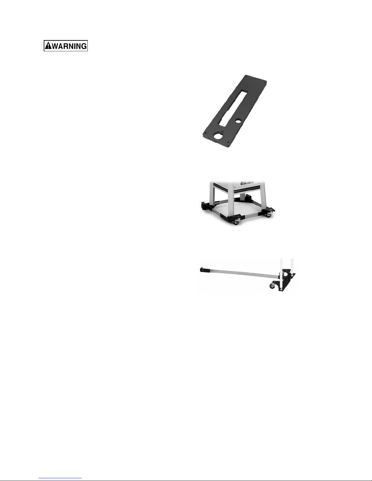
# 725004 – Dado Insert for ProShop II
11.2 Lubrication
Lubricate the areas indicated below every 12
months.
• Lubricate blade angling trunnions with 6 or 7
drops of light machine oil.
• Lubricate the blade height trunnion with 6 or
7 drops of light machine oil.
• Worm gears and threads should be
lubricated with an automotive wheel bearing
grease.
• Check all adjustments after lubricating.
11.3 Additional servicing
Any additional servicing should be performed by
authorized service personnel.
# 708119 – Universal Mobile Base, adjustable up
to 36” x 36”
# 708158 – Mobile Base Extension Kit (for saws
equipped with wood extension table)
26

13.0 Troubleshooting JPS2 ProShop II
Symptom Possible Cause Correction
Motor will not start Low voltage. Check power line for proper voltage.
Open circuit in motor or loose
connection.
Motor will not start: fuses
or circuit breakers blow.
Motor overheats. Motor overloaded. Reduce load on motor.
Motor stalls, resulting in
blown fuses or tripped
circuit.
Machine slows when
operating.
Loud, repetitive noise
coming from machine.
Short circuit in line cord or plug. Inspect cord or plug for damaged insulation
Short circuit in motor or loose
connections.
Incorrect fuses or circuit breakers in
power line.
Air circulation through the motor
restricted.
Motor overloaded. Reduce load on motor.
Short circuit in motor or loose
connections.
Low voltage. Correct the low voltage conditions.
Incorrect fuses or circuit breakers in
power line.
Applying too much pressure to
workpiece.
Belt loose. Tighten belt.
Pulley setscrews or keys are missing
or loose.
Motor fan is hitting the cover. Tighten fan or shim cover.
Inspect all lead connections on motor for
loose or open connections.
and shorted wires.
Inspect all connections on motor for loose or
shorted terminals or worn insulation.
Install correct fuses or circuit breakers.
Clean motor fan with compressed air to
restore normal air circulation.
Inspect connections on motor for loose or
shorted terminals or worn insulation.
Install correct fuses or circuit breakers.
Feed workpiece more slowly.
Inspect keys and setscrews. Replace or
tighten if necessary.
Drive belt is defective. Replace belt.
Blade not square with
miter slot, or fence not
square to blade.
Blade does not reach 90
degrees.
Blade is warped. Replace saw blade.
Table top not parallel to blade. Adjust table parallel to blade.
Fence not parallel to blade. Adjust fence parallel to blade.
90 degree stop is out of adjustment. Adjust 90 degree stop.
Table 4
14.0 Replacement Parts
Replacement parts are listed on the following pages. To order parts or reach our service department, call 1800-274-6848 Monday through Friday (see our website for business hours, www.jettools.com). Having the
Model Number and Serial Number of your machine available when you call will allow us to serve you quickly
and accurately.
Non-proprietary parts, such as fasteners, can be found at local hardware stores, or may be ordered from JET.
Some parts are shown for reference only, and may not be available individually.
27
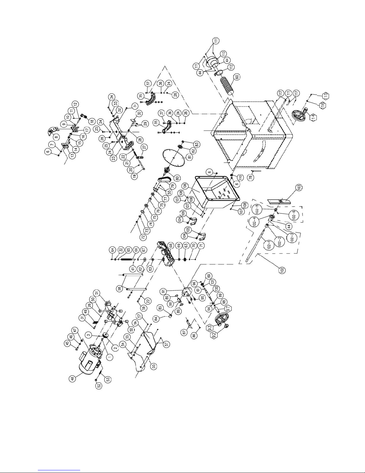
14.1.1 Motor and Trunnion – Exploded View
28

14.1.2 Motor and Trunnion – Parts List
Index No Part No Description Size Qty
1 ................ 6291479 .................... Key, Dbl Rd Hd ........................................................ 5x5x30mm .................... 1
2 ................ JPS10TSC-102 ......... Motor Pulley ............................................................. ...................................... 1
3 ................ TS-2276081 .............. Socket Set Screw .................................................... M6-1.0Px8 .................... 2
6 ................ TS-1541031 .............. Nylon Lock Hex Nut ................................................. M8-1.25P ...................... 3
7 ................ F006042 .................... C-Retaining Ring, Ext .............................................. STW-14 ......................... 1
8 ................ JPS10TSC-108 ......... Low Profile Riving Knife ........................................... ...................................... 1
9 ................ TS-2276081 .............. Socket Set Screw .................................................... M6-1.0Px8 .................... 4
10 .............. TS-1533052 .............. Phillips Pan Hd Machine Screw ............................... M5-0.8Px16 .................. 2
11 .............. JPS10TSC-111 ......... Pin............................................................................ ...................................... 1
12 .............. JPS10TSC-112 ......... Bolt........................................................................... ...................................... 1
13 .............. JPS10TSC-113 ......... Riving Knife Clamp Base ......................................... ...................................... 1
14 .............. TS-1504031 .............. Socket Head Cap Screw ......................................... M8-1.25Px16 ................ 2
15 .............. JPS10TSC-115 ......... Spring ...................................................................... ...................................... 1
16 .............. JPS10TSC-116 ......... Bushing .................................................................... ...................................... 1
17 .............. JPS10TSC-117 ......... Riving Knife Clamp Plate ......................................... ...................................... 1
18 .............. JPS10TSC-118 ......... Lock Handle ............................................................. ...................................... 1
19 .............. JPS10TSR-139 ......... Bolt........................................................................... ...................................... 1
20 .............. JWTS10-138 ............. E-Retaining Ring ..................................................... ETW-8 ........................... 1
21 .............. JWTS10-141 ............. Spring ...................................................................... ...................................... 1
22 .............. TS-1550061 .............. Flat Washer ............................................................. M8 ................................. 3
23 .............. JPS10TSC-123 ......... Trunnion Base ......................................................... ...................................... 1
24 .............. TS-2361081 .............. Lock Washer ............................................................ M8 ................................. 9
25 .............. TS-1504041 .............. Socket Head Cap Screw ......................................... M8-1.25Px20 ................ 2
26 .............. TS-1540061 .............. Hex Nut .................................................................... M8-1.25P ...................... 6
27 .............. JWTS10-140 ............. Lock Handle Kit ....................................................... ...................................... 1
28 .............. JPS10TSC-128 ......... Spring ...................................................................... ...................................... 1
29 .............. F006080 .................... E-Retaining Ring ..................................................... ETW-9 ........................... 2
30 .............. JPS10TSC-130 ......... Spindle Lock Paddle ................................................ ...................................... 1
31 .............. TS-1504041 .............. Socket Head Cap Screw ......................................... M8-1.25Px20 ................ 2
32 .............. TS-1550041 .............. Flat Washer ............................................................. M6 ................................. 2
33 .............. JWTS10-125. ............ Spring ...................................................................... ...................................... 1
34 .............. TS-1482081 .............. Hex Cap Screw ........................................................ M6-1.0Px40 .................. 1
35 .............. JPS10TSR-173 ......... Front & Rear Trunnion ............................................. ...................................... 2
36 .............. TS-1550061 .............. Flat Washer ............................................................. M8 ................................. 7
37 .............. TS-1490041 .............. Hex Cap Screw ........................................................ M8-1.25Px25 ................ 4
44 .............. TS-1541011 .............. Nylon Lock Hex Nut ................................................. M5 ................................. 5
45 .............. TS-1491041 .............. Hex Cap Screw ........................................................ M10-1.5Px30 ................ 1
46 .............. TS-2361101 .............. Lock Washer ............................................................ M10 ............................... 1
47 .............. TS-1550071 .............. Flat Washer ............................................................. M10 ............................... 1
48……….JPS10TSC-148-120 ..... Motor........................................................................ 1.75HP 1PH 120V ........ 1
………….JPS10TSC-148-230 ...... Motor........................................................................ 1.75HP 1PH 230V ........ 1
...............JPS10TSC-148MF ........ Motor Fan (not shown)............................................. ...................................... 1
...............JPS10TSC-148MFC ..... Motor Fan Cover (not shown) .................................. ...................................... 1
...............JPS10TSC-148CS ........ Centrifugal Switch (not shown) ................................ ..................................... 1
...............JPS10TSC-148SCC ...... Starting Capacitor Cover (not shown)...................... ...................................... 1
...............JPS10TSC-148RCC ..... Running Capacitor Cover (not shown)..................... ...................................... 1
...............JPS10TSC-148SC ........ Starting Capacitor (not shown) ................................ 200MFD, 125VAC ......... 1
...............JPS10TSC-148RC ........ Running Capacitor (not shown) ............................... 40
...............JPS10TSC-148JB ......... Junction Box (not shown) ........................................ ..................................... 1
...............JPS10TSC-148JBC ...... Junction Box Cover (not shown) .............................. ...................................... 1
49 .............. JPS10TSC-149 ......... Spring ...................................................................... ...................................... 1
50 .............. JPS10TSC-150 ......... Bushing .................................................................... ...................................... 4
51 .............. JPS10TSC-151 ......... Level Bracket ........................................................... ...................................... 1
52 .............. TS-2342101 .............. Nylon Lock Hex Nut ................................................. M10-1.5P ...................... 1
53 .............. JPS10TSC-153 ......... Motor Bracket Pivot ................................................. ...................................... 1
54 .............. JPS10TSC-154 ......... Cover ....................................................................... ...................................... 1
55 .............. TS-1533042 .............. Phillips Pan Hd Machine Screw ............................... M5-0.8Px12 .................. 6
56 .............. JPS10TSC-156 ......... Lower Dust Chute .................................................... ...................................... 1
57 .............. TS-1533032 .............. Phillips Pan Hd Machine Screw ............................... M5-0.8Px8 .................... 5
58 .............. JPS10TSC-158 ......... Guide Bar................................................................. ...................................... 2
μF, 300VAC .............. 1
29

Index No Part No Description Size Qty
59 .............. TS-1504071 .............. Socket Head Cap Screw ......................................... M8-1.25Px35 ................ 2
60 .............. JPS10TSC-160 ......... Hose ........................................................................ 2.5 ................................. 1
61 .............. JWP12-118 ............... Key, Dbl Rd Hd ........................................................ 4x4x8mm ...................... 2
62 .............. JPS10TSC-162 ......... Plate......................................................................... ...................................... 1
63 .............. BB-51100 .................. Thrust Bearing ......................................................... 51100 ............................ 2
64 .............. TS-1482031 .............. Hex Cap Screw ........................................................ M6-1.0Px16 .................. 1
65 .............. TS-1550041 .............. Flat Washer ............................................................. M6 ................................. 1
66 .............. JPS10TSC-166 ......... Lead Screw .............................................................. ...................................... 1
67 .............. F006044 .................... C-Retaining Ring, Ext .............................................. STW-16 ......................... 1
68 .............. JPS10TSC-168 ......... Lower Bracket .......................................................... ...................................... 1
69 .............. JPS10TSC-169 ......... Bevel Gear ............................................................... ...................................... 2
70 .............. TS-1550041 .............. Flat Washer ............................................................. M6 ................................. 1
71 .............. TS-1541021 .............. Nylon Lock Hex Nut ................................................. M6-1.0P ........................ 1
72 .............. TS-2342101 .............. Nylon Lock Hex Nut ................................................. M10-1.5P ...................... 1
73 .............. TS-1550071 .............. Flat Washer ............................................................. M10 ............................... 1
74 .............. F006033 .................... C-Retaining Ring, Int ............................................... RTW-35 ........................ 1
75 .............. BB-6003ZZ ................ Ball Bearing ............................................................. 6003ZZ ......................... 2
76 .............. JPS10TSC-176 ......... Spacer ..................................................................... ...................................... 1
77 .............. JPS10TSC-177 ......... Bearing Cover .......................................................... ...................................... 1
78 .............. JPS10TSC-178 ......... Cable Clamp ............................................................ ...................................... 1
79 .............. JPS10TSC-179 ......... Belt........................................................................... 142-J7 ........................... 1
80 .............. JPS10TSC-180 ......... Arbor ........................................................................ 5/8” ................................ 1
81 .............. JPS10TSR-131 ......... Saw Blade ............................................................... 10"x40T ......................... 1
82 .............. JPS10TSC-182 ......... Arbor Flange ............................................................ ...................................... 1
83 .............. JWTS10-133 ............. Arbor Nut ................................................................. 5/8"-12 .......................... 1
84 .............. TS-1523011 .............. Socket Set Screw .................................................... M6-1.0Px6 .................... 1
85 .............. JPS10TSC-185 ......... Limit Nut................................................................... ...................................... 1
86 .............. TS-1533042 .............. Phillips Pan Hd Machine Screw ............................... M5-0.8Px12 .................. 1
87 .............. JPS10TSC-187 ......... Indicator ................................................................... ...................................... 1
89 .............. F006050 .................... C-Retaining, Ext....................................................... STW-25 ......................... 2
90 .............. JPS10TSC-190 ......... Guide Shaft .............................................................. ...................................... 1
91 .............. JPS10TSC-191 ......... Shaft Bracket ........................................................... ...................................... 1
92............. JPS10TSC-192 .......... Knob ........................................................................ ..................................... 1
93 .............. JPS10TS-FHA ........... Front Handwheel Assembly (#93-1 thru #93-4) ....... ...................................... 1
93-1 ........... JWTS10-147 ............. Shaft (not shown) .................................................... ...................................... 1
93-2 ........... JW TS10-145 ............. Handle Cap (not shown) .......................................... ...................................... 1
93-3 ........... JPS10TS-148 ............ Handwheel (not shown) ........................................... ...................................... 1
93-4 ........... JWTS10-146 ............. Handle (not shown) ................................................. ...................................... 1
94 .............. TS-1522011 .............. Socket Set Screw .................................................... M5-0.8Px5 .................... 2
95 .............. TS-1504041 .............. Socket Head Cap Screw ......................................... M8-1.25Px20 ................ 3
96 .............. F006040 .................... C-Retaining Ring, Ext .............................................. STW-10 ......................... 1
97 .............. JPS10TSC-197 ......... Bushing .................................................................... ...................................... 1
98 .............. JPS10TSC-198 ......... O-Ring ..................................................................... P11 ............................... 1
99 .............. JPS10TSC-199 ......... Bushing .................................................................... ...................................... 1
100 ............ JPS10TSC-1100 ....... Lead Screw .............................................................. ...................................... 1
101 ............ TS-1550071 .............. Flat Washer ............................................................. M10 ............................... 1
102 ............ JPS10TSC-1102 ....... Tilting Lead Screw Assembly (#102-1 thru 102-6)... ...................................... 1
102-1 ......... JPS10TSC-11021 ..... Lead Screw .............................................................. ...................................... 1
102-2 ......... JPS10TSC-185 ......... Limit Nut................................................................... ...................................... 1
102-3 ......... TS-1523011 .............. Socket Set Screw .................................................... M6-1.0Px6 .................... 1
102-4 ......... JWTS10-159 ............. Collar Plate .............................................................. ...................................... 1
102-5 ......... JPS10TS-182 ............ Turning Ball.............................................................. ...................................... 1
102-6 ......... F012072 .................... Roll Pin .................................................................... 4x20mm ........................ 1
103 ............ JPS10TSR-160 ......... Support Bracket ....................................................... ...................................... 1
104 ............ TS-2228161 .............. Hex Cap Screw ........................................................ M8-1.25Px16 ................ 5
105 ............ JPS10TSC-1105 ....... Hook for Rip Fence .................................................. ...................................... 2
106 ............ JPS10TSC-1106 ....... Motor Cover ............................................................. ...................................... 1
107 ............ TS-1534052 .............. Phillips Pan Head Mach Screw................................ M6-1.0Px16 .................. 4
108 ............ TS-1550041 .............. Flat Washer ............................................................. M6 ................................. 8
110 ............ JPS10TSC-1110 ....... Strain Relief ............................................................. SR-6R1 ......................... 1
111 ............ TS-1533042 .............. Phillips Pan Head Mach Screw................................ M5-0.8Px12 .................. 5
30

Index No Part No Description Size Qty
112 ............ JPS10TSC-1112 ....... Hose Clamp ............................................................. 60-80mm ....................... 1
113 ............ JPS10TSC-1113 ....... Dust Chute ............................................................... 1-1/2”to 4" ..................... 1
114............JPS10TS-SHA ........... Side Handwheel Assembly (#114-1, 93-1, 93-2, 93-4) ................................... 1
114-1 ......... JPS10TS-168 ............ Handwheel (Not shown) .......................................... ...................................... 1
115 ............ TS-1502031 .............. Socket Head Cap Screw ......................................... M5-0.8Px12 .................. 1
116 ............ TS-2361051 .............. Lock Washer ............................................................ M5 ................................. 1
117 ............ F011315 .................... Phillips Pan Hd Tap Screw ...................................... #10x1/2” ........................ 4
31

14.2.1 Table and Cabinet– Exploded View
32

14.2.2 Table and Cabinet– Parts List
Index No Part No Description Size Qty
1 ................ JPS10TSC-201 ......... Cabinet .................................................................... ...................................... 1
2 ................ 725002 ...................... ProShop II Stamped Steel Wings (includes #3,4) ... ...................................... 2
.................. 725003 ...................... ProShop II Cast Wings (includes #3,4) .................... ...................................... 2
3 ................ TS-1504041 .............. Socket Head Cap Screw ......................................... M8-1.25x20 ................... 8
4 ................ TS-1550061 .............. Flat Washer ............................................................. M8 ................................. 8
5 ................ JPS10TSC-205 ......... Table Insert Assembly (#5-1, 5-2) ........................... ...................................... 1
5-1 ............. JPS10TSC-2051 ....... Table Insert .............................................................. ...................................... 1
5-2 ............. TS-1522041 .............. Socket Set Screw .................................................... M5-0.8x12 ..................... 4
6 ................ JPS10TSC-206 ......... Main Table ............................................................... ...................................... 1
7 ................ 6295178 .................... Spring Pin ................................................................ 3x10 mm ....................... 1
8 ................ TS-1550061 .............. Flat Washer ............................................................. M8 ................................. 3
9 ................ TS-2361081 .............. Lock Washer ............................................................ M8 ................................. 3
10 .............. TS-1490031 .............. Hex Cap Screw ........................................................ M8-1.25x20 ................... 3
11 .............. JPS10TSC-211 ......... Lock Knob ................................................................ ...................................... 1
12 .............. JPS10TSC-212 ......... Spring ...................................................................... ...................................... 1
13 .............. TS-1550031 .............. Flat Washer ............................................................. M5 ................................. 1
14 .............. TS-1541011 .............. Nylon Lock Hex Nut ................................................. M5-0.8 ........................... 1
15 .............. TS-1541031 .............. Nylon Lock Hex Nut ................................................. M8-1.25 ......................... 3
16 .............. TS-1490021 .............. Hex Cap Screw ........................................................ M8-1.25x16 ................... 3
17 .............. TS-1550041 .............. Flat Washer ............................................................. M6 ................................. 4
18 .............. JPS10TSC-218 ......... Hook ........................................................................ ...................................... 1
19 .............. JPS10TSR-103 ......... Push Stick ................................................................ ...................................... 1
20 .............. JPS10TSC-220 ......... Spacer ..................................................................... ...................................... 4
21 .............. TS-1503071 .............. Socket Head Cap Screw ......................................... M6-1.0x30 ..................... 4
22 .............. JPS10TSC-222 ......... Seat ......................................................................... ...................................... 1
23 .............. ST059304 .................. Phillips Pan Hd Tap Screw ...................................... M5x12 ........................... 2
24 .............. JPS10TSC-224 ......... Arbor Wrench........................................................... ...................................... 1
25 .............. JPS10TSC-225 ......... Tool Storage ............................................................ ...................................... 1
26 .............. JPS10TSC-226 ......... Miter Gauge Hook.................................................... ...................................... 2
27 .............. 5640841 .................... Hex W rench ............................................................. 2.5mm ........................... 1
28 .............. TS-152705 ................ Hex Wrench ............................................................. 4mm .............................. 1
29 .............. TS-152706 ................ Hex Wrench ............................................................. 5mm .............................. 1
30 .............. JPS10TSR-104 ......... Open End Wrench ................................................... 11/13 mm ...................... 1
31 .............. JET-92 ...................... JET Logo ................................................................. 92x38mm ...................... 1
32 .............. JPS10TSC-232 ......... Angle Scale ............................................................. ...................................... 1
33 .............. LM000310 ................. Warning Label ......................................................... ...................................... 1
34 .............. LM000311 ................. ID Label, JPS2-115 (not shown) .............................. ...................................... 1
.................. LM000314 ................. ID Label, JPS2-230 (not shown) .............................. ...................................... 1
33

14.3.1 Stand Assembly – Exploded View
14.3.2 Stand Assembly – Parts List
Index No Part No Description Size Qty
1 ................ JPS10TSC-301 ......... Leg ........................................................................... ...................................... 4
2 ................ TS-1550041 .............. Flat Washer ............................................................. M6 ................................. 8
3 ................ TS-1482031 .............. Socket Head Cap Screw ......................................... M6-1.0x16 ..................... 8
4 ................ TS-1540061 .............. Hex Nut .................................................................... M8 ................................. 4
5 ................ JPS10TSC-305 ......... Leveler ..................................................................... ...................................... 4
34

14.4.1 Switch Assembly – Exploded View
14.4.2 Switch Assembly – Parts List
Index No Part No Description Size Qty
1 ................ JPS10TSC-401 ......... Magnetic Switch Kit ................................................. 120V ............................. 1
.................. JPS10TSC-401A ....... Magnetic Switch Kit ................................................. 230V ............................. 1
2 ................ JPS10TSC-402 ......... Switch Box ............................................................... ...................................... 1
3 ................ JPS10TSC-403 ......... Switch Plate ............................................................. ...................................... 1
4 ................ JPS10TSC-404 ......... Machine Screw ........................................................ M4x32 ........................... 2
5 ................ TS-2171012 .............. Phillips Pan HD Mach Screw ................................... M4-0.7x6 ....................... 2
6 ................ F002095 .................... Lock Washer, Ext Tooth .......................................... M4 ................................. 2
7 ................ JPS10TS-351 ............ Strain Relief ............................................................. SR-6R3 ......................... 2
8 ................ JPS10TSC-408 ......... Power Cable ............................................................ 5-15P, 115V .................. 1
.................. JPS10TSC-408A ....... Power Cable ............................................................ 6-15P, 230V .................. 1
9 ................ JPS10TSC-409 ......... Connection Wire ...................................................... ...................................... 1
10 .............. JPS10TSC-410 ......... Overload Protector................................................... 18A, 115V ..................... 1
.................. JPS10TSC-410A ....... Overload Protector................................................... 9A, 230V ....................... 1
11 .............. 5507669 .................... Hex Cap Screw ........................................................ M8x10 ........................... 2
12 .............. TS-1550061 .............. Flat Washer ............................................................. M8 ................................. 2
13 .............. JPS10TSC-413 ......... Motor Cable (not shown) ......................................... ...................................... 1
35

14.5.1 Blade Guard Assembly – Exploded View
36

14.5.2 Blade Guard Assembly – Parts List
Index No Part No Description Size Qty
1 ................ JPS10TSC-501 ......... Right Side Blade Guard ........................................... ...................................... 1
2 ................ JPS10TSC-502 ......... Screw ....................................................................... ...................................... 4
3 ................ JPS10TSC-503 ......... Left Side Blade Guard ............................................. ...................................... 1
4 ................ JPS10TSC-504 ......... O-Ring ..................................................................... P006 ............................. 4
5 ................ JPS10TSC-505 ......... Pivot Bracket............................................................ ...................................... 1
6 ................ TS-1541011 .............. Nylon Lock Hex Nut ................................................. M5 ................................. 3
7 ................ F001200 .................... Phillips Pan Hd Mach Screw.................................... M5-0.8x6 ....................... 2
8 ................ JPS10TSC-508 ......... Knob ........................................................................ ...................................... 1
9 ................ JPS10TSC-509 ......... Left Side Guard Seat ............................................... ...................................... 2
10 .............. JPS10TSC-510 ......... Right Side Guard Seat ............................................. ...................................... 2
11 .............. TS-1532032 .............. Phillips Pan Hd Mach Screw.................................... M4-0.7x10 ..................... 2
12 .............. JPS10TSC-512 ......... Pin............................................................................ ...................................... 2
13 .............. JPS10TSC-513 ......... Support Arm............................................................. ...................................... 1
.................. JPS10TSR-AKPA ...... Anti-Kickback Pawl Assembly (#6, 14 thru 23, 27) .. ...................................... 1
14 .............. JPS10TSR-363 ......... Left Side Anti-kickback Pawl.................................... ...................................... 1
15 .............. JPS10TSR-364 ......... Spring ...................................................................... ...................................... 1
16 .............. JPS10TSR-365 ......... Anti-kickback Pawl Bracket...................................... ...................................... 1
17 .............. JPS10TSR-366 ......... Pin............................................................................ ...................................... 1
18 .............. JPS10TSR-367 ......... Shaft ........................................................................ ...................................... 1
19 .............. JPS10TSR-368 ......... Spring ...................................................................... ...................................... 1
20 .............. JPS10TS-361 ............ E-Retaining Ring ..................................................... ETW-7 ........................... 1
21 .............. JPS10TSR-370 ......... Spring ...................................................................... ...................................... 1
22 .............. JPS10TSR-371 ......... Right Side Anti-kickback Pawl ................................. ...................................... 1
23 .............. TS-2285302 .............. Phillips Pan Head Machine Screw ........................... M5-0.8Px30 .................. 1
24 .............. JPS10TSC-524 ......... Riving Knife.............................................................. ...................................... 1
25 .............. LM000315 ................. Warning Label – Blade Guard ................................. 1”x5” .............................. 1
26 .............. TS-1533042 .............. Phillips Pan Hd Mach Screw.................................... M5-0.8x12 ..................... 2
27 .............. TS-1550031 .............. Flat Washer ............................................................. M5 ................................. 2
37

14.6.1 Miter Gauge Assembly – Exploded View
14.6.2 Miter Gauge Assembly – Parts List
.................. JPS10TSC-MG ......... Miter Gauge Assembly (#1 thru 13) ......................... ...................................... 1
1 ................ JPS10TS-327 ............ Handle ..................................................................... ...................................... 1
2 ................ TS-0680041 .............. Flat Washer ............................................................. 3/8” ................................ 1
3 ................ JWTS10-329 ............. Miter Gauge Body .................................................... ...................................... 1
4 ................ TS-2284202 .............. Phillips Pan Head Machine Screw ........................... M40.7x20 ...................... 3
5 ................ TS-1540021 .............. Hex Nut .................................................................... M4 ................................. 3
6 ................ TS-1533032 .............. Phillips Pan Head Machine Screw ........................... M5-0.8x10 ..................... 3
7 ................ JWTS10-333 ............. Pointer ..................................................................... ...................................... 1
8 ................ JWTS10-334 ............. Bracket..................................................................... ...................................... 1
9 ................ JWTS10-335 ............. Stop Pin ................................................................... ...................................... 1
10 .............. JWTS10-336 ............. Screw ....................................................................... ...................................... 1
11 .............. JPS10TSC-611 ......... Miter Bar .................................................................. ...................................... 1
12 .............. JPS10TS-340 ............ Scale ........................................................................ ...................................... 1
13 .............. F010450 .................... Socket Set Screw .................................................... M8-1.25x5 ..................... 2
38

15.0 Electrical Connections for JPS2
BLACK
BLACK
WHITE
BLACK
GREEN
230V
SJT 14AWG*1C
LOADLINE
SJT 14AWG*3C
230V
OVERLOAD PROTECTOR
9AMP
Magnetic Switch
KJD17B-230V
BLACK
WHITE
GREEN/?
120V
120V
OVERLOAD PROTECTOR
18AMP
LINE LOAD
BLACK
WHITE
GREEN
BLACK
SJT 14AWG*1C
BLACK
WHITE
GREEN
Magnetic Switch
KJD17B-120V
WHITE
GREEN
SJT 14AWG* 3C
GREEN
BLACK
WHITE
120V
MOTOR
230V
MOTOR
39

16.0 Warranty and Service
JET® warrants every product it sells against manufacturers’ defects. If one of our tools needs service or repair, please
contact Technical Service by calling 1-800-274-6846, 8AM to 5PM CST, Monday through Friday.
Warranty Period
The general warranty lasts for the time period specified in the literature included with your product or on the official
JET branded website.
• JET products carry a limited warranty which varies in duration based upon the product. (See chart below)
• Accessories carry a limited warranty of one year from the date of receipt.
• Consumable items are defined as expendable parts or accessories expected to become inoperable within a
reasonable amount of use and are covered by a 90 day limited warranty against manufacturer’s defects.
Who is Covered
This warranty covers only the initial purchaser of the product from the date of delivery.
What is Covered
This warranty covers any defects in workmanship or materials subject to the limitations stated below. This warranty
does not cover failures due directly or indirectly to misuse, abuse, negligence or accidents, normal wear-and-tear,
improper repair, alterations or lack of maintenance.
Warranty Limitations
Woodworking products with a Five Year Warranty that are used for commercial or industrial purposes default to a
Two Year Warranty. Please contact Technical Service at 1-800-274-6846 for further clarification.
How to Get Technical Support
Please contact Technical Service by calling 1-800-274-6846. Please note that you will be asked to provide proof
of initial purchase when calling. If a product requires further inspection, the Technical Service representative will
explain and assist with any additional action needed. JET has Authorized Service Centers located throughout the
United States. For the name of an Authorized Service Center in your area call 1-800-274-6846 or use the Service
Center Locator on the JET website.
More Information
JET is constantly adding new products. For complete, up-to-date product information, check with your local distributor
or visit the JET website.
How State Law Applies
This warranty gives you specific legal rights, subject to applicable state law.
Limitations on This Warranty
JET LIMITS ALL IMPLIED WARRANTIES TO THE PERIOD OF THE LIMITED WARRANTY FOR EACH PRODUCT.
EXCEPT AS STATED HEREIN, ANY IMPLIED WARRANTIES OF MERCHANTABILITY AND FITNESS FOR A
PARTICULAR PURPOSE ARE EXCLUDED. SOME STATES DO NOT ALLOW LIMITATIONS ON HOW LONG AN
IMPLIED WARRANTY LASTS, SO THE ABOVE LIMITATION MAY NOT APPLY TO YOU.
JET SHALL IN NO EVENT BE LIABLE FOR DEATH, INJURIES TO PERSONS OR PROPERTY, OR FOR
INCIDENTAL, CONTINGENT, SPECIAL, OR CONSEQUENTIAL DAMAGES ARISING FROM THE USE OF OUR
PRODUCTS. SOME STATES DO NOT ALLOW THE EXCLUSION OR LIMITATION OF INCIDENTAL OR
CONSEQUENTIAL DAMAGES, SO THE ABOVE LIMITATION OR EXCLUSION MAY NOT APPLY TO YOU.
JET sells through distributors only. The specifications listed in JET printed materials and on official JET website are
given as general information and are not binding. JET reserves the right to effect at any time, without prior notice,
those alterations to parts, fittings, and accessory equipment which they may deem necessary for any reason
whatsoever. JET
Product Listing with Warranty Period
90 Days – Parts; Consumable items; Light-Duty Air Tools
1 Year – Motors; Machine Accessories; Heavy-Duty Air Tools; Pro-Duty Air Tools
2 Year – Metalworking Machinery; Electric Hoists, Electric Hoist Accessories
5 Year – Woodworking Machinery
Limited Lifetime – JET Parallel clamps; VOLT Series Electric Hoists; Manual Hoists; Manual Hoist
Accessories; Shop Tools; Warehouse & Dock products; Hand Tools
NOTE: JET is a division of JPW Industries, Inc. References in this document to JET also apply to JPW Industries,
Inc., or any of its successors in interest to the JET brand.
®
branded products are not sold in Canada by JPW Industries, Inc.
40

This page intentionally left blank.
41

This page intentionally left blank.
42

This page intentionally left blank.
43

427 New Sanford Road
LaVergne, Tennessee 37086
Phone: 800-274-6848
www.jettools.com
44
 Loading...