

Operating Instructions and Parts Manual
1/2- to 3-Ton Lever Hoists
Models: JPNX-50/75/150/300
WMH TOOL GROUP
2420 Vantage Drive
Elgin, Illinois 60123 Part No. M-225650
Ph.: 800-274-6848 Revision A1 4/05
www.wmhtoolgroup.com Copyright © WMH Tool Group

This manual has been prepared for the owner and operators of a JET JPNX Series Lever Hoist. Its
purpose, aside f rom machine oper ation, is to promot e safety using acc epted operati ng and maint enance
procedures. To obtai n maximum life and effici ency from your puller and to aid in using i t safely, please
read this manual thoroughly and follow the instruc tions carefully.
Warranty and Service
WMH Tool Gr oup warrants ever y product it sell s. If one of our tools needs s ervice or repai r, one of our
Authorized Repair St ations located throughout the United States can provide quic k servi ce or information.
In most cases, a WM H Tool Group Repair Station can assist in authorizing repair work, obtaining part s, or
perform routi ne or m ajor maintenance repair on your JET produc t.
For the nam e of an A uthoriz ed Repair St ation in your area, pl ease call 1-800-274-6848, or v isit our web
site at www.wmhtoolgroup.com
More Information
Remember, WMH Tool Group i s consistently adding new products to the li ne. For complete, up-to-dat e
product information, check with your local WMH Tool Group distributor, or visit our web site at
www.wmhtoolgroup.com
WMH Tool Group Warranty
WMH Tool Group makes every effort to assure that it s products meet high quali ty and durability standards
and warrants to the original retail consumer/purchaser of our products that each product be free from
defects in mat erials and workmanship as foll ows: 1 YEAR LI MITED WARRANTY ON ALL PRODUCTS
UNLESS SPECIFIED OTHERWISE. This Warranty does not apply to defects due directly or i ndirectly to
misuse, abuse, negl igence or acc idents, norm al wear-and-tear , repair or alterati ons outside our f aciliti es,
or to a lack of maintenanc e.
WMH TOOL GROUP LIMITS ALL IMPLIED WARRANTIES TO THE PERIOD SPECIFIED ABOVE,
BEGINNING FROM THE DATE THE PRODUCT WAS PURCHASED AT RETAIL. EXCEPT AS STATED
HEREIN, ANY IMPLIED WARRANTIES OR MERCHANTABILITY AND FITNESS ARE EXCLUDED.
SOME STATES DO NOT ALLOW LIMITATIONS ON HOW LONG THE IMPLIED WARRANTY LASTS,
SO THE ABOVE LIMITATION MAY NOT APPLY TO YOU. IN NO EVENT SHALL WMH TOOL GROUP
BE LIABLE FOR DEATH, INJURIES TO PERSONS OR PROPERTY, OR FOR INCIDENTAL,
CONTINGENT, SPECIAL, OR CONSEQUENTIAL DAMAGES ARISING FROM THE USE OF OUR
PRODUCTS. SOME STATES DO NOT ALLOW THE EXCLUSION OR LIMITATION OF INCIDENTAL
OR CONSEQUENTIAL DAMAGES, SO THE ABOVE LIMITATION OR EXCLUSION MAY NOT APPLY
TO YOU.
To take advantage of this warranty, the product or part must be returned for examination, postage
prepaid, to an Authorized Repair Station designated by our office. Proof of purchase date and an
explanati on of the complaint m ust accompany the merchandi se. If our inspecti on discloses a defec t, we
will either repair or replace the produc t at our discret ion, or r efund t he purchase pri ce if we cannot readi l y
and quickly provide a repai r or replac ement. We will return the repai red product or replacem ent at WMH
Tool Group’s ex pense, but if it is determ ined there i s no defect, or that the def ect resulted f rom causes
not within the scope of WMH Tool Group’s warranty, then the user must bear the cost of storing and
returning t he product . This warranty gives you specif ic legal ri ghts; you m ay also hav e other ri ghts, whic h
vary from state t o state.
WMH Tool Group sells through distributor s only. Members of the WMH Tool Group reserve the right to
effect at any time, wit hout prior notice, alter ations to parts, fittings and accessory equi pment, which they
may deem necessary for any reason whatsoever.
2

Table of Contents
Warranty and Servic e ..............................................................................................................................2
Table of Contents....................................................................................................................................3
Warning...................................................................................................................................................4
Introduction.............................................................................................................................................. 5
Specifications..........................................................................................................................................5
Dimensions..............................................................................................................................................6
Prior to Ope r a t io n....................................................................................................................................7
Operation.................................................................................................................................................8
Precautions..........................................................................................................................................9
Allowable Limi ts for Load Chain and Hooks............................................................................................10
Load Chain.........................................................................................................................................10
Hooks (Top and Bottom ) ....................................................................................................................10
Replacement Parts................................................................................................................................11
JPNX-50 ............................................................................................................................................12
Parts List: JPNX-50............................................................................................................................13
JPNX-75/150/300...............................................................................................................................15
Parts List: JPNX-75............................................................................................................................16
Parts List: JPNX-150..........................................................................................................................18
Parts List: JPNX-300..........................................................................................................................20
Test Certificate ......................................................................................................................................23
3

Warning
1. Read and understand t he entir e owners manual bef ore attempti ng operation. Fail ure to comply with
instructions and warnings may cause serious injury.
2. This lever hoist is designed and intended for use by properly trained and ex per ienced personnel only .
If you are not familiar with the proper and safe operation of a lever hoist, do not use until proper
training and knowledge have been obtained.
3. Do not use this lever hoist for other than its intended use. If used for other purposes, WMH Tool
Group discl aims any real or implied warranty and holds itself harm less from any injury that may result
from that use.
4. Do not use lever hoist to lift, support or transport people; or to lift or support loads over people.
5. Do not exceed the rated capacity of the hoist.
6. Do not use a “cheater pi pe” to extend the length of the handle.
7. Do not strike the handle with a hammer or any other object.
8. Do not use the chain as a sling. This may cause damage to the chain.
9. Always inspect t he lever hoist for damage prior to use. If hoi st is damaged, do not use until i t has
been repaired or replaced.
10. Do not use m ore than one lever hoi st to lift or move a load. If this is unavoi dable, each hoist must
have the same capacity as the load to be moved.
11. Never allow chain to “set” ov er sharp edges. All pull s or lifts must be made with strai ght chain that is
free of obstacles.
12. If the lev er is difficult to operate, then the l oad exceeds the capacit y of the hoist. Select a hoist of
larger capacit y.
13. Do not use a hoist if the chain is twisted, kinked or damaged.
14. Do not operate hoist unless load is centered between top and bottom hook s.
15. Always take time to study the job to be performed and choose the safest method. Do not place
yourself or ot her people in an unsafe position.
16. Leave all internal mai ntenance and inspections to a qualif ied WMH Tool Group repair stati on.
17. Replace chain wit h factor y r eplac em ent chain only. Do not use any other type of chain.
18. Never use the hoi st if either hook i s stretched, def ormed, or has a broken or mi ssing safety l atch.
Always replace the safety latch and/or the hook before placing the hoist back in servic e.
19. Be sure supporting structures and load-attaching devices used in conjunction with this lever hoist
provide an adequate safety factor to handle the rated load plus the weight of the equipment. If in
doubt, consult a qual ified structural engi neer .
20. Under stand and follow all pr oc edur es a s set forth in American National Standards ti tled “Performance
Standard for Manually Lever Operated Chain Hoists.” ANSI/ASME HST-3M. This standard is
available through the American Societ y of Mechanical Engineers, 345 East 47
th
St., NY, NY 10017.
21. K eep v isitors a safe distanc e from the work area. Keep children away.
- - SAVE THESE INSTRUCTIONS - -
4

Introduction
This manual is provided by W MH Tool Group cov ering the safe oper ation and mai ntenance procedure s
for the JET Model JPNX Seri es Lever Hoists (also called “ Pullers”). This manual contai ns instructions on
safety precaut ions, general operati ng procedures, maintenanc e instructions, and part s breakdown. This
tool has been de signed and con structed t o provi de years of troubl e free operati on if used in accordance
with instruct ions set forth in this manual . If there are any questions or c omments, please contact ei ther
your local supplier or WMH Tool Group. WMH Tool Group can also be reached at our web site:
www.wmhtoolgroup.com.
Specifications
Min.
Distance
Stock
Number*
225650 JPNX-50-5 1/2 5 12.00 1 5 3.77 82 10.03 13.4
225652 JPNX-50-15 1/2 15 12.00 1 5 3.77 82 10.03 17.2
225675 JPNX-75-5 3/4 5 12.40 1 6 0.8 40 10.03 18.9
225676 JPNX-75-15 3/4 15 12.40 1 6 0.8 40 10.03 24.2
225615 JPNX-150-5 1 1/2 5 14.37 1 8 0.86 48 14.17 31.7
225616 JPNX-150-15 1 1/2 15 14.37 1 8 0.86 48 14.17 41
225630 JPNX-300-5 3 5 19.29 1 10 0.68 84 14.17 52.4
225631 JPNX-300-15 3 15 19.29 1 10 0.68 84 14.17 67.2
Description
Rated
Capacity
(ton)
Standard
Lift
(ft.)
between
hooks
(in.)
Number
of falls
Load
Chain
Diameter
(mm)
Lift per
full turn
(in.)
* The above stock numb er s are repres ent at i v e; l oad chain is avai lable in ot h er lengths. Sp ec ify requir ed ch ain lengt h wh en or d ering.
Lbs Pull
to Lift
capacity
Lever
Length
(in.)
Shipping
Weight
(lbs)
The above specifications were current at the tim e this manual was publi shed, but because of our policy of
continuous im provement, WMH Tool Group reserv es the right to change specif ications at any tim e and
without pri or notic e, without incurring obligations.
5
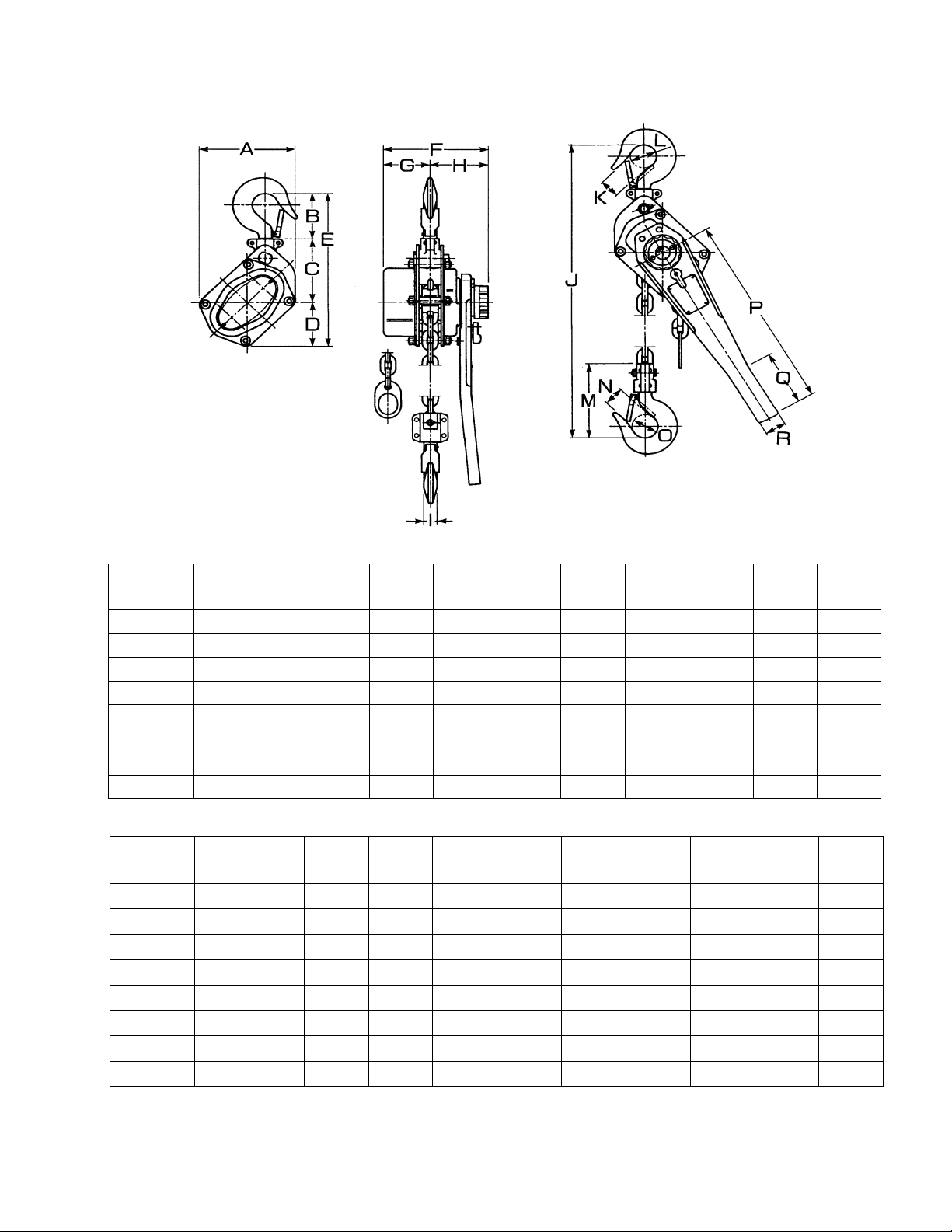
Dimensions
Stock
Number
225650 JPNX-50-5 4.8 2.55 2.79 2.55 7.91 4.32 1.18 3.14 0.59
225652 JPNX-50-15 4.8 2.55 2.79 2.55 7.91 4.32 1.18 3.14 0.59
225675 JPNX-75-5 4.96 2.75 3.3 2.67 8.74 5.86 2.44 3.42 0.62
225676 JPNX-75-15 4.96 2.75 3.3 2.67 8.74 5.86 2.44 3.42 0.62
225615 JPNX-150-5 5.74 3.5 3.62 3.03 10.15 7.08 2.95 4.13 0.82
225616 JPNX-150-15 5.74 3.5 3.62 3.03 10.15 7.08 2.95 4.13 0.82
225630 JPNX-300-5 7.59 4.13 4.33 4.01 12.48 7.49 3.66 4.33 1.1
225631 JPNX-300-15 7.59 4.13 4.33 4.01 12.48 7.49 3.66 4.33 1.1
Description A B C D E F G H I
Stock
Number
225650 JPNX-50-5 12 1.1 1.37 4.13 1.1 1.37 10.03 4.33 1.57
225652 JPNX-50-15 12 1.1 1.37 4.13 1.1 1.37 10.03 4.33 1.57
225675 JPNX-75-5 12.4 1.18 1.45 4.4 1.18 1.45 10.03 4.33 1.57
225676 JPNX-75-15 12.4 1.18 1.45 4.4 1.18 1.45 10.03 4.33 1.57
225615 JPNX-150-5 14.37 1.41 1.77 5.47 1.41 1.77 14.17 6.61 1.77
225616 JPNX-150-15 14.37 1.41 1.77 5.47 1.41 1.77 14.17 6.61 1.77
225630 JPNX-300-5 19.29 1.73 2.16 6.73 1.73 2.16 14.17 6.61 1.77
225631 JPNX-300-15 19.29 1.73 2.16 6.73 1.73 2.16 14.17 6.61 1.77
Description
J
(min.)
K L M N O P Q R
6
Prior to Operation
1. Support for the hoist may be hook, clevis
pin, trolley, or beam clamp. Whatever
method of suspension is chosen, the
support component s must be rat ed equal to,
or greater than the capacity of the lever
hoist.
2. W ith the l ev er in the up posi ti on, c heck f or a
clicking sound when the ha ndle i s rotated in
a clockwise direction. If this sound is not
present, do not use the hoi st.
3. With the lever in the up position, check fr ee
play in handle rotation. Free play is
measured by the distance the handle travels
before resistance or gearing is felt. If free
play has reached 3/4 of a turn, the friction
discs are worn and shoul d be replaced by a
WMH Tool Group authori z ed r epair station.
4. If the lever hoist has not been used for an
extended period of time, check for proper
operation before putting into service.
5. The brake mechanism must be kept clean
and free from dirt, water, and oil. Never
allow oil to penetrate the braking
mechanism. Always keep your lever hoist
clean and store i n a clean, dr y l oc ation.
6. Periodi cally apply a light coat of 30W oil to
the chain. This will create easier operation
and prolong the lif e of t he c hain.
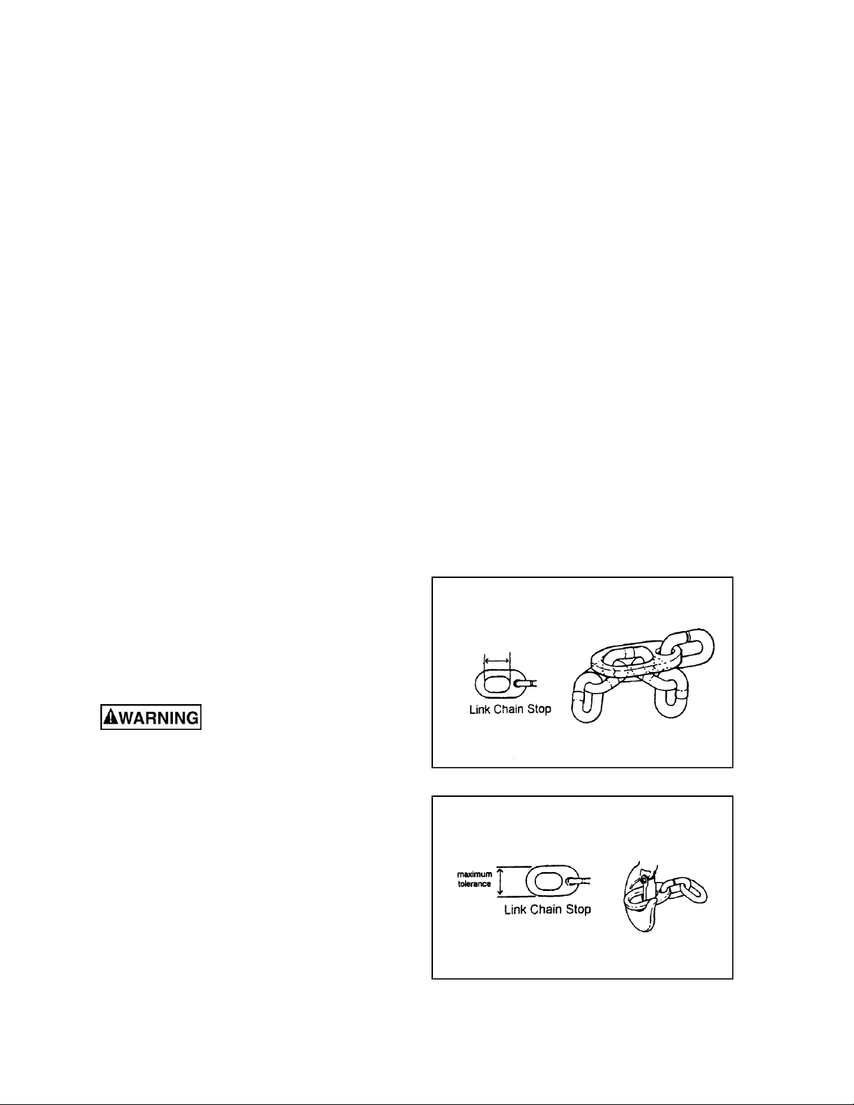
7. Check the chain for damage and elongation.
Use the chain gauge on the bottom end of
the chain as a guide. If the chain links do
not fit inside the chain gauge, as shown in
Figure 1, then the links have become
elongated and the chain must be replaced.
T h e lo ad c hai n su ppli ed wit h
your JET lever hoist is designed,
manufactured, and tested for proper fit and
durability. Over a period of time, the chain
may need to be replaced. For your own
safety, use factory replacement chain only.
Use of other th an factory replacement chain
may cause serious injury and/or damage to
the lever hoist.
8. The top and bottom hooks on your JET
lever hoist are designed to open to warn of
an overload. It i s im portant to c heck t op and
bottom hooks for proper opening. If the
safety latch no longer contacts the hook
opening, replace the hook. Another way to
check the opening is by using the chain
gauge. Position the gauge as in Figure 2.
Figure 1
Figure 2
7
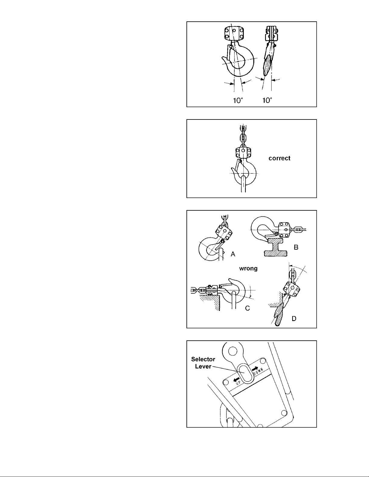
9. If the gauge does not contact both sides of
t
the hook, replace the hook. Never side
load the top or bottom hook; this
practice is dangerous and could lead to
serious injury.
10. If the vertical angle at the neck of the bottom
or top hook reaches 10°, repl ace the hook
(see Figure 3).
Operation
1. Set the top hook securel y .
2. Center load on bottom hook correctly
(Figure 4). Incorrect loading is dangerous to
he operator, the lever hoist, and the load.
Never load the hook in front of the safety
latch (A, Figure 5). Never load the hook tip
(B, Figure 5). Never load the hook off the
centerline (C, Figure 5). Never load the
hook sideways (D, Figure 5).
3. Pl ace t he select or lever on the handl e i n the
center neutral posi tion (Figure 6) so that t he
chain free-wheels. Note: Chain will only
free-wheel when there i s no load. Take up
slack by pulli ng on loose or free end, or by
turning handwheel.
Figure 3
Figure 4
4. Move sel ector lever to the up positi on (see
Figure 6). Ratchet handle to raise or pull
load. Do not overload t he lev er hoist.
5. To release or lower load, turn selector lever
on handle to the down position ( see Figure
6) and ratchet the handle.
Figure 5
Figure 6
8

Precautions
• During pulling operations, the operator
should stand near t he side of the top hook
on the opposite side of the lever. If the
hand should sli p off the l ever, the lever will
spring back away f rom the operator (Figure
7).
• During lif ting operati ons, do not stand under
the load.
• Do not use an extension on the lever (A,
Figure 8). Do not use a foot to apply
pressure to the l ev er (B, Fi gur e 8).
• Prev ent the chain from dragging over sharp
edges or corners. This will cause links to
weaken, bend, or break (Figure 9).
Figure 7
Figure 8
• W hen usi ng a wire rope sli ng, the lever hoist
must be applied al ong a strai ght line paral lel
to the surf ace on which it is resting (Figur e
10).
Figure 9
Figure 10
9
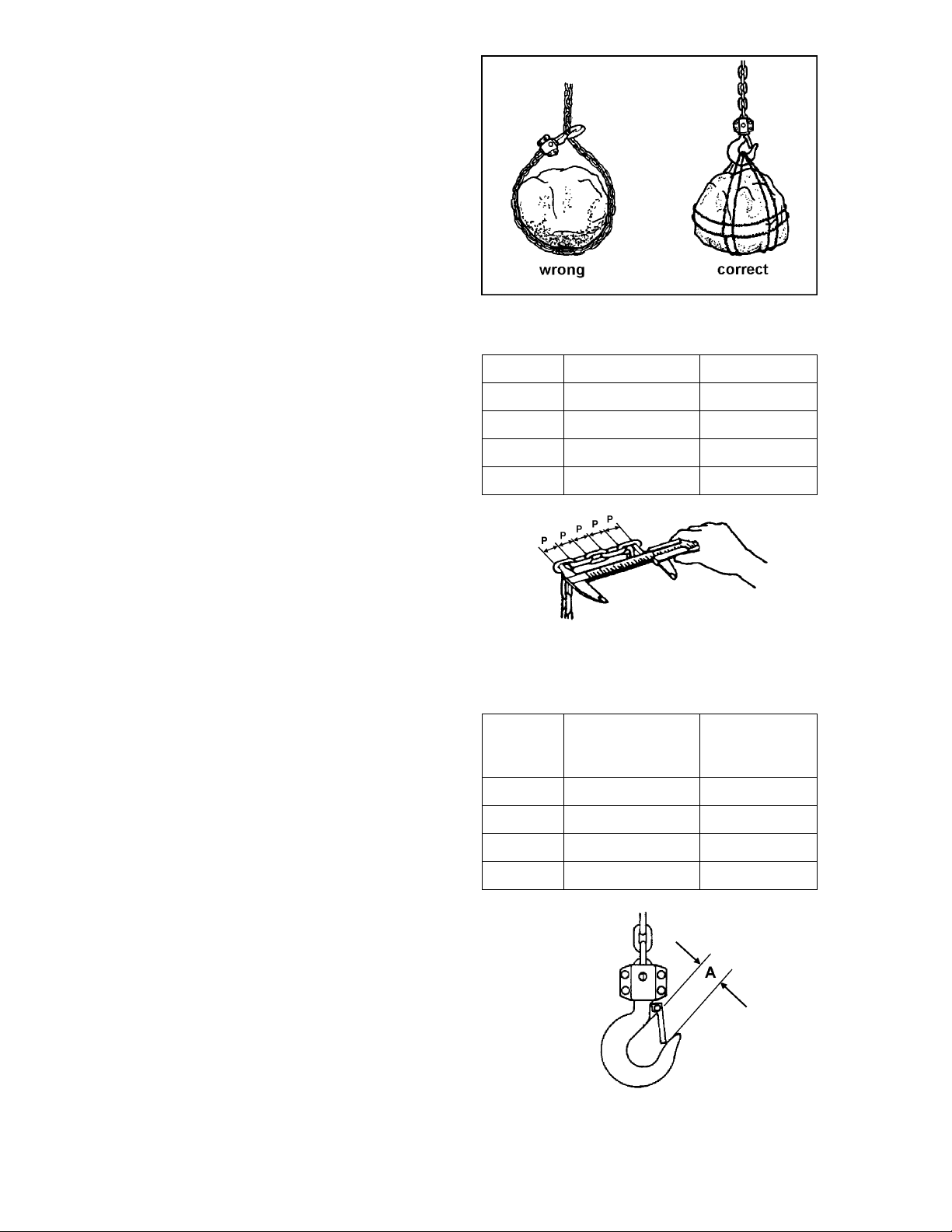
•
W
hen lifting loads, hook the load wit h sl ings.
Do not use the lever hoist chain as a
sling (Figure 11).
• Both ends of a sling or rope must be
completely on the inside of t he safety latch
before pulli ng or lifting the load. Do not put
one end on the i nside of the l atc h and leav e
the other end on the hook end out side the
latch.
Allowable Limits for Load
Chain and Hooks
Load Chain
Carefully inspect the entire load chain. As
illustrated in Figure 12, measure five
consecutiv e li nks with cali pers to f ind t he length,
Compare the resul ts with t he table i n Figure 12.
Check every three feet and especially where
excessiv e wear is indicated. Any load c hain that
shows noticeabl e deformation or heat influence
must be replaced wit h a new one.
Never extend load chain by welding a second
piece to the original.
Hooks (Top and Bottom)
Replace the hook when “A” i n Fi gure 13 is wider
than Limit A in the table. Never heat treat the
hook or attach anything to the hook by welding.
Figure 11
Capacity 5 Links Normal 5 L in ks Li mit
1/2 ton 2.95” 3.04”
3/4 ton 3.54” 3.65”
1-1/2 ton 4.72” 4.87”
3 ton 5.91” 6.08”
Figure 12
Standard
Capacity
1/2 ton 1.1” 1.21”
3/4 ton 1.18” 1.3”
1-1/2 ton 1.42” 1.56”
Throat Opening
(A)
Throat
Opening
Limit (A)
3 ton 1.73” 1.91”
Figure 13
10

Replacement Parts
Replacement part s are li sted on the f ollowing page s. To order par ts or reac h our servi ce depar tment, call
1-800-274-6848 between 7:30 a.m. and 6:00 p.m. (CST), Monday through Friday. Having the Model
Number and Serial Number of your machine available when you call will allow us to serve y ou quickly and
accurately.
11

JPNX-50
12

Parts List: JPNX-50
Note: Parts listed under eac h as sembly are parts that make up that assembly .
Index No. Part No. Description Size Qty
1...............JPNX50-1 ............... Cover........................................................... ......................................... 1
5...............JLP50-5..................Cover Side P late Ass e mbly.......................... .........................................1
................. ...............................Cover Side Plate.......................................... .........................................1
................. ...............................Stay Bolt...................................................... .........................................3
................. ...............................Race............................................................ .........................................1
7...............JLP50-7..................Load Shaft................................................... .........................................1
9...............JLP50-9..................Guide Block................................................. .........................................2
10.............JLP50-10 ................ Stripper........................................................ .........................................1
13.............JLP75-13 ................ Pawl Spring (1/2, 3/4 Ton) ........................... .........................................2
14.............JLP50-14 ................ Pawl ............................................................ .........................................2
15.............JLP75-15 ................ Snap Ring (1/2, 3/4 Ton) ..............................8 mm ................................2
16.............JLP50-16 ................ Lever Side Plate Assembly.......................... .........................................1
................. ...............................Lever Side Plate.......................................... .........................................1
................. ...............................Race............................................................ .........................................1
................. ...............................Pawl Pin...................................................... .........................................2
17.............JLP50-17 ................ Disc Hub...................................................... .........................................1
18.............JLP75-18 ................ Spring (1/2, 3/4, 1-1/2 Ton).......................... .........................................1
19.............JLP50-19 ................ Friction Disc................................................. .........................................2
20.............JLP50-20 ................ Ratchet Disc................................................ .........................................1
22.............JPNX50-22..............Brake Cover Assembly ................................ .........................................1
................. ...............................Brake Cover ................................................ .........................................1
................. ...............................Handle Case................................................ .........................................1
................. ...............................Nut .............................................................. .........................................2
................. ...............................Bushing....................................................... .........................................1
23.............JLP50-23 ................ Change Over Gear ...................................... .........................................1
24.............JPNX75-24..............Lever Handle Assembly (1/2, 3/ 4 Ton) ......... .........................................1
................. ...............................Lever Handle............................................... .........................................1
................. ...............................Selector Lever............................................. ......................................... 1
................. ...............................Change Over Shaft...................................... .........................................1
................. ...............................Cover........................................................... .........................................1
................. ...............................Rivet............................................................3 x 12 mm.........................1
................. ...............................Bolt.............................................................. .........................................2
................. ...............................Spring Seat.................................................. .........................................1
25.............JLP75-25 ................ Change Over Pawl (1/2, 3/4 Ton)................. .........................................1
26.............JLP75-26 ................ Spring Shaft (1/2, 3/4 Ton)........................... .........................................1
27.............JLP75-27 ................ Spring (1/2, 3/4 Ton).................................... .........................................1
28.............JPNX75-28..............Handwheel (1/2, 3/ 4 Ton) ............................. .........................................1
29.............JPNX50-29..............Warning Label............................................. ......................................... 1
29A...........JPNX50-29A........... ID Label....................................................... .........................................1
30.............JLP75-30 ................ Chain Stop (1/2, 3/4 Ton)............................. .........................................1
31.............JLP75-31 ................ Hex Nut (1/2, 3/4 Ton).................................M8....................................6
32.............JLP75-32 ................ Lock Washer (1/2, 3/4 Ton)..........................M8....................................6
32A...........JLP75-32A.............. Fl at Washer (1/2, 3/4 Ton)...........................M8 ....................................6
33.............JLP75-33 ................ Hex Nut (1/2, 3/4 Ton).................................M6....................................2
34.............JLP75-34 ................ Lock Washer (1/2, 3/4 Ton)..........................M8....................................2
34A...........JLP75-34A.............. Fl at Washer (1/2, 3/4 Ton)...........................M6 ....................................4
35.............JLP75-35 ................ Castl e Nut (1/2, 3/4 Ton)..............................M10..................................1
36.............JLP75-3 6................ Split Pin (1/2, 3/4 Ton).................................2.5 x 20 mm......................1
37.............JLP75-3 7................ Rivet (1/2 to 6 To n )......................................2.5 x 6 mm........................4
38.............JPNX50-38..............Rivet (1/2 Ton).............................................2 x 5 mm...........................4
40.............JLP50-40 ................ Top Hook Assembly..................................... .........................................1
................. ...............................Top Hook..................................................... .........................................1
................. ...............................Safety Latch ................................................ .........................................1
................. ...............................Double Spri ng.............................................. .........................................1
................. ...............................Rivet............................................................3 x 16 mm.........................1
13

Index No. Part No. Description Size Qty
................. ...............................Top Hook Block........................................... .........................................2
................. ...............................Rivet............................................................5 x 20 mm.........................2
41.............JLP50-41 ................ Top Hook Shaft............................................ ......................................... 1
43.............JLP50-43 ................ Bottom Hook Assembly................................ .........................................1
................. ...............................Bottom Hook................................................ .........................................1
................. ...............................Safety Latch ................................................ .........................................1
................. ...............................Double Spri ng.............................................. .........................................1
................. ...............................Rivet............................................................3 x 16 mm.........................1
................. ...............................Bottom Hook Block...................................... .........................................2
................. ...............................Rivet............................................................5 x 20 mm.........................4
43A...........JLP50-43A.............. Bottom Hook Shaft....................................... .................................. .......1
43C ..........JLP50-43C.............. Castle Nut....................................................M6....................................1
43D ..........JLP50-43 D.............. Spl it Pin.......................................................1.6 x 14 mm......................1
50.............JLP75-50 ................ Hex Cap Screw (1/2, 3/4 Ton)......................M6 x 12.............................2
51.............JLP75-51 ................ Lock Washer (1/2, 3/4 Ton)..........................M6....................................2
52.............JLP50-52 ................ Special Pin.................................................. ......................................... 1
100...........JLP50-100 ..............Safety Latch Kit ........................................... .........................................1
................. ...............................Safety Latch ................................................ .........................................1
................. ...............................Double Spri ng.............................................. .........................................1
................. ...............................Rivet............................................................3 x 16 mm.........................1
104...........121006.................... Load Chai n* ( 1/2 Ton)..................................Ø 5 mm.............................1
* Specify required chain length when ordering.
Note: Top and bottom hooks are sold as an assem bly only.
14

JPNX-75/150/300
15

Parts List: JPNX-75
Note: Parts listed under eac h as sembly are parts that make up that assembly.
Index No. Part No. Description Size Qty
1...............JPNX75-1 ............... Gear Case Assembly................................... .........................................1
................. ...............................Gear Case................................................... .........................................1
................. ...............................Bushing....................................................... .........................................1
2...............JLP75-2..................Spur Gear Assembly .................................... .........................................2
................. ...............................Spur Gear.................................................... .........................................2
................. ...............................Pinion Gear ................................................. .........................................2
3...............JLP75-3..................Driving Shaft................................................ .........................................1
4...............JLP75-4..................Load Gear ................................................... .........................................1
5...............JLP75-5..................Gear Side Plate Assembly........................... .........................................1
................. ...............................Gear Side Plate........................................... .........................................1
................. ...............................Gear Side Plate........................................... .........................................1
................. ...............................Stay Bolt...................................................... .........................................3
................. ...............................Bushing....................................................... .........................................2
................. ...............................Race “A”...................................................... .........................................1
6...............JLP75-6..................Load Sheave ............................................... .........................................1
8...............JLP75-8..................Guide Block................................................. .........................................1
9...............JLP75-9..................Guide Roll er ................................................ ......................................... 1
10.............JLP75-10 ................ Stripper........................................................ .........................................1
11.............JLP75-11 ................ Roller Kit (34 Rollers)...................................3 x 5 mm...........................1
12.............JLP75-12 ................ Bearing Race............................................... .........................................1
13.............JLP75-13 ................ Pawl Spring (1/2, 3/4 Ton) ........................... .........................................2
14.............JLP75-14 ................ Pawl ............................................................ .........................................2
15.............JLP75-15 ................ Snap Ring (1/2, 3/4 Ton) ..............................8mm.................................2
16.............JLP75-16 ................ Lever Side Plate Assembly.......................... .........................................1
................. ...............................Lever Side Plate.......................................... .........................................1
................. ...............................Race “B”...................................................... .........................................1
................. ...............................Pawl Pin...................................................... .........................................2
17.............JLP75-17 ................ Disc Hub...................................................... .........................................1
18.............JLP75-18 ................ Spring (1/2, 3/4, 1-1/2 Ton).......................... .........................................1
19.............JLP75-19 ................ Friction Disc................................................. .........................................2
20.............JLP75-20 ................ Ratchet Disc................................................ .........................................1
21.............JLP75-21 ................ Feed Gear................................................... .........................................1
22.............JPNX75-22..............Brake Cover Assembly ................................ .........................................1
................. ...............................Brake Cover ................................................ .........................................1
................. ...............................Handle Case................................................ .........................................1
................. ...............................Nut .............................................................. .........................................2
................. ...............................Bushing....................................................... .........................................1
23.............JLP75-23 ................ Change Over Gear ...................................... .........................................1
24.............JPNX75-24..............Lever Handle Assembly (1/2, 3/ 4 Ton) ......... .........................................1
................. ...............................Lever Handle............................................... .........................................1
................. ...............................Selector Lever............................................. ......................................... 1
................. ...............................Change Over Shaft...................................... .........................................1
................. ...............................Cover........................................................... .........................................1
................. ...............................Rivet............................................................3 x 12 mm.........................1
................. ...............................Bolt.............................................................. .........................................2
................. ...............................Spring Seat.................................................. .........................................1
25.............JLP75-25 ................ Change Over Pawl (1/2, 3/4 Ton)................. .........................................1
26.............JLP75-26 ................ Spring Shaft (1/2, 3/4 Ton)........................... .........................................1
27.............JLP75-27 ................ Spring (1/2, 3/4 Ton).................................... .........................................1
28.............JPNX75-28..............Handwheel (1/2, 3/ 4 Ton) ............................. .........................................1
29.............JPNX75-29..............Warning Label............................................. ......................................... 1
29A...........JPNX75-29A........... ID Label....................................................... .........................................1
30.............JLP75-30 ................ Chain Stop (1/2, 3/4 Ton)............................. .........................................1
31.............JLP75-31 ................ Hex Nut (1/2, 3/4 Ton).................................M8....................................6
32.............JLP75-32 ................ Lock Washer (1/2, 3/4 Ton)..........................M8....................................6
32A...........JLP75-32A.............. Fl at Washer (1/2, 3/4 Ton)...........................M8 ....................................6
16

Index No. Part No. Description Size Qty
33.............JLP75-33 ................ Hex Nut (1/2, 3/4 Ton).................................M6....................................2
34.............JLP75-34 ................ Lock Washer (1/2, 3/4 Ton)..........................M6....................................2
34A...........JLP75-34A.............. Fl at Washer (1/2, 3/4 Ton)...........................M6 ....................................4
35.............JLP75-35 ................ Castl e Nut (1/2, 3/4 Ton)..............................M10..................................1
36.............JLP75-3 6................ Split Pin (1/2, 3/4 Ton).................................2.5 x 20 mm......................1
37.............JLP75-3 7................ Rivet (1/2 to 6 To n )......................................2.5 x 6 mm........................6
40.............JLP75-40 ................ Top Hook Assembly..................................... .........................................1
................. ...............................Top Hook..................................................... .........................................1
................. ...............................Safety Latch ................................................ .........................................1
................. ...............................Double Spri ng.............................................. .........................................1
................. ...............................Rivet............................................................3 x 16 mm.........................1
................. ...............................Top Hook Block........................................... .........................................2
................. ...............................Rivet............................................................5 x 20 mm.........................2
41.............JLP75-41 ................ Top Hook Shaft............................................ ......................................... 1
43.............JLP75-43 ................ Bottom Hook Assembly................................ .........................................1
................. ...............................Bottom Hook................................................ .........................................1
................. ...............................Safety Latch ................................................ .........................................1
................. ...............................Double Spri ng.............................................. .........................................1
................. ...............................Rivet............................................................3 x 16 mm.........................1
................. ...............................Bottom Hook Block...................................... .........................................2
................. ...............................Rivet............................................................5 x 20 mm.........................4
43A...........JLP75-43A.............. Bottom Hook Shaft....................................... .................................. .......1
43C ..........JLP75-43C.............. Castle Nut....................................................M6....................................1
43D ..........JLP75-43 D.............. Spl it Pin.......................................................1.6 x 14 mm......................1
50.............JLP75-5 0................ Hex Cap Screw............................................M6 x 12.............................2
51.............JLP75-5 1................ Lock Washe r ................................................M6....................................2
58.............JLP75-58 ................ Snap Ring....................................................28 mm ..............................1
100...........JLP75-100 ..............Safety Latch Kit ........................................... .........................................1
................. ...............................Safety Latch ................................................ .........................................1
................. ...............................Double Spri ng.............................................. .........................................1
................. ...............................Rivet............................................................3 x 16 mm.........................1
104...........121007.................... Load Chai n* ( 3/4 Ton)..................................Ø 6 mm.............................1
* Specify required chain length when ordering.
Note: Top and bottom hooks are sold as an assem bly only.
17

Parts List: JPNX-150
Note: Parts listed under eac h as sembly are parts that make up that assembly.
Index No. Part No. Description Size Qty
1...............JPNX150-1..............Gear Case Assembly................................... .........................................1
................. ...............................Gear Case................................................... .........................................1
................. ...............................Bushing....................................................... .........................................2
2...............JLP150-2 ................ Spur Gear Assembly.................................... .........................................2
................. ...............................Spur Gear.................................................... .........................................2
................. ...............................Pinion Gear ................................................. .........................................2
3...............JLP150-3 ................ Driving Shaft................................................ .........................................1
4...............JLP150-4 ................ Load Gear ................................................... .........................................1
5...............JLP150-5 ................ Gear Side Plate Assembly........................... .........................................1
................. ...............................Gear Side Plate........................................... .........................................1
................. ...............................Stay Bolt...................................................... .........................................3
................. ...............................Bushing....................................................... .........................................2
................. ...............................Race “A”...................................................... .........................................1
6...............JLP150-6 ................ Load Sheave ............................................... .........................................1
8...............JLP150-8 ................ Guide Block................................................. .........................................1
9...............JLP150-9 ................ Guide Roller................................................ .........................................1
10.............JLP150-10 ..............Stripper........................................................ .........................................1
11.............JLP150-11 ..............Roller Kit (37 Rollers)...................................3 x 6 mm........................... 1
12.............JLP150-12 ..............Bearing Race............................................... .........................................1
13.............JLP150-13 ..............Pawl Spring (1-1/2, 3, 6 Ton) ....................... .........................................2
14.............JLP150-14 ..............Pawl (1-1/2, 3, 6 Ton) .................................. .........................................2
15.............JLP150-15 .............. Snap Ring (1-1/2, 3, 6 Ton)......................... .........................................2
16.............JLP150-16 ..............Lever Side Plate Assembly.......................... .........................................1
................. ...............................Lever Side Plate.......................................... .........................................1
................. ...............................Race “B”...................................................... .........................................1
................. ...............................Pawl Pin...................................................... .........................................2
17.............JLP150-17 ..............Disc Hub...................................................... .........................................1
18.............JLP75-18 ................ Spring (1/2, 3/4, 1-1/2 Ton).......................... .........................................1
19.............JLP150-19 ..............Friction Disc................................................. .........................................2
20.............JLP150-20 ..............Ratchet Disc................................................ .........................................1
21.............JLP150-21 ..............Feed Gear................................................... .........................................1
22.............JPNX150-22............ Brake Cover Assembly................................ .........................................1
................. ...............................Brake Cover ................................................ .........................................1
................. ...............................Handle Case................................................ .........................................1
................. ...............................Nut .............................................................. .........................................2
................. ...............................Bushing....................................................... .........................................1
23.............JLP150-23 ..............Change Over Gear (1-1/2, 3, 6 Ton)............. .........................................1
24.............JPNX150-24............ Lever Handle Assembly (1-1/2, 3 Ton)......... .........................................1
................. ...............................Lever Handle............................................... .........................................1
................. ...............................Selector Lever............................................. ......................................... 1
................. ...............................Change Over Shaft...................................... .........................................1
................. ...............................Cover........................................................... .........................................1
................. ...............................Rivet............................................................3 x 12 mm.........................1
................. ...............................Screw.......................................................... .........................................2
................. ...............................Spring Seat.................................................. .........................................1
25.............JLP150-25 ..............Change Over Pawl (1-1/ 2, 3, 6 Ton)............. .........................................1
26.............JLP150-26 ..............Spring Shaft (1-1/2, 3, 6 Ton)....................... .........................................1
27.............JLP150-27 ..............Spring (1-1/2, 3, 6 Ton)................................ .........................................1
28.............JPNX150-28............ Handwheel (1-1/2, 3 Ton) ............................ .........................................1
29.............JPNX150-29............ Warning Label............................................. .........................................1
29A...........JPNX150-29A ......... ID Label....................................................... .........................................1
30.............JLP150-30 ..............Chain Stop................................................... ......................................... 1
31.............JLP150-31 ..............Hex Nut.......................................................M10..................................6
32.............JLP150-32 ..............Lock Wash e r ................................................M10..................................6
32A...........JLP150-32A ............ Fla t Washer.................................................M1 0..................................6
33.............JLP150-33 ..............Hex Nut (1-1/2, 3, 6 Ton).............................M8 ....................................2
18

Index No. Part No. Description Size Qty
34.............JLP150-34 ..............Lock Washer (1-1/2, 3, 6 Ton)......................M8....................................2
34A...........JLP150-34A ............ Flat Washer (1-1/2, 3, 6 Ton).......................M8....................................4
35.............JLP150-35 ..............Castle Nut (1-1/2, 3, 6 Ton)..........................M12..................................1
36.............JLP150-36 ..............Split Pin (1-1/2, 3, 6 Ton).............................2.5 x 25 mm......................1
37.............JLP75-3 7................ Rivet (1/2 to 6 To n )......................................2.5 x 6 mm........................6
40.............JLP150-40 ..............Top Hook Assembly..................................... .........................................1
................. ...............................Top Hook..................................................... .........................................1
................. ...............................Safety Latch ................................................ .........................................1
................. ...............................Double Spri ng.............................................. .........................................1
................. ...............................Rivet............................................................4 x 18 mm.........................1
................. ...............................Top Hook Block........................................... .........................................2
................. ...............................Rivet............................................................6 x 24 mm.........................2
41.............JLP150-41 ..............Top Hook Shaft............................................ .........................................1
43.............JLP150-43 ..............Bottom Hook Assembly................................ .........................................1
................. ...............................Bottom Hook................................................ .........................................1
................. ...............................Safety Latch ................................................ .........................................1
................. ...............................Double Spri ng.............................................. .........................................1
................. ...............................Rivet............................................................4 x 18 mm.........................1
................. ...............................Bottom Hook Block...................................... .........................................2
................. ...............................Rivet............................................................6 x 24 mm.........................4
43A...........JLP150-43A ............ Bottom Hook Shaft....................................... .........................................1
43C ..........JLP150-43C............Castle Nut....................................................M8....................................1
43D ..........JLP150-43D............Split Pin.......................................................2 x 16 mm.........................1
50.............JLP150-50 ..............Hex Cap Screw (1-1/2, 3, 6 Ton)..................M8 x 16.............................2
51.............JLP150-51 ..............Lock Washer (1-1/2, 3, 6 Ton)......................M8....................................2
58.............JLP150-58 ..............Snap Ring....................................................34 mm..............................1
100...........JLP150-100............. Safety Latch Kit........................................... .........................................1
................. ...............................Safety Latch ................................................ .........................................1
................. ...............................Double Spri ng.............................................. .........................................1
................. ...............................Rivet............................................................4 x 18 mm.........................1
104...........121002.................... Load Chai n* ( 1- 1/2 Ton)...............................Ø 8 mm.............................1
* Specify required chain length when ordering.
Note: Top and bottom hooks are sold as an assem bly only.
19

Parts List: JPNX-300
Note: Parts listed under eac h as sembly are parts that make up that assembly.
Index No. Part No. Description Size Qty
1...............JPNX300-1..............Gear Case Assembly (3 Ton)....................... .........................................1
................. ...............................Gear Case................................................... .........................................1
................. ...............................Bushing....................................................... .........................................2
2...............JLP300-2 ................ Spur Gear Assembly (3, 6 Ton).................... .........................................2
................. ...............................Spur Gear.................................................... .........................................2
................. ...............................Pinion Gear ................................................. .........................................2
3...............JLP300-3 ................ Driving Shaft (3, 6 Ton)................................ .........................................1
4...............JLP300-4 ................ Load Gear (3, 6 Ton) ................................... .........................................1
5...............JLP300-5 ................ Gear Side Plate Assembly (3, 6 Ton)........... .........................................1
................. ...............................Gear Side Plate........................................... .........................................1
................. ...............................Stay Bolt...................................................... .........................................3
................. ...............................Bushing....................................................... .........................................2
................. ...............................Race “A”...................................................... .........................................1
6...............JLP300-6 ................ Load Sheave (3, 6 Ton) ............................... .........................................1
8...............JLP300-8 ................ Guide Block (3, 6 Ton)................................. .........................................1
9...............JLP300-9 ................ Guide Roller (3, 6 Ton)................................ .........................................1
10.............JLP300-10 ..............Stripper (3, 6 Ton)........................................ .........................................1
11.............JLP300-11 ..............Roller Kit (3, 6 Ton) (24 Rollers)...................5 x 6 mm...........................1
12.............JLP300-12 ..............Bearing Race (3, 6 Ton)............................... .........................................1
13.............JLP150-13 ..............Pawl Spring (1-1/2, 3, 6 Ton) ....................... .........................................2
14.............JLP150-14 ..............Pawl (1-1/2, 3, 6 Ton) .................................. .........................................2
15.............JLP150-15 ..............Snap Ring (1-1/2, 3, 6 Ton).......................... .........................................2
16.............JLP300-16 ..............Lever Side Plate Assembly (3, 6 Ton).......... ......................................... 1
................. ...............................Lever Side Plate.......................................... .........................................1
................. ...............................Race “B”...................................................... .........................................1
................. ...............................Pawl Pin...................................................... .........................................2
17.............JLP300-17 ..............Disc Hub (3, 6 Ton)...................................... .........................................1
18.............JLP300-18 ..............Spring (3, 6 Ton).......................................... .........................................1
19.............JLP300-19 ..............Friction Disc (3, 6 Ton)................................. .........................................2
20.............JLP300-20 ..............Ratchet Disc (3, 6 Ton)................................ .........................................1
21.............JLP300-21 ..............Feed Gear (3, 6 Ton)................................... .........................................1
22.............JPNX300-22............ Brake Cover Assembly (3 Ton).................... .........................................1
................. ...............................Brake Cover ................................................ .........................................1
................. ...............................Handle Case................................................ .........................................1
................. ...............................Nut .............................................................. .........................................2
................. ...............................Bushing....................................................... .........................................1
23.............JLP150-23 ..............Change Over Gear (1-1/2, 3, 6 Ton)............. .........................................1
24.............JPNX150-24............ Lever Handle Assembly (1-1/2, 3 Ton)......... .........................................1
................. ...............................Lever Handle............................................... .........................................1
................. ...............................Selector Lever............................................. ......................................... 1
................. ...............................Change Over Shaft...................................... .........................................1
................. ...............................Cover........................................................... .........................................1
................. ...............................Rivet............................................................3 x 12 mm.........................1
................. ...............................Bolt.............................................................. .........................................2
................. ...............................Spring Seat.................................................. .........................................1
25.............JLP150-25 ..............Change Over Pawl (1-1/ 2, 3, 6 Ton)............. .........................................1
26.............JLP150-26 ..............Spring Shaft (1-1/2, 3, 6 Ton)....................... .........................................1
27.............JLP150-27 ..............Spring (1-1/2, 3, 6 Ton)................................ .........................................1
28.............JPNX150-28............ Handwheel (1-1/2, 3 Ton) ............................ .........................................1
29.............JPNX300-29............ Warning Label............................................. .........................................1
29A...........JPNX300-29A ......... ID Label....................................................... .........................................1
30.............JLP300-30 ..............Chain Stop (3, 6 Ton)................................... .........................................1
31.............JLP300-31 ..............Hex Nut (3, 6 Ton).......................................M12..................................6
32.............JLP300-32 ..............Lock Washer (3, 6 Ton)................................M12 ..................................6
32A...........JLP300-32A ............ Flat Washer (3, 6 Ton) .................................M12..................................6
33.............JLP150-33 ..............Hex Nut (1-1/2, 3, 6 Ton).............................M8 ....................................2
20

Index No. Part No. Description Size Qty
34.............JLP150-34 ..............Lock Washer (1-1/2, 3, 6 Ton)......................M8....................................2
34A...........JLP150-34A ............ Flat Washer (1-1/2, 3, 6 Ton).......................M8....................................4
35.............JLP150-35 ..............Castle Nut (1-1/2, 3, 6 Ton)..........................M12..................................1
36.............JLP150-36 ..............Split Pin (1-1/2, 3, 6 Ton).............................2.5 x 25 mm......................1
37.............JLP75-3 7................ Rivet (1/2 to 6 To n )......................................2.5 x 6 mm........................6
40.............JLP300-40 ..............Top Hook Assembly..................................... .........................................1
................. ...............................Top Hook..................................................... .........................................1
................. ...............................Safety Latch ................................................ .........................................1
................. ...............................Double Spri ng.............................................. .........................................1
................. ...............................Rivet............................................................4 x 22 mm.........................1
................. ...............................Top Hook Block........................................... .........................................2
................. ...............................Rivet............................................................8 x 28 mm.........................2
41.............JLP300-41 ..............Top Hook Shaft (3, 6 Ton)............................ .........................................1
43.............JLP300-43 ..............Bottom Hook Assembly................................ .........................................1
................. ...............................Bottom Hook................................................ .........................................1
................. ...............................Safety Latch ................................................ .........................................1
................. ...............................Double Spri ng.............................................. .........................................1
................. ...............................Rivet............................................................4 x 22 mm.........................1
................. ...............................Bottom Hook Block...................................... .........................................2
................. ...............................Rivet............................................................8 x 28 mm.........................4
43A...........JLP300-43A ............ Bottom Hook Shaft....................................... .........................................1
43C ..........JLP300-43C............Castle Nut....................................................M12..................................1
43D ..........JLP300-43D............Split Pin.......................................................2.5 x 2.5 mm.....................1
50.............JLP150-50 ..............Hex Cap Screw (1-1/2, 3, 6 Ton)..................M8 x 16.............................2
51.............JLP150-51 ..............Lock Washer (1-1/2, 3, 6 Ton)......................M8....................................2
58.............JLP300-58 ..............Snap Ring (3, 6 Ton)....................................45 mm..............................1
100...........JLP300-100............. Safety Latch Kit........................................... .........................................1
................. ...............................Safety Latch ................................................ .........................................1
................. ...............................Double Spri ng.............................................. .........................................1
................. ...............................Rivet............................................................4 x 22 mm.........................1
104...........121008.................... Load Chai n* ( 3 Ton).....................................Ø 10 mm...........................1
* Specify required chain length when ordering.
Note: Top and bottom hooks are sold as an assem bly only.
21

NOTES
22

Test Certificate
Model No. JPNX-
Serial No.
Rated Load Ton
Test Load Ton
Lift (ft.)
Judgment Passed
Inspected by
Date
23

WMH Tool Gr ou p
2420 Vantage Drive
Elgin, Illinois 60123
Phone: 800-274-6848
www.wmhtoolgroup.com
24
 Loading...