

Page 1

This .pdf document is bookmarked
Operating Instructions and Parts Manual
Oscillating Spindle Sander
Model JOVS-10
WALTER MEIER (Manuf acturing) Inc.
427 New Sanford Road
LaVergne, Tennessee 37086 Part No. M- 708411
Ph.: 800-274-6848 Revision B2 11/2010
www.walt er meier.c om Copyright © 2010 Walt er Meier (M anufacturi ng) Inc.
Page 2

W arranty and Service
Walter Meier (Manufacturing) Inc., warrants every product it sells. If one of our tools needs service or repair, one of
our Authorized Service Centers located throughout the United States can give you quick service. In most cases, any
of these Walter Meier Authorized Service Centers can authorize warranty repair, assist you in obtaining parts, or
®
perform routine maintenance and major repair on your JET
your area call 1-800-274-6848.
MORE INFORMATION
Walter Meier is consistently adding new products to the line. For complete, up-to-date product information, check with
your local Walter Meier distributor, or visit waltermeier.com.
WARRANTY
JET products carry a limited warranty which varies in duratio n based upon the product (MW = Metalworking, WW =
Woodworking).
WHAT IS COVERED?
This warranty covers any defects in workmanship or materials subject to the e xceptions stated below. Cutting tools,
abrasives and other consumables are excluded from warranty coverage.
WHO IS COVERED?
This warranty covers only the initial purchaser of the product.
WHAT IS THE PERIOD OF COVERAGE?
The general JET warranty lasts for the time period specified in the product literature of each product.
WHAT IS NOT COVERED?
Five Year Warranties do not cover woodworking (WW) products used for commercial, industrial or educational
purposes. Woodworking products with Five Year Warranties that are used for commercial, industrial or education
purposes revert to a One Year Warranty. This warranty does not cover defects due directly or indirectly to misuse,
abuse, negligence or accidents, normal wear-and-tear, improper repair or alterations, or lack of maintenance.
HOW TO GET SERVICE
The product or part must be returned for examination, postage prepaid, to a location designated by us. For the name
of the location nearest you, please call 1-800-274-6848.
You must provide proof of initial purchase date and an explanation of the complaint must accompany the
merchandise. If our inspection discloses a defect, we will repair or replace the product, or refund the purchase price,
at our option. We will return the repaired product or replacement at our expense unless it is determined by us that
there is no defect, or that the defect resulted from causes not within the scope of our warranty in which case we will,
at your direction, dispose of or return the product. In the event you choose to have the product returned, you will be
responsible for the shipping and handling costs of the return.
HOW STATE LAW APPLIES
This warranty gives you specific legal rights; you may also have other rights which vary from state to state.
LIMITATIONS ON THIS WARRANTY
WALTER MEIER (MANUFACTURING) INC., LIMITS ALL IMPLIED WARRANTIES TO THE PERIOD OF THE
LIMITED WARRANTY FOR EACH PRODUCT. EXCEPT AS STATED HEREIN, ANY IMPLIED WARRANTIES OR
MERCHANTABILITY AND FITNESS ARE EXCLUDED. SOME ST ATES DO NOT ALLOW LIMITATIONS ON HOW
LONG THE IMPLIED WARRANTY LASTS, SO THE ABOVE LIMITATION MAY NOT APPLY TO YOU.
WALTER MEIER SHALL IN NO EVENT BE LIABLE FOR DEATH, INJURIES TO PERSONS OR PROPERTY, OR
FOR INCIDENTAL, CONTINGENT, SPECIAL, OR CONSEQUENTIAL DAMAGES ARISING FROM THE USE OF
OUR PRODUCTS. SOME STATES DO NOT ALLOW THE EXCLUSION OR LIMITATION OF INCIDENTAL OR
CONSEQUENTIAL DAMAGES, SO THE ABOVE LIMITATION OR EXCLUSION MAY NOT APPLY TO YOU.
Walter Meier sells through distributors only. The specifications in Walter Meier catalogs are given as general
information and are not binding. Members of Walter Meier reserve the right to effect at any time, without prior notice,
those alterations to parts, fittings, and accessory equipment which they may deem necessary for any reason
®
whatsoever. JET
branded products are not sold in Canada by Walter Meier.
tools. For the name of an Authorized Service Center in
2
Page 3

Table of Contents
Warranty and Service..........................................................................................................................2
Table of Contents ...............................................................................................................................3
Warn in g .............................................................................................................................................4
Grounding Instructions ........................................................................................................................6
In trodu ction ........................................................................................................................................7
Spe cifi cation s .....................................................................................................................................7
Unpacking ..........................................................................................................................................8
Contents of the Shipping Container ..................................................................................................8
Mounting Sanding S leeves...............................................................................................................9
Install ing Sa nding Assemblies ..........................................................................................................9
Removing Sanding Assemblies ........................................................................................................9
Table Insert................................................................................................................................... 10
Sanding Assembly 90° to Table ...................................................................................................... 10
Replacing Sanding Sleeve ............................................................................................................. 11
Dust Collection ................................................................................................................................. 11
Mai ntenan ce .................................................................................................................................... 11
Replacement Parts ........................................................................................................................... 12
Brea k d o wn for the JOVS-10 O s c illating Spindle Sander ................................................................... 13
Parts List for the JOVS-10 Oscillating Spindle Sander...................................................................... 14
Sanding Assemblies ...................................................................................................................... 16
Parts List for Sanding Assemblies .................................................................................................. 17
Electrical Connect io ns....................................................................................................................... 18
3
Page 4

V
Warning
Wear eye prot ect ion.
Always keep guards in place and in proper operating condition. Do not oper at e t he machine
without the guards f or any reason.
This sander is intended to be used with wood and wood products only. Use of this sander and a
dust collector wit h metal products is a potential fire hazar d.
Support the workpiece adequately at all times during operation; mainta in co nt r ol of t he work
at all times.
• REMO VE ADJUSTING KEYS AND WREN CHES. Form a habit of checking to see that keys and
adjusting wrenches are remo ved fr om the machine before turning it on.
• KEEP THE W O RK AREA CLE AN. Cluttered ar eas and benches invit e accidents.
• DON’ T USE IN A DANG EROUS ENVIRO NMENT. Don’t use pow er t ools in damp or wet locations,
or expose them to rain. Keep work area well lighted.
• KEEP CHI LDREN AWAY. All visitors should be kept a safe distance from the work area.
• MAKE THE WO RKSHOP KIDPROO F w ith padlocks, master swat ches, or by removing starter keys.
• DON’ T FO RCE THE MACHINE. It will d o the job bet ter a nd sa fer at the rat e for which it was
designed.
• USE THE RIGHT TOOL. Don’t force a machine or attachment to do a job for which it was not
designed.
• USE THE PRO PER EXTENSION CORD. M ake sure your extension cord is in good conditio n. When
using an extension cord, be sure to use one heavy enough to carry the current your machine will
dra w. An under s ized cor d will caus e a d rop in the line volt age r esulting in power loss and
overheating. The table followi ng shows t he correct s ize to use depending on the cord lengt h and
nameplate ampere rat ing. If in doubt, use the next heavier ga uge. Remember, t he smaller the gauge
number, the heavier the cord.
olts Total Length of Cord in Feet
120V 25 ft. 50 ft.
AWG
16 14
• WE AR PROP ER APPAREL. Do not wear loose clothing, gloves, neckties, r ings, bracelets, or other
jewelry which may get caug ht in moving parts. Nonslip footwear is recommended. Wear pr ot ec t ive
hair covering t o cont ai n l ong hair.
• ALW AYS USE SAFETY G LASSES. Also use face or dust masks if the cutting operation is dusty.
Everyday eyeglasses o nly have impact r esist ant lenses; t hey are not safet y glasses.
• DON’T OVERREACH. Keep proper footing and balance at all times.
• MAINTAIN TOO LS W ITH CARE. Keep tools sharp and clean for best and safest perfor mance.
Follow instructions f or lubricating and c hangi ng accessories.
• ALWAYS DISCO NNECT THE MACHINE FROM THE POWER SO URCE BEFORE SERVICING.
• REDUCE THE R ISK OF UNINTENTIONAL START ING. Make sure the switch is in the off position
before pluggi ng in.
4
Page 5

• USE RECOMM ENDED ACCE SSORI E S. The use of acces sor ies and attachme nts not
recommended by JET may ca use hazards or r isk of injury to persons.
• NEVER S TAND ON A MACHIN E. Serious injury could occur if the machine is tipped.
• CHECK DAMAG ED PART S. Before further use of the machine, a guard or ot her part that is
damaged should be caref ully checked to determine that it will oper ate properly and perform its
intended function - check for alignme nt of moving parts , binding of moving parts, breakage of parts,
mounting, and any other co nditions t hat may aff ect it s operation. A guard or other part that is
damaged should be properly r epaired or r eplaced.
• NEVER L EAVE T HE MACHIN E RUNNING UNATTENDE D. TURN POWER O FF. Don’t lea ve the
machine until it comes to a complete stop.
• SOM E DUST CREAT ED by power sanding, sawing, grindi ng, drilli ng and other co nstructio n activ ities
contains chemicals k nown to cause cancer, birt h defect s or ot her repr oductive harm. Some
examples of t hese chemicals are:
• Lead from lead based paint
• Crystalline silica from bricks and cement and other masonry products, and
• Arsenic and chromium from chemically-tr eated lumber.
Your risk fr om those exposures varies, dependi ng o n how oft en you do this type of work. To reduce
your exposure to t hese chemicals: w or k in a well ventilated area, and work w ith approved safety
equipment, such as those dust masks that are specifically designed to filter out microscopic particles
• DO NO T oper at e tool while under the influence of dr ugs, alco hol or any medication.
• AVOID kickback by sanding in accordance with directional arrows.
• DO NO T sand pieces of material that are t oo small to be safely supported.
• WHEN sanding a large w or kpiece, pr ovide additional s upport at table height.
• ADD ITIONAL INFORMATIO N r egar ding the safe a nd proper oper at ion of this product is available
from the National Safety Co uncil, 1121 Spring Lake Drive, I t asc a, IL 60143-3201, in the Accident
Prevention Manual for Indust r ial Oper at io ns a nd also in the safety Data Sheets provided by the NSC.
Please also refer t o the American National Standar ds I nstitute A NSI 01. 1 Saf et y Requirements for
Woodwor king Mac hinery and the U.S. Departme nt of Labor O SHA 1910.213 Regulatio ns.
• SAVE T HESE INSTRUCT IONS Refer to them often and use them to instruct others.
Familiarize yours elf with the f ollow ing saf et y not ices used in t his manual:
This means that if precautions are not heeded, it may result i n minor injury and/or
possible machine damage.
This means that if precautions are not heeded, it may result i n serio us or even fatal
injury.
5
Page 6
Grounding Instr uctions
Caution: T his tool must be grounded while in use to protect t he oper at or from electric shock.
In the event of a malfunction or breakdown, grounding provides a path of least r esist ance for elect r ic
current to r educe the risk of electr ic shock. This tool is equipped with an electric cord havi ng an
equipment-gr ounding conductor and a grounding plug. The plug must be plugged into a matching outlet
that is properly installed and gro unded in accorda nce with all loca l codes and ordinances.
Do not modify the plug provided. If it will not fit t he out le t, have the proper outlet instal led by a qualified
electrician.
Improper connectio n of the equipment-gr ounding conductor can result in a risk of electr ic shock. The
conductor, with insulation ha ving an outer surface that is green with or without yellow stripes, is the
equipment-gr ounding conductor. If repair or replacement of the electric cord or plug is necessary, do not
connect the equipme nt-gr oundi ng co nductor t o a live terminal.
Check with a qualified electricia n or service perso nnel if t he groundi ng instr uctio ns are not completely
understood, or if in doubt as to whether the tool is properly grounded. Use only three wire extensio n
cords that have three-prong grounding plugs and three-pole receptacles t hat accept the tool’s plug.
Repair or replace a damaged or wor n cord immediately.
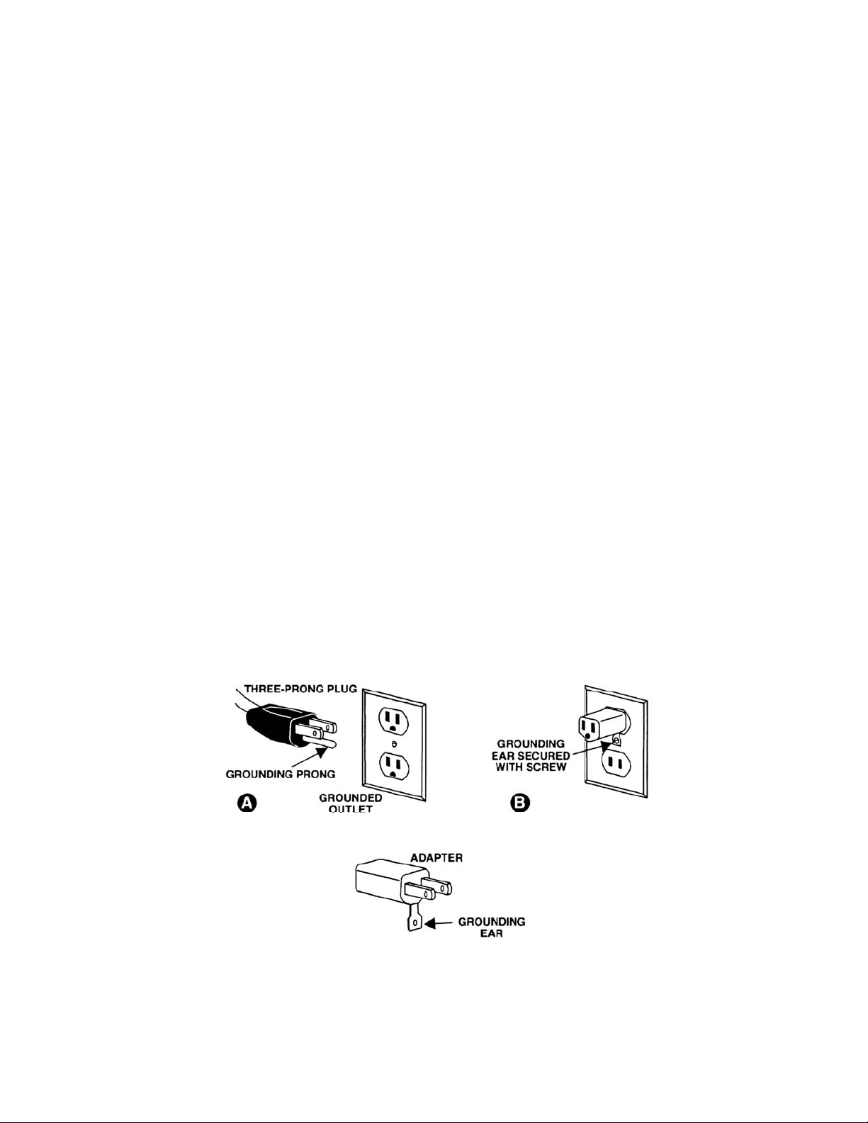
115 Volt Operation
As received from the factory, your sander is ready t o r un at 115 volt operat ion. This sander, w hen wired
for 115 volt, is intended for use on a circuit that has an outlet and a plug that looks like the one illustrated
in (A). A temporary adapt er, which looks like the adapter as illustrated i n (B), may be used to connect
this plug to a two-pole r ecept ac le, as shown in (B) if a properly grounded outlet is not available. The
temporary adapt er should only be used until a properly grounded outlet can be installed by a qualified
electrician. This ad a p ter is n ot applic a ble in C anad a . The green colored rigid ear, lug, or t ab,
extending fr om the adapter, must be connected to a permane nt ground such as a properly gr ounded
outlet box, as shown in (B).
6
Page 7

Introduction
This manual is provided by Walter Meier (Manufacturing) Inc., covering the safe operation and
maintenance procedures for a JET Model JOVS-10 Oscillating Spindle Sander. This manual contains
instructions on installation, safety precautions, general operating procedures, maintenance instructions
and parts breakdow n. This machi ne has been designed a nd constructed to pr ovide years of t rouble free
operation if used i n accorda nce wit h instr uctio ns set forth i n t his manual. I f there are any questio ns or
comments, please contact either your loc al s uppli er or W alter M eier. Walter Meier c an also be reached at
our web site: www.waltermeier.com.
Specifications
Model Number ........................................................................................................................ JOVS -10
Stock Number .......................................................................................................................... 708411
Table Size (in.) ..........................................................................................................................24 x 24
Table Tilt (deg. ) ....................................................................................................................... 45 down
Dust Port Diameter (in.)....................................................................................................................... 4
Spindle Speed (RPM) .................................................................................................................. 1,725
Os c illatio ns pe r Minut e ...................................................................................................................... 75
Length of O s c illa tion (in.) ............................................................................................................... 1-1/2
Worm Gear Environment ............................................................................................................ oil bath
Motor ....................................................................................... TEFC, 1HP, 1Ph, 115V Only, 10A, 60Hz
Control Switch ..................................................................................................... Industrial Push Button
Overall Dimensions (L x W x H)(in.) .................................................................................... 26 x 26 x 42
Net Weight, approximate (lbs. ) ......................................................................................................... 298
The above specificati ons were current at the time t his manual w as publis hed, but beca use of our policy of
continuo us impro vement, Walt er M eier r eser ves the right to change s pecificat ions at any time and without
prior notice, without incurring obligations.
7
Page 8

Unpacking
Contents of the Shipping Container
1 Sander
3 Table Insert Rings
2 Spindle Wrenches
1 2mm Hex Wrench
10 Removable Spindles
1/4” x 6” Steel and Sanding Sleeve
3/8” x 6” Steel and Sanding Sleeve
1/2” x 6” Steel and Sanding Sleeve
5/8” x 6” Steel and Sanding Sleeve
3/4” x 9” Steel and Sanding Sleeve
1” x 9” Rubber and Sanding Sleeve
1-1/2” x 9” Rubber and Sanding Sleeve
2” x 9” Rubber and Sanding Sleeve
3” x 9” Rubber and Sanding Sleeve
4” x 9” Rubber and Sanding Sleeve
1 Owner's Manual
1 Warranty Card
T ools Req uired fo r Assembly and
Adjustments
1 26mm Wrench or Large Adjustable Wrenc h
1 6mm Hex Wrench
1 Square
Read and understand the
entire contents of this manual before
attempting assembly or operation of the
sander. Fai lure t o comply may cause serious
injury.
1. Remove all contents from shipping carton.
2. Report any damage t o your distr ibutor.
3. Do not discard any shipping material until
the sander has been assembled and is
running properly.
4. With help from another person move the
sander off the pallet and into the desired
position.
5. Remove the protect ive coating fo und on the
table using a sof t rag and a cleani ng solvent
that will not damage painted surfaces .
Note: Now is a perfect time to set your sander
up on a m obile base. It w ill make life eas ier in
the woodshop. A JET Heavy Duty Universal
Mobile Base is avail able to f it t his sa nder. JET
also has a variety of Dust Collectors and Air
Filtration Units that will work nicely with your
new sander. Visit waltermeier.com or contact
your JET distributor for options.
8
Page 9

M ou nting S and ing Sleeves
1. Thoro ughly clean the arbors (A, Figure 1) o n
all of the spindle assemblies. Also clean the
arbor housing on the sander.
2. Slip the sanding sleeve (B, Figure 1) over
the spindle and hold in place by tightening
the set screw (C, Fig ure 1) with the supplie d
2mm he x wre nch.
3. Repeat for all of the steel spindle
assemblies.
4. To protect the sanding assemblies, place
them in the holders found on the sides of
the sander. See Figure 2.
Installing Sanding Assemblies
Disconnect the sander from
the power source when installing or
removing sanding assemblies. Failure to
comply may cause serious injur y.
1. Thoroughly clean the arbor and arbor
housing before installing the sanding
assemblies.
2. Thread t he arbor (A, Fig ure 3) into the arbor
housi ng ( B , F ig ure 3) .
3. Use the provided wrenches to hold the
lower ar bor housing nut (C, Fig ure 3) w hile
turning the arbor nut (D, Figure 3)
clockwise.
Figure 1
Figure 2
Removi n g Sand ing Assembl ies
1. Disconnect the sander from the power
source, unplug.
2. Use the provided wrenches to hold the
upper arbor housing nut (E, Figur e 3) while
turning the arbor nut (D, Figure 3) co unter-
clockwise.
Figure 3
9
Page 10

Tab le Insert
1. Disconnect the sander from the power
source, unplug.
2. Choose the insert (A, Figure 4) that most
closely matches the diameter of t he s anding
drum.
3. Line up the notch in the insert with the
spring pin in the table (B, Figure 4), and
press in place.
4. Remove the insert by pressing up from
underneath. Note: Keep t he ope ning in the
table clean so t hat t he insert ca n be easily
put in place, and removed.
Sanding Assembly 90° to Table
1. Loosen the lock k nobs ( C, Figure 5) on the
trunnions and position the table so that it
rests against the 90° stop (D, Figure 6).
Tighten lock knobs.
Figure 4
2. Place a square (E, Figure 5) o n the working
side of the table, and make s ure the sanding
drum is perpendicular t o t he table.
3. If an adjustment needs to be made loosen
the hex nut (F, Figure 6).
4. Loosen lock knobs.
5. Rotate the 90° stop in the appropriate
direction until the table rests 90° to the
sanding drum.
6. Tighten the hex nut while holding the stop.
7. Adjust pointer (G, Figure 6) so that it
indicates the “0” positio n on the scale.
Figure 5
Figure 6
10
Page 11

Repl aci ng San ding Sleeve
1. Loosen hex nut (A, Figure 7) with a 26m m
wrench, or large adjustable wr ench.
2. Slide the sanding sleeve (B, Figure 7) off
the drum and replace with a new sanding
sleeve. Note: If the sanding sleeve is not
easily remo ved, cut the slee ve off and clean
the drum before reinstalling a new slee ve.
3. If you are replacing the sanding sleeves on
the steel spindles, loosen the set screw
found on the arbor nut.
4. Remove sanding sleeve from the spindle
and replace with a new sanding sleeve.
Note: If the sanding sleeve is not easily
removed, cut the sleeve off and clean the
drum before r einstalling a new sleeve.
5. Tighten the set screw.
Dust Collection
In order to collect wood dust, attach a dust
collection hose to the d ust port. A variety of JET
dust collectors, air filtration units, hoses and
adaptors, etc. are available that will work
ef f ect ive ly wi th y o ur new sa nd er . C ont act y our
local JET Distributor for more information.
Maintenance
The ma nufact urer rec om me nds r eplacing the 90
SAE gear lube at 800 hours of use.
1. Open the door on the back side of the
machine to acces s the drain plug (C, Figure
8). Use a 6mm hex wrenc h t o remove the
drain plug.
Figure 7
Figure 8
2. Refill oil through the oil cap (D, Figure 9).
The oil capacity is two quarts.
3. The oil sight glass (E, Figure 8) should read
between the “high” and “low” marks .
Keep the machine and all attachme nts clea n.
All bearings are permanently lubricated and
require no further service.
Figure 9
11
Page 12

Troubleshooting
Trouble Probable Cause Remedy
Sander unplugged from wall or motor . C heck all plug connections.
Sa nder will not sta r t.
Sanding drum does
not come up to
speed.
Machine vibrates
excessively.
Sanded edge not
square.
Sanding marks on
wood.
Fuse blown, or circuit breaker tripped
in service panel.
Cord damaged. Replace cord.
Start ing capacitor bad. Replace starting capacitor .
Extension cord t oo light or too long.
Low current. Contact a qualified elect r icia n.
Stand or base on uneven surface.
Table not square to sanding drum.
Wrong grit sanding sleeve.
Feed pressure too great . Never forc e workpiece.
Replace fuse, or r eset circuit breaker .
Replace wit h adequate size and
length cord.
Adjust stand or base so that it rests
eve nly on the floor.
Use a square to adjust table to
sanding drum.
Use coarser gr it for stock r emoval and
fine grit for finis h sanding.
Replacement Parts
Replacement part s ar e listed on t he fol low i ng pages. To order part s or r eac h our service department, call
1-800-274-6848, Monday through Friday (see our website for business ho urs, www.waltermeier.com).
Having the Model Numb er and Serial Number of your machine availab le when you c all will allow us t o
serve you quickly and accurately.
12
Page 13

Breakdown for the JOVS-10 Oscillating Spindle Sander
13
Page 14

Parts List for the JOVS-10 Oscillating Spindle Sander
Index No. Par t No. Description Size Qty
7 .............. OVS10-007 .............Power Cord ........................................................................................ 1
11 ............ KEY5525.................Key .................................................................................................... 1
18 ............ OVS10-18 ...............Oil Indicator ........................................................................................ 1
20 ............ OS-30628................Oil Seal .............................................................................................. 1
21 ............ BB-6206ZZ ..............Ball Bearing......................................................6206ZZ ...................... 1
22 ............ OVS10 -02 2 .............C-Rin g .............................................................R A6 3 ......................... 1
22A.......... OV S10-022A ...........C-R in g .............................................................RA 62 ......................... 1
26 ............ OVS1 0 -0 2 6 .............Sleeve ............................................................................................... 1
27 ............ OVS10-027 .............Guide Ra il Shaft ................................................................................. 1
28 ............ BB-6205ZZ ..............Ball Bearing......................................................6205LU ...................... 2
29 ............ OVS10-029 .............Locking Nut ........................................................................................ 1
30 ............ OVS10-030 .............Worm ................................................................................................. 1
31 ............ OVS10 -03 1 .............Sprin g Pin ........................................................5x 3 0 mm ............. ....... 1
32 ............ OVS10-032 .............Main Shaft.......................................................................................... 1
33 ............ KEY5550.................Key ..................................................................5x5x50 mm ................ 1
34 ............ OVS1 0 -0 3 4 .............Set Sc re w ........................................................M3x1 2........................ 2
35 ............ OVS10 -03 5 .............Spur Gear .......................................................................................... 1
36 ............ OVS10-036 .............Brass Bu shin g .................................................................................... 2
37 ............ TS-0208061 ............Socket Head Cap Screw ...................................5/16”-18x1”............... 16
38 ............ OVS10-038 .............Transmission Rod Shaft ...................................................................... 2
39 ............ OVS10-039 .............Transmission Rod ............................................................................... 2
40 ............ TS-0640091 ............Hex Nut, Nylon Lock .........................................3/8”-16 ....................... 4
47 ............ OVS10-047 .............Switch Cord........................................................................................ 1
52 ............ OVS10-052 .............Locking Nut ......................................................5/8”-11 ....................... 1
55 ............ OVS10-055 .............Rear Trunnion Bracket ........................................................................ 2
56 ............ TS-0208082 ............Socket Head Cap Screw ...................................5/16”-24x1-1/2” ......... 10
64 ............ OVS10-064 .............Oil Lid ................................................................................................ 1
66 ............ OVS10-066 .............Hex Socket Cap Screw .....................................3/8”-16x3/4”................ 4
67 ............ TS-0680042 ............Flat Washer......................................................3/8” ............................ 8
86 ............ OVS10-086 .............Angle Pointer...................................................................................... 1
87 ............ OVS10-087 .............Pan H ead M achi ne Screw .................................10-24x1/4”.................. 1
88 ............ OVS1 0 -0 8 8 .............Cap ................................................................................................... 1
89 ............ OVS1 0 -0 8 9 .............Nut ..................................................................15/16 ”- 2 4 R.H ..... ........ 2
134 .......... JOVS10-134............Oil Plug ............................................................PT1/4”........................ 1
135 .......... JOVS10-135............Brass Bushing Bracket ........................................................................ 1
136 .......... JOVS10-136............Shaft Brass Bushing ........................................................................... 4
137 .......... JOVS10-137............Knob ................................................................5/16”-18x3/4” .............. 1
139 .......... JOVS10-139W.........Bracket Base ...................................................................................... 2
140 .......... TS-0680032 ............Flat Washer......................................................5/16” ........................ 24
141 .......... TS-0051021 ............Cap Screw .......................................................5/16”-18x5/8” .............. 6
142 .......... JOVS10-142............Swi tc h B ox ......................................................................................... 1
143 .......... JOVS10-143............Pan Head Machine Screw .................................3/16”-24x1-1/2” ........... 2
143A ........ JOVS1 0 -143A .........Hex Nut............................................................3/16”-24 ..................... 2
144 .......... JOVS10-144W.........Vent Cover ......................................................................................... 1
145 .......... JOVS10-145W.........Base .................................................................................................. 1
146 .......... JOVS10-146............Motor Brac k et ..................................................................................... 1
147 .......... JOVS10-147............Motor ........................................................................................ ......... 1
................ JOVS10-147MF .......Motor Fan (not show n) ........................................................................ 1
................ JOVS10-147MFC ....Motor Fan Cover (not shown) .............................................................. 1
................ JOVS10-147CC .......Capacitor Cover (not shown) ............................................................... 1
................ JOVS10-147RC .......Running Capacitor ( not shown) ..........................45uf, 250V ................. 1
................ JOVS10-147SC .......Starting Capac itor ( not shown)...........................300M FD, 125VAC ....... 1
148 .......... JOVS10-148............Strain Relief Bushing .......................................................................... 1
149 .......... TS-0720081 ............Lock Washer ....................................................5/16” ........................ 20
151 .......... JOVS10-151............Coupling He a d.................................................................................... 1
152 .......... JOVS10-152............Ta nk .................................................................................................. 1
153 .......... TS-0267041 ............Set Screw ........................................................1/4”-20x3/8”................ 2
14
Page 15

Index No. Par t No. Description Size Qty
154 .......... JOVS10-154............Ta nk Lid ............................................................................................. 1
155 .......... JOVS10-155............Switch Push Button ............................................................................. 1
156 .......... JOVS10-156W.........Sanding Assembly Rack ..................................................................... 2
158 .......... JOVS10-158W.........Rear Trunnion .................................................................................... 2
159 .......... JOVS10-159............Loc k ing Knob ...................................................3/8 ”-1 6 x3/4”................ 2
160 .......... JOVS10-160W.........Dust Cover ......................................................................................... 1
161 .......... TS-0051061 ............Hex Bolt ...........................................................5/16”-18x1-1/4” ........... 2
162 .......... TS-0561021 ............Hex Nut............................................................5/16”-18 ..................... 6
163 .......... JOVS10-163W.........Working Table .................................................................................... 1
164 .......... JOVS10-164............Sc a l e ........................................................................................ ......... 1
169 .......... JOVS10-169............Fixed Rod .......................................................................................... 1
170 .......... TS-0561031 ............Hex Nut............................................................3/8”-16 ....................... 2
171 .......... JOVS10-171............Ru bber Feet ....................................................................................... 4
172 .......... JOVS10-172............Sinking Head Screw..........................................5/16”-18x3/4” .............. 4
174 .......... JOVS10-174............JE T Logo ........................................................................................... 1
177 .......... JOVS10-177............Pan Head Screw...............................................3/16”-24x3/8” .............. 2
178 .......... JOVS10-178............Swi tc h ................................................................................................ 1
179 .......... JOVS10-179............Sp ring Pin ........................................................3 x22 mm .................... 1
180 .......... JOVS10-180............Fi b e r Was her....................................................3/8” ............................ 2
181 .......... TS-0720091 ............Lock Washer ....................................................3/8” ............................ 4
182 .......... TS-0271071 ............Set Screw ........................................................3/8”-16x3/4”................ 1
183 .......... JOVS10-183............Warning Label .................................................................................... 1
184 .......... JOVS10-184............I.D Label ............................................................................................ 1
185 .......... JOVS1 0 - 1 8 5............Moto r Label ........................................................................................ 1
186 .......... JOVS10-186............Rivet ........................................................................................ .......... 4
187 .......... TS-0267041 ............Set Screw ........................................................1/4”-20x3/8”................ 1
188 .......... JOVS10-188............Sta r Washer .....................................................3/16” .......................... 2
189 .......... TS-0680011 ............Flat Washer......................................................3/16” .......................... 1
190 .......... TS-0267021 ............Set Screw ........................................................1/4”-20x1/4”................ 4
15
Page 16

Sanding Assemblies
16
Page 17

Parts L ist for Sanding Assemblies
Index No. Par t No. Description Size Qty
93................OVS10-093 ................. Wrench ........................................................................ ........................................ 2
94................OVS10-094A .............. Arbor ............................................................................ 3/4” ................................. 6
95................OVS10-095 ................. Hex Nut ....................................................................... ........................................ 6
96................OVS10-096 ................. Spring Pin.................................................................... 3.5x25 mm ..................... 3
97................30105000J .................. Spindle Assembly ....................................................... 4” .................................... 1
98................OVS10-098 ................. Washer ........................................................................ 4” .................................... 2
99................OVS10-099 ................. Nut ............................................................................... 3/4”-16” .......................... 6
100 .............575951 ........................ Sanding Sleeve (60 Grit) – 4 pack ............................ 4” x 9” ................................
....................575953 ........................ Sanding Sleeve (100 Grit) – 4 pack .......................... 4” x 9” ................................
....................575954 ........................ Sanding Sleeve (150 Grit) – 4 pack .......................... 4” x 9” ................................
101 .............30105000I................... Spindle Assembly ....................................................... 3” .................................... 1
102 .............575946 ........................ Sanding Sleeve (60 Grit) – 4 pack ............................ 3” x 9” ................................
....................575948 ........................ Sanding Sleeve (100 Grit) – 4 pack .......................... 3” x 9” ................................
....................575949 ........................ Sanding Sleeve (150 Grit) – 4 pack .......................... 3” x 9” ................................
103 .............OVS10-103 ................. Washer ........................................................................ 3” .................................... 2
104 .............30105000H ................. Spindle Assembly ....................................................... 2” .................................... 1
105 .............575936 ........................ Sanding Sleeve (60 Grit) – 4 pack ............................ 2” x 9” ................................
....................575938 ........................ Sanding Sleeve (100 Grit) – 4 pack .......................... 2” x 9’ ................................
....................575939 ........................ Sanding Sleeve (150 Grit) – 4 pack .......................... 2” x 9” ................................
106 .............OVS10-106 ................. Washer ........................................................................ 2” .................................... 2
107 .............30105000G ................. Spindle Assembly ....................................................... 1-1/2” .............................. 1
108 .............575926 ........................ Sanding Sleeve (60 Grit) – 4 pack ............................ 1-1/2” x 9” .........................
....................575928 ........................ Sanding Sleeve (100 Grit) – 4 pack .......................... 1-1/2” x 9” .........................
....................575929 ........................ Sanding Sleeve (150 Grit) – 4 pack .......................... 1-1/2” x 9” .........................
109 .............OVS10-109 ................. Washer ........................................................................ 1-1/2” .............................. 2
110 .............30105000F ................. Spindle Assembly ....................................................... 1” .................................... 1
111 .............575916 ........................ Sanding Sleeve (60 Grit) – 4 pack ............................ 1” x 9” ................................
....................575918 ........................ Sanding Sleeve (100 Grit) – 4 pack .......................... 1” x 9” ................................
....................575919 ........................ Sanding Sleeve (150 Grit) – 4 pack .......................... 1” x 9” ................................
112 .............OVS10-112 ................. Washer ........................................................................ 1” .................................... 2
113 .............575911 ........................ Sanding Sleeve (60 Grit) – 4 pack ............................ 3/4” x 9” .............................
....................575913 ........................ Sanding Sleeve (100 Grit) – 4 pack .......................... 3/4” x 9” .............................
....................575914 ........................ Sanding Sleeve (150 Grit) – 4 pack .......................... 3/4” x 9” .............................
114 .............OVS10-114A .............. Arbor ............................................................................ 5/8” ................................. 1
115 .............OVS10-115 ................. H ex Nut ....................................................................... 5/8” ................................. 1
118 .............575906 ........................ Sanding Sleeve (60 Grit) – 4 pack ............................ 5/8” x 6” .............................
....................575908 ........................ Sanding Sleeve (100 Grit) – 4 pack .......................... 5/8” x 6” .............................
....................575909 ........................ Sanding Sleeve (150 Grit) – 4 pack .......................... 5/8” x 6” .............................
119 .............OVS10-119A .............. Arbor ............................................................................ 1/2” ................................. 1
120 .............OVS10-120 ................. H ex Nut ....................................................................... 1/2” ................................. 1
122 .............575901 ........................ Sanding Sleeve (60 Grit) – 4 pack ............................ 1/2” x 6” .............................
....................575903 ........................ Sanding Sleeve (100 Grit) – 4 pack .......................... 1/2” x 6” .............................
....................575904 ........................ Sanding Sleeve (150 Grit) – 4 pack .......................... 1/2” x 6” .............................
124 .............OVS10-124A .............. Arbor ............................................................................ 3/8” ................................. 1
125 .............OVS10-125 ................. H ex Nut ....................................................................... 3/8” ................................. 1
127 .............575896 ........................ Sanding Sleeve (60 Grit) – 4 pack ............................ 3/8” x 6” .............................
....................575898 ........................ Sanding Sleeve (100 Grit) – 4 pack .......................... 3/8” x 6” .............................
....................575899 ........................ Sanding Sleeve (150 Grit) – 4 pack .......................... 3/8” x 6” .............................
128 .............OVS10-117 ................. Set Screw .................................................................... 3/16”-24x1/4” ................. 4
129 .............OVS10-129 ................. Arbor ............................................................................ ........................................ 1
130 .............575891 ........................ Sanding Sleeve (60 Grit) – 4 pack ............................ 1/4” x 6” .............................
....................575893 ........................ Sanding Sleeve (100 Grit) – 4 pack .......................... 1/4” x 6” .............................
....................575894 ........................ Sanding Sleeve (150 Grit) – 4 pack .......................... 1/4” x 6” .............................
133 .............OVS10-133A .............. Spindle......................................................................... ........................................ 1
165 .............JOVS10-165 ............... Table Insert (Medium) ................................................ ........................................ 1
166 .............JOVS10-166 ............... Table Insert (Small) .................................................... ........................................ 1
167 .............JOVS10-167 ............... Table Insert (Large) .................................................... ........................................ 1
191 .............JOVS10-191 ............... Spring Pin.................................................................... 5x25 mm ........................ 6
192 .............JOVS10-192 ............... Spring Pin.................................................................... 3x25 mm ........................ 1
17
Page 18

Electrical Connections
18
Page 19

19
Page 20

WALTER MEIER (Manuf acturing) Inc.
427 New Sanford Road
LaVergne, Tennessee 37086
Phone: 800-274-6848
www.waltermeier.com
20
 Loading...