


Operating Instructions and Parts Manual
This .pdf document is bookmarked
Sliding Dual-Bevel Compound Miter Saw
Model JMS-10X and JMS-12X
JET
427 New Sanford Road
LaVergne, Tennessee 37086 Part No. M-707210
Ph.: 800-274-6848 Edition 1 06/2019
www.jettools.com Copyright © 2019 JET
1

1.0 IMPORTANT SAFETY
INSTRUCTIONS
WARNING – To reduce risk of injury:
1.1 General machine safety warnings
1. Read and understand the entire owner's
manual before attempting assembly or
operation.
2. Read and understand the warnings posted on
the machine and in this manual. Failure to
comply with all of these warnings may cause
serious injury.
3. Replace warning labels if they become
obscured or removed.
4. This saw is designed and intended for use by
properly trained and experienced personnel
only. If you are not familiar with the proper and
safe operation of a miter saw, do not use until
proper training and knowledge have been
obtained.
5. Do not use this saw for other than its intended
use. If used for other purposes, JET disclaims
any real or implied warranty and holds itself
harmless from any injury that may result from
that use.
6. Always wear approved safety glasses or face
shield while using this saw. Everyday
eyeglasses only have impact resistant lenses;
they are not safety glasses.
7. Before operating this saw, remove tie, rings,
watches and other jewelry, and roll sleeves up
past the elbows. Do not wear loose clothing.
Confine long hair. Non-slip footwear or anti-skid
floor strips are recommended. Do not wear
gloves.
8. Wear ear protectors (plugs or muffs) during
extended periods of operation.
9. Make certain the switch is in the OFF position
before connecting the machine to the power
supply.
10. Make certain the machine is properly grounded.
11. Make all machine adjustments or maintenance
with the machine unplugged from the power
source.
12. Remove adjusting keys and wrenches. Form a
habit of checking to see that keys and adjusting
wrenches are removed from the machine
before turning it on.
13. Keep safety guards in place at all times when
the machine is in use. If removed for
maintenance purposes, use extreme caution
and replace the guards immediately after
completion of maintenance.
14. Check damaged parts. Before further use of the
machine, a guard or other part that is damaged
should be carefully checked to determine that it
will operate properly and perform its intended
function. Check for alignment of moving parts,
binding of moving parts, breakage of parts,
mounting and any other conditions that may
affect its operation. A guard or other part that is
damaged should be properly repaired or
replaced.
15. Provide for adequate space surrounding work
area and non-glare, overhead lighting.
16. Keep the floor around the machine clean and
free of scrap material, oil and grease.
17. Keep visitors a safe distance from the work
area. Keep children away.
18. Make your workshop child proof with padlocks
or master switches.
19. Give your work undivided attention. Looking
around, carrying on a conversation and “horseplay” are careless acts that can result in serious
injury.
20. Maintain a balanced stance at all times so that
you do not fall into the blade or other moving
parts. Do not overreach or use excessive force
to perform any machine operation.
21. Use the right tool at the correct speed and feed
rate. Do not force a tool or attachment to do a
job for which it was not designed. The right tool
will do the job better and more safely.
22. Use recommended accessories; improper
accessories may be hazardous.
23. Maintain tools with care. Keep saw blades
sharp and clean for the best and safest
performance. Follow instructions for lubricating
and changing accessories.
24. Always disconnect power to the machine
(unplug) before performing maintenance.
25. Use a brush or compressed air to remove chips
or debris — do not use bare hands.
26. Do not stand on the machine. Serious injury
could occur if the machine tips over.
27. Never leave the machine running unattended.
Turn the power off and do not leave the
machine until it comes to a complete stop.
28. Remove loose items and unnecessary work
pieces from the area before starting the
machine.
2

29. Keep hands out of the line of saw blade.
30. Don’t use in dangerous environment. Don’t use
power tools in damp or wet location, or expose
them to rain. Keep work area well lighted.
1.2 Miter saw safety warnings
Specific safety instructions for this compound miter
saw:
31. Do not operate the miter saw until it is
completely assembled and installed according
to these instructions.
32. If you are not familiar with the operation of miter
saws, seek guidance from your supervisor,
instructor or other qualified person.
33. Always hold the work firmly against the fence
and table.
34. Do not perform free-hand operations; use
clamp wherever possible.
35. Keep hands out of the path of the saw blade. If
the workpiece you are cutting would cause your
hands to be within 8 inches of the saw blade,
the workpiece should be clamped in place
before making the cut.
36. Be sure the blade is sharp, runs freely and is
free of vibration.
37. Allow the motor to come up to full speed before
starting a cut.
38. Keep the motor air vents clean and free of chips
or dust.
39. Make sure all handles are tight before cutting,
even if table is positioned in one of the positive
stops.
40. Be sure both the blade and the flange are clean
and the arbor bolt is tightened securely.
41. Use only blade flanges specified for your saw.
42. Never use blades larger in diameter than the
size specified by your particular model.
43. Never apply lubricants to the blade when it is
running.
44. Always check the blade for cracks or damage
before operation. Replace a cracked or
damaged blade immediately.
45. Never use blades rated for fewer RPM’s than
the rated speed of the saw. See your saw
specifications.
46. Always keep blade guards in place and use at
all times.
47. Never reach around the saw blade.
48. Make sure the blade is not contacting the
workpiece before the switch is turned ON.
49. After completing the cut, release the trigger and
wait for the blade to stop before returning the
saw to raised position.
50. Make sure the blade has come to a complete
stop before removing or securing the
workpiece, changing the workpiece angle or
changing the angle of the blade.
51. Never cut metals or masonry products with this
tool. This miter saw is designed for use on wood
and wood-like products.
52. Never cut small pieces. If the workpiece being
cut would cause your hand or fingers to be
within 8 inches of the saw blade, the workpiece
is too small.
53. Provide adequate support to the sides of the
saw table for long work pieces.
54. Never use the miter saw in an area with
flammable liquids or gases.
55. Never use solvents to clean plastic parts.
Solvents could possibly dissolve or otherwise
damage the material.
56. Shut off the power before servicing or adjusting
the tool.
57. Disconnect the saw from the power source and
clean the machine when finished using.
58. Make sure the work area is clean before leaving
the machine.
59. Should any part of your miter saw be missing,
damaged, or fail in any way, or any electrical
component fail to perform properly, remove the
plug from the power supply outlet. Replace
missing, damaged, or failed parts before
resuming operation.
WARNING: This product can expose you to
chemicals including lead and cadmium which
are known to the State of California to cause
cancer and birth defects or other reproductive
harm, and phthalates which are known to the
State of California to cause birth defects or other
reproductive harm. For more information go to
http://www.p65warnings.ca.gov.
WARNING: Drilling, sawing, sanding or
machining wood products generates wood dust
and other substances known to the State of
California to cause cancer. Avoid inhaling dust
generated from wood products or use a dust
mask or other safeguards for personal
protection.
Wood products emit chemicals known to the
State of California to cause birth defects or other
reproductive harm. For more information go to
http://www.p65warnings.ca.gov/wood.
3

Familiarize yourself with the following safety notices used in this manual:
This means that if precautions are not heeded, it may result in minor injury and/or possible
machine damage.
This means that if precautions are not heeded, it may result in serious, or possibly even fatal,
injury.
2.0 Table of contents
Section Page
1.0 IMPORTANT SAFETY INSTRUCTIONS ....................................................................................................... 2
1.1 General machine safety warnings .............................................................................................................. 2
1.2 Miter saw safety warnings .......................................................................................................................... 3
2.0 Table of contents ............................................................................................................................................ 4
3.0 About this manual .......................................................................................................................................... 6
4.0 Features and terminology .............................................................................................................................. 7
5.0 Specifications ................................................................................................................................................. 8
5.1 Cutting capacities ....................................................................................................................................... 9
6.0 Setup and assembly ..................................................................................................................................... 10
6.1 Unpacking ................................................................................................................................................ 10
6.2 Shipping contents ..................................................................................................................................... 10
6.3 Tools required for assembly ..................................................................................................................... 10
6.4 Transporting the saw ................................................................................................................................ 10
6.5 Mounting saw to bench ............................................................................................................................ 10
6.6 Releasing slide carriage ........................................................................................................................... 10
6.7 Releasing cutting head ............................................................................................................................. 10
6.8 Dust extraction ......................................................................................................................................... 10
6.9 Power cord storage clips .......................................................................................................................... 11
6.10 Saw blade wrench .................................................................................................................................. 11
6.11 Installing hold-down ................................................................................................................................ 11
6.12 Removing/installing blade ...................................................................................................................... 11
7.0 Electrical connections .................................................................................................................................. 12
7.1 Extension cords ........................................................................................................................................ 12
8.0 Adjustments ................................................................................................................................................. 13
8.1 Support foot .............................................................................................................................................. 13
8.2 Miter angle setting .................................................................................................................................... 13
8.3 Table extensions and work stop ............................................................................................................... 13
8.4 Fence adjustment ..................................................................................................................................... 14
8.5 Bevel adjustments .................................................................................................................................... 14
8.6 Depth adjustment ..................................................................................................................................... 15
9.0 Operation ..................................................................................................................................................... 15
9.1 LED light ................................................................................................................................................... 15
9.2 Laser guide ............................................................................................................................................... 15
9.3 General saw operation ............................................................................................................................. 16
9.4 Jammed material ...................................................................................................................................... 16
9.5 Cutting options ......................................................................................................................................... 16
9.6 Cutting bowed material ............................................................................................................................. 17
9.7 Rough cutting a dado ............................................................................................................................... 17
9.8 Base molding ............................................................................................................................................ 17
9.9 Crown molding ......................................................................................................................................... 17
10.0 User-maintenance ...................................................................................................................................... 17
10.1 General cleaning .................................................................................................................................... 17
10.2 Lower Blade Guard ................................................................................................................................ 18
10.3 Lubrication .............................................................................................................................................. 18
10.4 Commutator brush inspection ................................................................................................................ 18
10.5 Additional servicing ................................................................................................................................ 18
11.0 Crown molding charts ................................................................................................................................ 19
4

11.1 Crown molding: 90° wall angles ............................................................................................................. 19
11.2 Crown molding: various wall angles ....................................................................................................... 20
12.0 Troubleshooting JMS-10X,12X Miter Saws ............................................................................................... 21
13.0 Replacement Parts ..................................................................................................................................... 22
13.1.1 JMS-10X (#707210) – Miter Saw Assembly – Exploded View I ......................................................... 23
13.1.2
13.1.3 JMS-10X (#707210) – Miter Saw Assembly – Parts List .................................................................... 25
13.2.1 JMS-12X (#707212) – Miter Saw Assembly – Exploded View I ......................................................... 29
13.2.2 JMS-12X (#707212) – Miter Saw Assembly – Exploded View II ......................................................... 30
13.2.3 JMS-12X (#707212) – Miter Saw Assembly – Parts List ..................................................................... 31
14.0 Electrical Connections – JMS-10X,12X ..................................................................................................... 35
15.0 Warranty and service ................................................................................................................................. 36
JMS-10X (#707210) – Miter Saw Assembly
– Exploded View II
......................................................... 24
5

3.0 About this manual
This manual is provided by JET, covering the safe operation and maintenance procedures for a JET Model JMS10X and JMS-12X Miter Saw. This manual contains instructions on installation, safety precautions, general
operating procedures, maintenance instructions and parts breakdown. Your machine has been designed and
constructed to provide consistent, long-term operation if used in accordance with the instructions set forth in this
document.
If there are questions or comments, please contact your local supplier or JET. JET can also be reached at our
web site: www.jettools.com.
Retain this manual for future reference. If the machine transfers ownership, the manual should accompany it.
Read and understand the entire contents of this manual before attempting assembly or
operation. Failure to comply may cause serious injury.
Register your product using the provided mail-in card, or register online: http://www.jettools.com/us/en/serviceand-support/warranty/registration/
6

4.0 Features and terminology
Figure 4-1: Features and Terminology
7

5.0 Specifications
Table 1
Model number
Stock number 707210 707212
Motor and Electricals
Motor type Series-wound, double insulated
Input power 1.7 kW
Phase single
Voltage 115 V
Cycle 60 Hz
Listed FLA (full load amps) 15 A
Motor speed 4000±10% RPM
Starting amps 25 A
Running amps (no load) 5.10 A 5.33±10% A
Switch Saw: 18A,127V; Laser: 6A 250AC; LED: 10A 125VAC
Power cable SJT 14AWGx3C, 8-1/2 ft.
Power plug Type ZT-1 (115V), without ground
Recommended circuit size 1 15 A
Sound emission 2 95 dB at 3 ft. (900mm) from blade
Laser Class 2, 3V 400~700 NM
Work light LED
Capacities and measurements
Blade speed 4000±10% RPM
Motor arbor size Ø 5/8 in. (15.875 mm)
Reducer for blade to arbor n/a
Ø10in. x 40T x 5/8in. arbor,
Saw blade
Blade arbor size 5/8 in. (15.875 mm) 1 in. (25.4 mm)
Miter cutting range 52° Left, 60° Right
Bevel cutting range 0° to 45° L & R
Miter stops 0, 15, 22.5, 31.6, 45 deg. L & R and 60 deg. R
Bevel stops 45° L, 0°, 45° R
Maximum sliding travel 9-3/8 in. (240 mm) 9.2 in. (233 mm)
Cutting capacity
Dust collection
Dust port diameter Ø 1-5/8 in. (40.6 mm)
Adaptor diameters Ø 1-5/8 in. (40.6 mm) to 2-1/2 in. (63 mm)
Main materials
Work table Aluminum
Base Aluminum
Extension support Aluminum
Upper blade guard Aluminum
Lower blade guard PC
Slide bar Steel
Upper sliding fence Aluminum
Lower fixed fence Aluminum
Dimensions
Machine overall dimensions, LxWxH
Shipping dimensions, LxWxH
carbide tipped, (Ø254 x 15.875 x
2.8mm – 40T); Nmax. 7000 RPM
43-1/2 x 29-1/2 x 28-1/2 in.
37-3/8 x 24-7/8 x 14-1/2 in.
JMS-10X JMS-12X
Ø12in. x 48T x 1in. arbor, carbide
tipped, (Ø305 x 25.4T x 2.8mm –
48T); Nmax. 7000 RPM
See Table 2
47-1/2 x 30 x 30-5/8 in.
(1100 x 750 x 720 mm)
(950 x 630 x 370 mm)
(1200 x 760 x 780 mm)
41-3/4 x 26 x 17-3/8 in.
(1060 x 660 x 440 mm)
Ø 5/8 x 1 x 0.11 in.
(16 x 25.4 x 2.8 mm)
8

Weights
Net weight (approx.) 47 lbs. (21 kg) 56 lbs. (25 kg)
Shipping weight (approx.) 54 lbs. (24 kg) 62 lbs. (28 kg)
5.1 Cutting capacities
Table 2
JMS-10X JMS-12X
Type of cut Miter angle Bevel angle Capacity
Cross cut 0° 0° 12 x 3-9/16 in. (305 x 90 mm) 14 x 4.0 in. (355 x 100 mm)
Miter cut 45° L & R 0° 8-1/2 x 3-9/16 in. (215 x 90 mm) 10 x 4.0 in. (254 x 100 mm)
Bevel cut 0° 45° L 12 x 1-9/16 in. (305 x 40 mm) 14 x 2.0 in. (355 x 50 mm)
Bevel cut 0° 45° R 12 x 1.0 in. (305 x 25 mm) 14 x 1-3/8 in. (355 x 35 mm)
Compound 45° L & R 45° L 8-1/2 x 1-9/16 in. (215 x 40 mm) 10 x 2.0 in. (254 x 50 mm)
Compound
1
subject to local and national electrical codes.
2
The specified values are emission levels and are not necessarily to be seen as safe operating levels. As workplace
45° L & R
conditions vary, this information is intended to allow the user to make a better estimation of the hazards and risks
involved only.
L = length, W = width, H = height
L & R = Left and Right
n/a = not applicable
The specifications in this manual were current at time of publication, but because of our policy of continuous
improvement, JET reserves the right to change specifications at any time and without prior notice, without incurring
obligations.
45° R
8-1/2 x 1.0 in. (215 x 25 mm) 10 x 1-3/8 in. (254 x 35 mm)
9

Read and understand the entire
contents of this manual before attempting
assembly or operation. Failure to comply may
cause serious injury.
Use C-clamps to clamp this mounting board to a
stable work surface at the worksite.
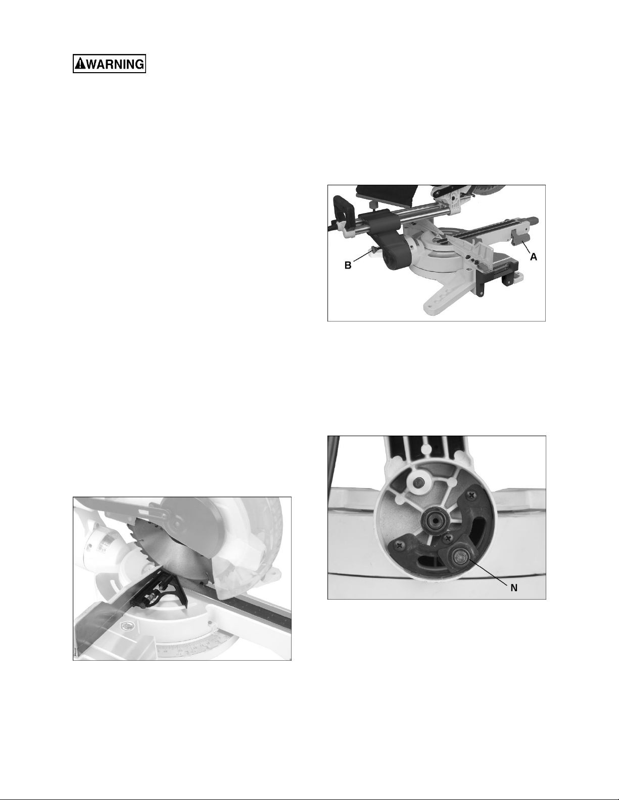
6.6 Releasing slide carriage
Loosen slide locking knob (A, Figure 8-1).
6.0 Setup and assembly
6.1 Unpacking
Inspect contents for shipping damage or missing
parts. If either is discovered, report it to your
distributor.
Do not discard carton or packing material until saw
is assembled and running satisfactorily.
6.2 Shipping contents
1 Miter saw
1 Dust bag
1 Dust port adaptor
1 Hold-down clamp assembly
3 Hex wrenches, 2.5/3/6 mm
(6mm wrench is preinstalled in rear handle)
6.3 Tools required for assembly
Hex wrenches – 2.5mm, 6mm
(Additional tools may be needed for adjustment
procedures and securing the miter saw to a
workbench.)
When transporting or storing
miter saw, the slide carriage should always be
locked in position.
6.7 Releasing cutting head
When not in use, lock cutting
head in down position. Failure to comply can
cause serious injury or equipment damage.
1. Push down on operating handle.
2. Pull out on head release pin (B, Figure 6-1).
3. Raise cutting head to UP position.
Note: When not in use, lock cutting head in down
position:
4. Pull out on head release pin (B) and bring
cutting head down.
5. Push in head release pin (B) to lock.
6.4 Transporting the saw
Observe the following safety measures to avoid
injury from unexpected saw movement:
Disconnect power cord and wrap it around the
storage clips.
Bring cutting head to forward position and
down, and lock it in lower position.
Lock slide carriage in place.
Always use the carrying handles when lifting or
moving to avoid damage to machine.
Bend at the knees, not from the back.
6.5 Mounting saw to bench
For stationary use:
Select a location for the saw, such as the top of a
workbench, that provides sufficient room for
handling workpieces. Secure the saw to the bench.
Mounting hardware is not included and must be
purchased separately.
For portable use:
Place saw on a 3/4-in. thick piece of plywood and
bolt the base securely to the plywood using the
mounting holes on base. Mounting hardware is not
included and must be purchased separately.
Figure 6-1
6.8 Dust extraction
6.8.1 Dust bag
Push dust bag onto exhaust port (Figure 6-1).
To empty dust bag, remove it from exhaust port,
slide off plastic clip (C
sawdust through bag opening. Reinstall clip before
using dust bag.
Note: Inspect and empty bag frequently; do not wait
for it to become full.
, Figure 6-1) and empty
1
10

6.8.2 Adaptor
The adaptor can be used to convert the 1-5/8 in.
diameter port to 2-1/2 in. diameter, for connection to
a hose used with a shop vacuum or other dust
collection system. Use a hose clamp to secure the
dust hose (not provided) to the saw port.
6.9 Power cord storage clips
The slide carriage has two clips for cord storage
when machine is not in use (D, Figure 6-1).
6.10 Saw blade wrench
The hex wrench used for blade changing is stored
in the rear handle (E, Figure 6-1). The hex wrench
also has a cross-point driver on its opposite end.
6.11 Installing hold-down
1. Insert hold-down post (F, Figure 6-2) into
mounting hole located behind left or right fence.
2. Loosen knob (G) to raise or lower clamp
support, then tighten knob.
3. Press button (H) to allow clamp to drop onto
workpiece, then use knob (J) to tighten clamp
against workpiece.
Figure 6-3
5. Allow cover plate and guard to fall backward, to
expose arbor bolt (L, Figure 6-4).
6. Press and hold arbor lock on opposite side of
head (Figure 6-5) while rotating blade until
arbor lock engages.
7. Continue pressing arbor lock, while loosening
arbor bolt with hex wrench. NOTE: Left-hand
threads – turn clockwise to loosen.
Figure 6-2
6.12 Removing/installing blade
Disconnect power (unplug) to
avoid accidental starts. Failure to comply may
cause serious injury.
1. Unplug saw from electrical outlet.
2. Raise cutting head to upright position.
3. Raise lower blade guard to uppermost position
and hold. See Figure 6-3.
4. Loosen cover plate screw (K, Figure 6-3) with
provided crosspoint tool.
Figure 6-4
Figure 6-5
8. Remove arbor bolt, outer flange, and blade. (On
model JMS-12X, also remove reducer sleeve).
See Figure 6-6. Do not remove inner flange.
Note: Pay attention to the pieces removed,
noting their position and direction they face.
Wipe pieces clean of any sawdust before
installing a new blade.
11

Figure 6-6
Important: Make sure blade size and arbor hole
match specification of miter saw.
9. Install new blade. Rotation arrow on blade must
match clockwise rotation arrow on upper guard,
and the blade teeth must point downward.
10. Place flange outer flange against blade and on
arbor. Thread arbor bolt onto arbor in
counterclockwise direction.
Important: Make sure flat edge inside flange
opening is aligned with flat edge on arbor shaft.
Also, the flat -side of the flange must be placed
against blade.
6. Press and hold arbor lock (Figure 6-5) while
rotating blade until arbor lock engages.
7. Tighten arbor bolt.
8. Rotate cover plate back to original position, until
slot in cover plate engages completely with
cover plate screw (K, Figure 6-3). While holding
lower blade guard up as shown in Figure 6-3,
tighten screw.
9. Lower blade guard and verify that it operates
smoothly without binding or sticking.
Never use saw without cover
plate securely in place and screw tightened
down. Failure to comply may cause serious
injury.
If arbor bolt should accidentally loosen, the cover
plate prevents it from falling out, and helps prevent
the spinning blade from coming off the saw.
7.0 Electrical connections
To avoid electrical hazards, fire
hazards, or damage to the machine, use proper
circuit protection. Your saw is wired at the
factory for 115V operation. Connect to a 120V,
15 Amp circuit and use a 15 amp time delay fuse
or circuit breaker. If power cord is worn or cut,
or damaged in any way, have it replaced
immediately to avoid shock or fire.
Before connecting to power source, be sure switch
is in off position.
This machine is double insulated to provide a double
thickness of insulation between the user and the
machine's electrical system. All exposed metal parts
are isolated from the internal metal motor
components with protective insulation.
This saw has a plug that looks like the one shown in
Figure 7-1.
Figure7-1
To reduce the risk of electrical shock, this saw has
a polarized plug (one blade is wider than the other).
This plug will fit in a polarized outlet only one way; if
the plug does not fit fully in the outlet, reverse the
plug. If it still does not fit, contact a qualified
electrician to install the proper outlet. Do not alter
the plug in any way.
Double insulation does not take the place of normal
safety precautions when operating this tool.
To avoid electrocution:
1. Use only identical replacement parts when
servicing a tool with double insulation. Servicing
should be performed by a qualified technician.
2. Do not use power tools in wet or damp locations
or expose them to rain or snow.
Verify that the flanges are clean
and properly installed. Lower the blade into the
table and verify that it does not come into
contact with the base, table, or table inserts.
Failure to comply may cause serious injury.
7.1 Extension cords
The use of extension cords is discouraged; try to
position equipment within reach of the power
source. If an extension cord becomes necessary, be
sure it is heavy enough to carry the current your
product will draw. An undersized cord will cause a
drop in line voltage resulting in loss of power and
overheating.
Table 3 shows recommended size to use depending
on cord length and nameplate ampere rating. If in
doubt, use the next heavier gauge. The smaller the
gauge number, the heavier the cord.
12

Cord length Wire gauge (AWG)
0 – 25 ft. 16
25- 50 ft. 14
Table 3
Important: Make certain the receptacle in question
is properly grounded. If you are not sure, have a
registered electrician check the receptacle.
8.0 Adjustments
Note: Your miter saw was adjusted by the
manufacturer. However, during shipment slight
misalignment may have occurred. Check the
following settings and adjust if necessary prior to
using this miter saw.
8.1 Support foot
The foot (A, Figure 8-1) can be turned in or out to
adjust its height. It is designed to provided support
for the miter table when locking handle is pushed
down or when cutting head is brought forward for
slide-cutting. The foot should be adjusted to contact
surface of bench or worktable.
8.2 Miter angle setting
The miter scale shows miter angles from 0° to 52°
to the left, and 0° to 60° to the right.
To set miter angle:
1. Lift up on miter lock handle (B, Figure 8-1) to
unlock table.
2. Press and hold release button (C) and use miter
lock handle to push cutting arm until desired
degree aligns with angle indicator (D).
3. Push down miter lock handle (B) to lock the
position.
Note: The release button (C) can be continuously
engaged to bypass the stops. This is convenient
when frequent and quick adjustment of miter angles
is needed.
1. Push down release button (C) and push in pin
(E). Release button is now continuously
engaged.
2. Grasp handle (B) and freely rotate cutting arm.
3. Press release button (C) again to disengage
pin.
Figure 8-1: selecting miter angles
8.2.1 Miter positive stop selection
The miter saw table has preset stops for quick and
accurate positioning at common angle settings of 0°,
15°, 22.5°, 31.6°, and 45° left and right; and 60°
right.
1. Lift up on miter lock handle (B, Figure 8-1) to
unlock table.
2. Press release button (C) and move table with
handle (B). As scale indicator approaches the
desired degree, release the button (C). The
table will engage the next positive stop.
3. Push down miter lock handle (B) to lock the
position.
8.2.2 Miter scale indicator alignment
1. Rotate table to the 0° stop.
2. If indicator (D, Figure 8-1) does not align with
zero on scale, loosen screw and adjust indicator
to 0° mark. Retighten screw.
8.3 Table extensions and work stop
Pull up lock handle (H, Figure 8-2) and slide table
extension outward, as shown. Push down lock
handle to secure position.
Raise workstop (J) for quick positioning of stock
when cutting multiple pieces of equal length.
13
Figure 8-2
8.4 Fence adjustment
8.5 Bevel adjustments
The fence extensions must be
extended to left or right, or removed entirely, when
making bevel cuts, to prevent blade or guard
obstruction. Failure to comply may cause serious
injury.
Failure to extend the fence will not allow enough
space for the blade to pass through. This could
result in serious injury. At extreme miter or bevel
angles the saw blade may also contact the fence
resulting in damage to equipment as well as
personal injury.
IMPORTANT: Make a “dry run” of the cut, including
downward and sliding paths, and resolve any
potential fence obstructions before turning on the
saw.
To adjust fence:
1. Raise lock handle (F, Figure 8-2) to unlock
fence extension.
2. Slide fence extension (K) outward to
accommodate desired bevel angle, or slide it
completely off.
3. Push down lock handle (F) to tighten fence
extension in position.
Note: Secure fence extensions in position closest to
saw blade when transporting the miter saw.
8.4.1 Checking fence squareness
1. Unplug saw from electrical outlet.
2. Loosen four fence locking screws (G, Figure 8
2). Note: Two locking screws to each fence.
3. Lower cutting head and lock in position.
4. Place a combination square against fence and
blade, as shown in Figure 8-3.
8.5.1 90° (zero) bevel stop adjustment
1. Unplug saw from electrical outlet.
2. Pull up bevel lock handle (A, Figure 8-4) to
unlock tilt mechanism.
3. Pull out on bevel pin (B, Figure 8-4) and tilt
cutting arm to 90° position (0° on bevel scale)
against positive stop.
4. Push down lock handle (A) to secure cutting
head angle.
Figure 8-4
NOTE: If lock handle (A) is disengaged and bevel
pin (B) has been pulled out, but cutting head still
refuses to tilt, the lock nut may have been
overtightened for shipping purposes. Remove three
screws and open rear cover (see Figure 8-5).
Slightly loosen lock nut (N, Figure 8-5) with wrench.
Reinstall rear cover. This adjustment is only if
necessary.
Figure 8-3
5. Adjust fence square to blade and tighten the
four fence locking screws (G, Figure 8-2).
6. After fence has been aligned, use a scrap piece
of wood to make a cut at 90º, then check
squareness of the piece. Readjust if necessary.
Figure 8-5
5. Place a combination square flat on the table
and against blade, as shown in Figure 8-6.
14
Note: Position the square flush against main
blade surface, not against a projecting blade
tooth.

Figure 8-6
6. If blade is not 90° to miter table (i.e. square does
not sit flush against both surfaces), turn right set
screw (E, Figure 8-7) in or out until blade is 90°
to table.
7. If needed, loosen screw (D, Figure 8-7) and
adjust bevel angle indicator to align with zero on
scale. Retighten screw.
8.6 Depth adjustment
Cutting depth can be pre-set for even and repetitive
shallow cuts, such as slots or dadoes.
1. Raise cutting head.
2. Loosen screw (F, Figure 8-8) and slide plate (G)
outward. Retighten screw.
3. Pull cutting head down until blade teeth are at
desired depth of cut.
4. Hold cutting head in this position and turn stop
screw (H) until it touches plate (G).
5. Rotate knurled nut (J) against casting to secure
setting.
6. Recheck blade depth by moving cutting head
front to back through the full motion of a typical
cut along the control arm.
Figure 8-7
8.5.2 45° bevel stop adjustment
1. Unplug saw from electrical outlet.
2. Make sure 90-degree bevel stop is accurate
(sect. 8.5.1).
3. Set miter angle to zero degrees. Fully extend
both sliding fences to prevent obstruction.
4. Pull up bevel lock handle (A, Figure 8-4).
5. Pull out bevel lock pin (B, Figure 8-4) and tilt
cutting head to 45-degrees left. The cutting
head should stop at the 45-degree mark on
scale.
10. If adjustment is needed, turn left set screw (C)
as needed to bring cutting head to 45-degree
mark on scale. Verify the setting using a 45degree angle tool on the table and against
blade.
Note: The left set screw (C, Figure 9-7) may be
used instead to set a different angle stop, less than
45°, that is used frequently by the operator.
The right 45° tilt stop will have already been
established when the 90° setting is calibrated in
sect. 8.5.1.
Figure 8-8
9.0 Operation
Before operating miter saw,
make sure that you have read and thoroughly
understand all safety instructions in sect. 1.0.
Failure to comply may result in serious injury.
Before operating miter saw, verify that blade will
not be obstructed. Remove fence extensions if
needed. Failure to comply may result in serious
injury and/or damage to saw.
Make sure all locking handles function properly.
A malfunctioning locking handle can present a
safety hazard.
9.1 LED light
Use rocker switch atop handle to turn light on and
off. See Figure 4-1.
9.2 Laser guide
Laser radiation. Avoid direct
eye exposure. The use of optical instruments
with this product will increase eye hazard. Refer
to Figure 9-1.
15

Figure 9-1
Use rocker switch atop handle to turn laser guide on
and off (see Figure 4-1). The laser must align with
blade cutting path.
The laser has no user-adjustments. If you suspect
realignment is necessary, take the miter saw to an
approved service center.
9.4 Jammed material
If a jam occurs, release trigger and wait for all
moving parts to stop. Unplug saw and remove
jammed items.
9.5 Cutting options
9.5.1 Chop cuts
For chop cutting operations on small workpieces,
slide cutting head completely toward rear of unit and
tighten slide lock knob (A, Figure 8-1). Follow
general cutting procedures of sect. 9.3.
9.5.2 Sliding cuts
To cut wide boards, loosen slide lock knob (A, Figure
8-1) to allow cutting head to slide freely. See
specifications for maximum slide capacity of your saw.
Do not attempt to repair or
disassemble the laser. If unqualified persons
attempt to repair this laser product, serious
injury may result. Any repair or adjustment
required on this laser product should be
performed by authorized service center
personnel.
9.3 General saw operation
9.3.1 Starting the cut
1. Set desired bevel and/or miter angles and lock
the settings. See sect. 8.2 and 8.5.
2. Place hands a safe distance away from blade
path.
3. Hold workpiece firmly against fence to prevent
it creeping toward blade. Use hold-down clamp
whenever possible.
4. Perform a “dry run” – bring blade down to
workpiece to confirm cutting path of blade, and
ensure that no obstacles are present. If needed,
slide the fence extension(s) away or remove
them entirely.
5. Position blade just above the workpiece. Press
release button on either left or right side of
operating handle, and press trigger (see Figure
4-1) to start saw. Blade must NOT be contacting
workpiece when trigger is pressed.
6. Lower blade into workpiece with a firm
downward motion.
9.3.2 Finishing the cut
7. Hold cutting head in down position.
8. Release trigger and wait for all moving parts to
stop before moving your hands and raising
cutting arm.
Note: The miter saw is equipped with an electrical
blade brake. When trigger is released, the brake will
automatically stop the blade in approximately 3
seconds.
Observe these precautions:
Never pull cutting head assembly and
spinning blade toward you during the cut.
Allow blade to reach full speed before
cutting.
Extend fence by sliding it out to required
location, or
Remove right sliding fence if necessary.
Return carriage to full rear position after
each crosscut operation.
To crosscut boards that are wider than the length of
the saw blade, proceed as follows:
1. Set desired bevel and/or miter angles and lock
the settings. See sect. 8.2 and 8.5.
2. Position workpiece against fence and clamp it
to the table.
3. Loosen slide lock knob (A, Figure 8-1).
4. Grasp operating handle and pull cutting head
forward until center of saw blade is over front of
workpiece.
5. Press release button and trigger to turn on saw.
6. When saw reaches full speed, push handle
down slowly, cutting through leading edge of
workpiece.
7. Slowly push operating handle back toward
fence to complete the cut. Do not use excessive
force; allow blade to do the cutting.
8. Release trigger and allow blade to stop spinning
before allowing cutting head to rise.
9.5.3 Miter cutting
Rotate table to desired miter angle as shown on
miter scale. Refer to sect. 8.2.
The miter setting can be locked down at any angle
from 52° left to 60° right.
16

Miter stops are provided at common angles of 0°,
15°, 22.5°, 31.6°, 45° left and right, and 60° right.
Always push down miter lock handle (B, Figure 8-1)
to secure table in position.
9.5.4 Bevel cutting
Tilt cutting head to desired angle as shown on bevel
scale. Refer to sect. 8.5.1.
The blade can be tilted at any angle, from 90°
straight cut (0° on scale) to 45° left and right bevel.
Always push down bevel lock handle (A, Figure 9-4)
to secure cutting head in position.
Bevel positive stops are provided at 0° and 45° left
and right.
9.5.5 Compound cuts
A compound cut involves both miter and bevel
angles in the same operation.
The charts in sect. 11.0 show miter and bevel
settings for specific angles of compound cuts.
9.6 Cutting bowed material
A curved or warped workpiece must be secured
against the fence and with a clamping device used.
To help prevent binding, place convex side of
workpiece against fence. An extremely warped
piece should not be used.
9.7 Rough cutting a dado
1. Mark lines identifying width and depth of
desired cut on the workpiece and position on
the table so that inside tip of blade is positioned
on the line. Use hold down clamp to secure
workpiece.
2. Set cutting depth as described in sect. 8.6.
3. Cut two parallel grooves, then remove the
material between them.
9.9 Crown molding
Your compound miter saw is suited for the difficult
task of cutting crown molding. To fit properly, crown
molding must be compound-mitered with extreme
accuracy. The two surfaces on a piece of crown
molding that fit flat against the ceiling and wall are
at angles that, when added together, equal exactly
90°.
Most crown molding has a top rear angle (the
section that fits flat against the ceiling) of 52° and a
bottom rear angle (the section that fits flat against
the wall) of 38°.
In order to accurately cut crown molding for a 90°
inside or outside corner, lay the molding with its
broad back surface flat on the saw table.
When setting the bevel and miter angles for
compound miters, remember that the settings are
interdependent – changing one changes the other.
10.0 User-maintenance
Always disconnect power to
the machine (unplug) before performing
maintenance. Failure to comply may result in
serious personal injury.
Never use gasoline or any highly volatile
solvents to clean the miter saw.
Use only replacement parts that are identical to
the parts list at the end of this manual and
reassemble exactly as the original assembly to
avoid electrical shock.
10.1 General cleaning
Wipe off machine with a dry cloth. Use a bristle
brush for hard-to-reach areas.
Vacuum or blow out motor air vents.
9.8 Base molding
Base moldings and many other moldings can be cut
on a compound miter saw. The setup of the saw
depends on molding characteristics and application.
Perform practice cuts on scrap material to achieve
best results.
Make sure that moldings rest firmly against
fence and table. Use hold-down, crown molding
vise or C-clamps, whenever possible, and place
tape on the area being clamped to avoid marks.
Reduce splintering by taping the cut area prior
to making the cut. Mark the cut line directly on
the tape.
Splintering typically happens due to an incorrect
blade application and thinness of the material.
Note: Always perform a dry run cut so you can
determine if the operation being attempted is
possible before power is applied to the saw.
Wear proper eye and
respiratory protection when using
compressed air.
Periodically, saw dust will accumulate under
saw table and base. This could cause difficulty
in the movement of the table when setting up a
miter cut. Frequently blow out or vacuum up the
saw dust. Turn saw over and blow out dust from
beneath saw table.
Wipe dust/debris off the slide bars.
Clean out the fence extension trackways.
Remove table inserts to clear away any small
pieces beneath. Reinstall table inserts before
operating.
17

10.2 Lower Blade Guard
Do not use saw without lower blade guard. The
lower blade guard is attached to the saw for your
protection. Should the lower guard become
damaged, do not use saw until the damaged guard
has been replaced. Develop a regular check to
make sure the lower guard is working properly.
Clean the lower guard of any dust or buildup with a
damp cloth.
When cleaning lower guard,
unplug saw from power source receptacle to
avoid unexpected startup.
Do not use solvents on lower
blade guard; they could make the plastic
“cloudy” and brittle.
10.3 Lubrication
All motor bearings in this tool are lubricated with a
sufficient amount of high grade lubricant for the life
of the unit under normal operating conditions;
therefore, no further lubrication is required.
Lubricate the following as necessary. Use a light
household oil, such as sewing machine oil. Avoid
excessive oil, to which saw dust will cling.
3. Pull out brush assembly. Notice orientation of
brush as you remove it; it should be inserted in
the same manner; curvature of brush will match
curvature of motor. (This will avoid a break-in
period that reduces motor performance and
increases wear.)
4. Inspect brush; it should be replaced if any of the
following are discovered:
Brush has worn to about 1/4-inch long.
Signs of crumbling, burning or breaking.
End of brush is rough or pitted.
Abnormal coloration of spring
Broken lead in spring
Collapsed spring
5. Install new brush (or reinstall current brush) and
gently press it all the way into hole.
6. Install cap snugly, but do not overtighten.
7. Repeat for other brush.
Chop pivot and spring.
Central pivot of plastic guard: Use light machine
oil on metal-to-metal or metal-to-plastic guard
contact areas as required for smooth, quiet
operation.
Table extension rods.
10.4 Commutator brush inspection
To maintain motor efficiency, inspect the two carbon
brushes every two months, or more frequently if saw
is heavily used. Stalling or loss of power may be a
symptom of worn carbon brushes. If one brush is
worn out, replace both at the same time.
Continued use of damaged or
worn brushes may result in damage to motor
armature.
1. Unplug saw from power source.
2. Unscrew and remove cap with a flat blade
screwdriver. See Figure 10-1. Note: Unscrew
cap cautiously – the brush spring will push it out.
Figure 10-1
10.5 Additional servicing
Any additional servicing should be performed by
authorized service personnel.
18

11.0 Crown molding charts
11.1 Crown molding: 90° wall angles
Crown molding compound cut with 90° walls.
Bevel
Type of Cut Key
Inside corner – Left
Side
Inside corner – Right
Side
Outside corner – Left
Side
Outside corner –
Right Side
IL 33.9° 31.6°
IR 33.9° 31.6° Left 1. Position bottom of molding against fence.
OL 33.9° 31.6° Left 1. Position bottom of molding against fence.
OR 33.9° 31.6°
Setting
Miter
Setting Procedure
1. Position top of molding against fence.
Right
Right
2. Miter table set at RIGHT 31.6°.
3. LEFT side is finished piece.
2. Miter table set at LEFT 31.6°.
3. LEFT side is finished piece.
2. Miter table set at LEFT 31.6°.
3. RIGHT side is finished piece.
1. Position top of molding against fence.
2. Miter table set at RIGHT 31.6°.
3. RIGHT side is finished piece
Table 4
19

11.2 Crown molding: various wall angles
Compound miter and bevel angle settings for wall-to-crown molding angles.
52/38º Crown Molding 45/45º Crown Molding 52/38º Crown Molding 45/45º Crown Molding
Angle
Between
Walls
100 27.32 30.43 30.68 27.03 157 7.14 9.04 8.19 8.10
101 26.91 30.08 30.24 26.73 158 6.82 8.65 7.83 7.75
102 26.50 29.73 29.80 26.42 159 6.51 8.26 7.47 7.40
103 26.09 29.38 29.36 26.12 160 6.20 7.86 7.11 7.05
104 25.69 29.02 28.92 25.81 161 5.88 7.47 6.75 6.70
105 25.29 28.67 28.48 25.50 162 5.57 7.08 6.39 6.35
106 24.89 28.31 28.05 25.19 163 5.26 6.69 6.03 6.00
107 24.49 27.96 27.62 24.87 164 4.95 6.30 5.68 5.65
108 24.10 27.59 27.19 24.56 165 4.63 5.90 5.32 5.30
109 23.71 27.23 26.77 24.24 166 4.32 5.51 4.96 4.94
110 23.32 26.87 26.34 23.93 167 4.01 5.12 4.61 4.59
111 22.93 26.51 25.92 23.61 168 3.70 4.72 4.25 4.24
112 22.55 26.15 25.50 23.29 169 3.39 4.33 3.90 3.89
113 22.17 25.78 25.08 22.97 170 3.08 3.94 3.54 3.53
114 21.79 25.42 24.66 22.66 171 2.77 3.54 3.19 3.10
115 21.42 25.05 24.25 22.33 172 2.47 3.15 2.83 2.83
116 21.04 24.68 23.84 22.01 173 2.15 2.75 2.48 2.47
117 20.67 24.31 23.43 21.68 174 1.85 2.36 2.12 2.12
118 20.30 23.94 23.02 21.36 175 1.54 1.97 1.77 1.77
119 19.93 23.57 22.61 21.03 176 1.23 1.58 1.41 1.41
120 19.57 23.20 22.21 20.70 177 0.92 1.18 1.06 1.06
121 19.20 22.83 21.80 20.38 178 0.62 0.79 0.71 0.71
122 18.84 22.46 21.40 20.05 179 0.31 0.39 0.35 0.35
123 18.48 22.09 21.00 19.72
0Miter
0Setting
67 42.93 41.08 46.89 36.13 124 18.13 21.71 20.61 19.39
68 42.39 40.79 46.35 35.89 125 17.77 21.34 20.21 19.06
69 41.85 40.50 45.81 35.64 126 17.42 20.96 19.81 18.72
70 41.32 40.20 45.28 35.40 127 17.06 20.59 19.42 18.39
71 40.79 39.90 44.75 35.15 128 16.71 20.21 19.03 18.06
72 40.28 39.61 44.22 34.89 129 16.37 19.83 18.64 17.72
73 39.76 39.30 43.70 34.64 130 16.02 19.45 18.25 17.39
74 39.25 39.00 43.18 35.38 131 15.67 19.07 17.86 17.05
75 38.74 38.69 42.66 34.12 132 15.33 18.69 17.48 16.71
76 38.24 38.39 42.15 33.86 133 14.99 18.31 17.09 16.38
77 37.74 38.08 41.64 33.60 134 14.66 17.93 16.71 16.04
78 37.24 37.76 41.13 33.33 135 14.30 17.55 16.32 15.70
79 36.75 37.45 40.62 33.07 136 13.97 17.17 15.94 15.36
80 36.27 37.13 40.12 32.80 137 13.63 16.79 15.56 15.02
81 35.79 36.81 39.62 32.53 138 13.30 16.40 15.19 14.62
82 35.31 36.49 39.13 32.25 139 12.96 16.02 14.81 14.34
83 34.83 36.17 38.63 31.98 140 12.63 15.64 14.43 14.00
84 34.36 35.85 38.14 31.70 141 12.30 15.25 14.06 13.65
85 33.90 35.52 37.66 31.42 142 11.97 14.87 13.68 13.31
86 33.43 35.19 37.17 31.34 143 11.64 14.48 13.31 12.97
87 32.97 34.86 36.69 30.86 144 11.31 14.09 12.94 12.62
88 32.52 34.53 36.21 30.57 145 10.99 13.71 12.57 12.29
89 32.07 34.20 35.74 30.29 146 10.66 13.32 12.20 11.93
90 31.62 33.86 35.26 30.00 147 10.34 12.93 11.83 11.59
91 31.17 33.53 34.79 29.71 148 10.01 12.54 11.46 11.24
92 30.73 33.19 34.33 29.42 149 9.69 12.16 11.09 10.89
93 30.30 32.86 33.86 29.13 150 9.37 11.77 10.73 10.55
94 29.86 32.51 33.40 28.83 151 9.05 11.38 10.36 10.20
95 29.43 32.17 32.94 28.54 152 8.73 10.99 10.00 9.85
96 29.00 31.82 32.48 28.24 153 8.41 10.60 9.63 9.50
97 28.58 31.48 32.02 27.94 154 8.09 10.21 9.27 9.15
98 28.16 31.13 31.58 27.64 155 7.77 9.82 8.91 8.80
99 27.74 30.78 31.13 27.34 156 7.46 9.43 8.55 8.45
0Bevel
0Setting
0Miter
0Setting
0Bevel
0Setting
Table 5
Angle
Between
Walls
0Miter
0Setting
0Bevel
0Setting
0Miter
0Setting
0Bevel
0Setting
20

12.0 Troubleshooting JMS-10X,12X Miter Saws
Symptom Possible Cause Correction *
Motor will not start No incoming power. Check plug connection to receptacle. If
satisfactory, check electrical panel for
blown fuse or tripped breaker – replace
fuse or reset breaker.
Low voltage. Correct the low voltage conditions.
Faulty power cord or plug. Have cord and plug inspected by a qualified
service center.
Open circuit in motor or loose
connection.
Motor will not start:
fuse blows or circuit
breaker trips.
Motor overheats. Motor overloaded. Reduce pressure on workpiece. Allow saw
Motor stalls, or fails to
reach full speed.
Short circuit in line cord or plug. Inspect cord or plug for damaged insulation
Open circuit in motor or loose
connection.
Incorrect fuses or circuit breakers in
power line.
Extension cord too long or not proper
gauge.
Air circulation through motor is
restricted.
Motor overloaded. Reduce pressure on workpiece.
Improper extension cord. Use proper extension cord.
Have motor inspected by a qualified service
center.
and shorted wires.
Have motor inspected by a qualified service
center.
Install correct fuses or circuit breakers.
to cool down before restarting.
Use shorter extension cord, or larger
gauge.
Blow out motor vents with compressed air
to restore normal air circulation.
Low voltage. Correct the low voltage conditions.
Air circulation through motor is
restricted.
Motor failure. Have motor inspected by a qualified service
Incorrect fuses or circuit breakers in
power line.
Machine slows when
operating.
Cuts not square. Fence not parallel to blade Align fence square to blade.
Poor cutting
performance.
Blade coasts after
trigger is released.
*Warning: Some corrections may require a qualified electrician.
Applying too much pressure to
workpiece.
90-degree stop is misaligned. Adjust 90-degree stop.
Blade is dull. Sharpen or replace blade.
Workpiece is creeping during cut. Adjust hold-down for better clamping.
Blade not appropriate for material
being cut.
Electrical blade brake malfunction. Have saw inspected by a qualified service
Table 6
Blow out motor vents with compressed air
to restore normal air circulation.
center.
Install correct fuses or circuit breakers.
Feed workpiece more slowly.
Use proper blade for selected material.
center.
21

13.0 Replacement Parts
Replacement parts are listed on the following pages. To order parts or reach our service department, call 1-800274-6848 Monday through Friday, 8:00 a.m. to 5:00 p.m. CST. Having the Model Number and Serial Number of
your machine available when you call will allow us to serve you quickly and accurately.
Non-proprietary parts, such as fasteners, can be found at local hardware stores, or may be ordered from JET.
Some parts are shown for reference only, and may not be available individually.
22

13.1.1 JMS-10X (#707210) – Miter Saw Assembly – Exploded View I
23

13.1.2 JMS-10X (#707210) – Miter Saw Assembly
– Exploded View II
24

13.1.3 JMS-10X (#707210) – Miter Saw Assembly – Parts List
Index No Part No Description Size Qty
001 ............ JMS10X-001 ............. Miter Angle Scale..................................................... ...................................... 1
002 ............ TS-2245122 .............. Socket Head Button Screw ...................................... M5x12 ........................... 3
003 ............ TS-2284082 .............. Pan Head Machine Screw ....................................... M4x8 ............................. 4
004 ............ JMS10X-004 ............. Lock Handle ............................................................. ...................................... 2
005 ............ JMS10X-005 ............. Lock Bolt (RH Threads) ........................................... ...................................... 1
006 ............ JMS10X-006 ............. Foot ......................................................................... ...................................... 4
007 ............ JMS10X-007 ............. Base ........................................................................ ...................................... 1
008 ............ JMS10X-008 ............. Lock Bolt (LH Threads) ............................................ ...................................... 1
009 ............ TS-1550071 .............. Flat Washer ............................................................. 10 mm ........................... 4
010 ............ JAT450-31 ................. Wave Washer .......................................................... 10 mm ........................... 1
011 ............ TS-2342101 .............. Hex Nut, Nylon Lock ................................................ M10 ............................... 2
012 ............ JMS10X-012 ............. Extension Rod (Long) .............................................. ...................................... 2
013 ............ JMS10X-013 ............. Extension Rod (Short) ............................................. ...................................... 2
014 ............ TS-1541021 .............. Hex Nut, Nylon Lock ................................................ M6 ................................. 2
015 ............ JMS10X-015 ............. Left Worktable ......................................................... ...................................... 1
016 ............ TS-1523011 .............. Socket Set Screw .................................................... M6x6 ............................. 7
017 ............ JMS10X-017 ............. Left Stop Plate ......................................................... ...................................... 1
018……….. TS-2286202 .............. Pan Head Machine Screw ....................................... M6x20 ........................... 2
019………...TS-1550041 .............. Flat Washer ............................................................. 6 mm ............................. 4
020 ............ TS-1533042 .............. Pan Head Machine Screw ....................................... M5x12 .... ……………….9
021 ............ JMS10X-021 ............. Fence Extension, Left .............................................. ...................................... 1
022 ............ JMS10X-022 ............. Lock Handle ............................................................. ...................................... 2
023 ............ JMS10X-023 ............. Lock Bolt (RH threads) ............................................ ...................................... 1
024 ............ TS-1523051 .............. Socket Set Screw .................................................... M6x16 ........................... 2
025 ............ TS-1550061 .............. Flat Washer ............................................................. 8 mm ............................. 6
026 ............ TS-2361081 .............. Lock Washer ............................................................ 8 mm ............................. 4
027 ............ TS-1504051 .............. Socket Head Cap Screw ......................................... M8x25 ........................... 4
028 ............ JMS10X-028 ............. Lock Bolt (LH threads) ............................................. ...................................... 1
029 ............ JMS10X-029 ............. Fence ....................................................................... ...................................... 1
030 ............ JMS10X-030 ............. Fence Extension, Right ........................................... ...................................... 1
031 ............ JMS10X-031 ............. Right Worktable ....................................................... ...................................... 2
032 ............ JMS10X-032 ............. Spring ...................................................................... ...................................... 1
033 ............ JMS10X-033 ............. Right Stop Plate ....................................................... ...................................... 1
034 ............ JMS10X-034 ............. Plate ........................................................................ ...................................... 1
035 ............ JMS10X-035 ............. Self-Tapping Screw ................................................. ST4.8x13 mm ............... 4
036 ............ JMS10X-036 ............. Fixed Block .............................................................. ...................................... 1
037 ............ F012097 .................... Roll Pin .................................................................... 3x16 mm ....................... 1
038 ............ JMS10X-038 ............. Self-Tapping Screw ................................................. ST4x8 ........................... 1
039 ............ JMS10X-039 ............. Fixed Block .............................................................. ...................................... 1
040 ............ JMS10X-040 ............. Locking Rod ............................................................. ...................................... 1
041 ............ JMS10X-041 ............. Adjustable Foot ........................................................ ...................................... 1
042 ............ JMS10X-042 ............. Spring ...................................................................... ...................................... 1
043 ............ TS-1532042 .............. Pan Head Machine Screw ...................................... M4x12 ........................... 8
044 ............ JMS10X-044 ............. Support .................................................................... ...................................... 1
045 ............ JMS10X-045 ............. Lock Handle ............................................................. ...................................... 1
046 ............ JMS10X-046 ............. Adjust Pin ................................................................ ...................................... 1
047 ............ JMS10X-047 ............. Locking Block .......................................................... ...................................... 1
048 ............ JMS10X-048 ............. Locking Rod ............................................................. ...................................... 1
049 ............ TS-1522021 .............. Socket Set Screw .................................................... M5x8 ............................. 3
050 ............ JMS10X-050 ............. Stop Plate ................................................................ ...................................... 1
051 ............ JMS10X-051 ............. Spring ...................................................................... ...................................... 1
052 ............ JMS10X-052 ............. Lock Axis ................................................................. ...................................... 1
053 ............ JMS10X-053 ............. Locating Axis ........................................................... ...................................... 1
054 ............ TS-1513041 .............. Socket Head Flat Screw .......................................... M5x20 ........................... 1
055 ............ JMS10X-055 ............. Stop Plate ................................................................ ...................................... 1
056 ............ JMS10X-056 ............. Sleeve ...................................................................... ...................................... 1
057 ............ JMS10X-057 ............. Lock Handle ............................................................. ...................................... 1
058 ............ TS-1523061 .............. Socket Set Screw .................................................... M6x20 ........................... 3
059 ............ JMS10X-059 ............. Washer .................................................................... ...................................... 5
060 ............ TS-1503061 .............. Socket Head Cap Screw ......................................... M6x25 ........................... 1
25

Index No Part No Description Size Qty
061 ............ JMS10X-061 ............. Stop Plate ................................................................ ...................................... 1
062 ............ F011908 .................... Wave Washer .......................................................... 8 mm ............................. 1
063 ............ JMS10X-063 ............. Flat Washer ............................................................. ...................................... 1
064 ............ JMS10X-064 ............. Screw ...................................................................... M6 ................................. 3
065 ............ JMS10X-065 ............. Shaft ........................................................................ ...................................... 1
066 ............ JMS10X-066 ............. Pin ........................................................................... ...................................... 1
067 ............ JMS10X-067 ............. Spring ...................................................................... ...................................... 1
068 ............ TS-1550021 .............. Flat Washer ............................................................. 4 mm ........................... 11
069 ............ JMS10X-069 ............. Pointer ..................................................................... ...................................... 1
070 ............ JMS10X-070 ............. Support Arm ............................................................ ...................................... 1
071 ............ JMS10X-071 ............. Lock Shaft ................................................................ ...................................... 1
072 ............ TS-2360121 .............. Flat Washer ............................................................. 12 mm ........................... 1
073 ............ TS-2342121 .............. Hex Nut, Nylon Lock ................................................ M12 ............................... 1
074 ............ JMS10X-074 ............. Hex Wrench ............................................................ 2.5mm ........................... 1
075 ............ JMS10X-075 ............. Spring ...................................................................... ...................................... 1
076 ............ JMS10X-076 ............. Locking Block .......................................................... ...................................... 1
077 ............ JMS10X-077 ............. Button ...................................................................... ...................................... 1
078 ............ JMS10X-078 ............. Plate ........................................................................ ...................................... 1
079 ............ JMS10X-079 ............. Washer .................................................................... 4mm .............................. 2
080 ............ TS-2361041 .............. Lock Washer ............................................................ 4mm .............................. 7
081 ............ JMS10X-081 ............. Post ......................................................................... ...................................... 1
082 ............ JMS10X-082 ............. Plate ........................................................................ ...................................... 1
083 ............ JMS10X-083 ............. Knob ........................................................................ ...................................... 1
084 ............ JMS10X-084 ............. Clamp Support ......................................................... ...................................... 1
085 ............ JMS10X-085 ............. Handle ..................................................................... ...................................... 1
086 ............ JMS10X-086 ............. Knob ........................................................................ ...................................... 1
087 ............ JMS10X-087 ............. Washer .................................................................... ...................................... 2
088 ............ JMS10X-088 ............. Pin ........................................................................... 5x14 mm ....................... 2
089 ............ JMS10X-089 ............. Sleeve ...................................................................... ...................................... 1
090 ............ JMS10X-090 ............. Self-Tapping Screw ................................................. ST4.2x13 ...................... 8
091 ............ JMS10X-091 ............. Handle Left .............................................................. ...................................... 1
092 ............ JMS10X-092 ............. Handle Right ............................................................ ...................................... 1
093 ............ JMS10X-093 ............. Grommet .................................................................. ...................................... 1
094 ............ JMS10X-094 ............. Cord Holder ............................................................. .........
095 ............ JMS10X-095 ............. Hex Wrench with Cross Point .................................. 6mm .............................. 1
096 ............ TS-1513011 .............. Socket Head Flat Screw .......................................... M5x10………..… ........... 2
097 ............ JMS10X-097 ............. Protective Sleeve ..................................................... ...................................... 1
098 ............ JMS10X-098 ............. Slide Bar, Right ........................................................ ...................................... 1
099 ............ JMS10X-099 ............. Slide Bar, Left ......................................................... ...................................... 1
100 ............ TS-2361051 .............. Lock Washer ............................................................ 5 mm ............................. 6
101 ............ TS-1550031 .............. Flat Washer ............................................................. 5 mm ............................. 8
102 ............ JMS10X-102 ............. Bearing Plate ........................................................... ...................................... 2
103 ............ JMS10X-103 ............. Felt ........................................................................... ...................................... 4
104 ............ JMS10X-104 ............. Bearing .................................................................... LM254035 ..................... 4
105 ............ JMS10X-105 ............. Bearing Sleeve ........................................................ ...................................... 2
106 ............ JMS10X-106 ............. Knob ........................................................................ ...................................... 1
107 ............ JMS10X-107 ............. Spring ...................................................................... ...................................... 1
108 ............ JMS10X-108 ............. Support .................................................................... ...................................... 1
109 ............ JMS10X-109 ............. Shaft ........................................................................ ...................................... 1
110 ............ JMS10X-110 ............. Screw ....................................................................... ...................................... 1
111 ............ JMS10X-111 ............. Sleeve ...................................................................... ...................................... 2
112 ............ JMS10X-112 ............. Bearing .................................................................... ...................................... 1
113 ............ F006042 .................... C-Retaining Ring, Ext .............................................. 14 mm ........................... 1
114 ............ JMS10X-114 ............. Washer .................................................................... ...................................... 1
115 ............ JMS10X-115 ............. Gear ......................................................................... ...................................... 1
116 ............ K-4412 ....................... Key, Dbl Rd Hd ........................................................ 4x4x12 mm ................... 1
117 ............ JMS10X-117 ............. Arbor ........................................................................ ...................................... 1
118 ............ JMS10X-118 ............. Gear Cover .............................................................. ...................................... 1
119 ............ BB-6003ZZ ................ Bearing .................................................................... 6003-2RS ...................... 2
120 ............ JMS10X-120 ............. Plate ........................................................................ ...................................... 1
121 ............ TS-1512011 .............. Socket Head Flat Screw .......................................... M4x10 .................. ……8
............................. 1
26

Index No Part No Description Size Qty
122 ............ TS-1514021 .............. Socket Head Flat Screw .......................................... M6x16 .................. ……2
123 ............ JMS10X-123 ............. Dust Exhaust ........................................................... ...................................... 1
124 ............ JMS10X-124 ............. Linkage Bar ............................................................. ...................................... 1
125 ............ JMS10X-125 ............. Washer .................................................................... 6 mm ............................. 1
126 ............ JMS10X-126 ............. Clip .......................................................................... ...................................... 1
127 ............ JMS10X-127 ............. Dust Bag .................................................................. ...................................... 1
128 ............ JMS10X-128 ............. Pin ........................................................................... ...................................... 1
129 ............ JMS10X-129 ............. Bearing .................................................................... 606-2RS ........................ 1
130 ............ JMS10X-130 ............. Plastic Frame ........................................................... ...................................... 1
131 ............ JMS10X-131 ............. Knob ........................................................................ ...................................... 1
132 ............ JMS10X-132 ............. Nut ........................................................................... ...................................... 1
133 ............ JMS10X-133 ............. Saw Body ................................................................ ...................................... 1
134 ............ JMS10X-134 ............. Support Piece .......................................................... ...................................... 1
135 ............ JMS10X-135 ............. Cable Clip ................................................................ ...................................... 1
136 ............ JMS10X-136 ............. Retaining Ring ......................................................... Ø10.5 x 1 ...................... 1
137 ............ JMS10X-137 ............. Pin ........................................................................... ...................................... 1
138 ............ JMS10X-138 ............. Spring ...................................................................... ...................................... 1
139 ............ JMS10X-139 ............. Laser Unit ................................................................ ...................................... 2
140 ............ TS-1523011 .............. Socket Set Screw .................................................... M6x6 ...... ……………….1
141 ............ JMS10X-141 ............. Laser Seat ............................................................... ...................................... 1
142 ............ TS-1501041 .............. Socket Head Cap Screw ......................................... M4x12 ........................... 2
143 ............ JMS10X-143 ............. Self-Tapping Screw ................................................. ST4.2x40 mm ............... 1
144 ............ JMS10X-144 ............. Cable Clip ................................................................ ...................................... 1
145 ............ JMS10X-145 ............. Light Box .................................................................. ...................................... 1
146 ............ JMS10X-146 ............. LED Light ................................................................. ...................................... 1
147 ............ JMS10X-147 ............. Seal ......................................................................... ...................................... 1
148 ............ JMS10X-148 ............. Lens ......................................................................... ...................................... 1
149 ............ JMS10X-149 ............. Deflector .................................................................. ...................................... 1
150 ............ JMS10X-150 ............. Motor Plate .............................................................. ...................................... 1
151 ............ F001232 .................... Pan Head Machine Screw ....................................... M5x16 ........................... 2
152 ............ JMS10X-152 ............. Armature .................................................................. ...................................... 1
153 ............ F001231 .................... Pan Head Machine Screw ....................................... M5-0.8x70 ..................... 2
154 ............ JMS10X-154 ............. Stator ....................................................................... ...................................... 1
155 ............ BB-6001ZZ ................ Ball Bearing ......
156 ............ JMS10X-156 ............. Damping Ring .......................................................... ...................................... 1
157 ............ JMS10X-157 ............. Cap .......................................................................... ...................................... 2
158 ............ JMS10X-158 ............. Carbon Brush .......................................................... ...................................... 2
159 ............ JMS10X-159 ............. Brush Holder ............................................................ ...................................... 2
160 ............ F001232 .................... Pan Head Machine Screw ....................................... M5-0.8x45 ..................... 2
161 ............ JMS10X-161 ............. Motor Housing ......................................................... ...................................... 1
162 ............ JMS10X-162 ............. Warning Label (Hands Clear Symbol) ..................... ...................................... 2
163 ............ JMS10X-163 ............. Upper Handle .......................................................... ...................................... 1
164 ............ JMS10X-164 ............. Grommet .................................................................. ...................................... 1
165 ............ JMS10X-165 ............. Handle ..................................................................... ...................................... 1
166 ............ JDP17-090 ................ Self-Tapping Screw ................................................. ST4.2x16 mm ............... 8
167 ............ F001233 .................... Pan Head Machine Screw ....................................... M5-0.8x60 ..................... 2
168 ............ JMS10X-168 ............. Laser Switch ............................................................
169 ............ JMS10X-169 ............. LED Light Switch .....................................................
170 ............ JMS10X-170 ............. Screw Cap ............................................................... ...................................... 2
171 ............ JMS10X-171 ............. Motor Cover ............................................................. ...................................... 1
172 ............ TS-2285352 .............. Pan Head Machine Screw ....................................... M5x35 ........................... 2
173 ............ JMS10X-173 ............. Controller Assembly................................................. ……… ........................... 1
174 ............ JMS10X-174 ............. Spring ...................................................................... ...................................... 2
175 ............ JMS10X-175 ............. Trigger ..................................................................... ...................................... 1
176 ............ JMS10X-176 ............. Button ...................................................................... ...................................... 2
177 ............ JMS10X-177 ............. Button ...................................................................... ...................................... 2
178 ............ JMS10X-178 ............. Self-Tapping Screw ................................................. ST2.9x9.5 ..................... 2
179 ............ JMS10X-179 ............. Spring ...................................................................... ...................................... 2
180 ............ JMS10X-180 ............. Trigger Switch WD01-1 ........................................... 18A, 127V,~ 5E4 ........... 1
181 ............ JMS10X-181 ............. Terminal ................................................................... ...................................... 1
182 ............ JMS10X-182 ............. Self-Tapping Screw ................................................. ST4.2x19 mm ............... 2
183 ............ JMS10X-183 ............. Lower Handle .......................................................... ...................................... 1
....................................................... 6001-2RS ...................... 1
KCD-117 ...................... 1
KCD-117 ...................... 1
27

Index No Part No Description Size Qty
184 ............ TS-1541011 .............. Hex Nut, Nylon Lock ................................................ M5 ................................. 1
185 ............ TS-1550031 .............. Flat Washer ............................................................. 5 mm ............................. 1
186 ............ JMS10X-186 ............. Fixed Plate ............................................................... ...................................... 1
187 ............ JMS10X-187 ............. Blade Guard ............................................................ ...................................... 1
188 ............ JMS10X-188 ............. Pin ........................................................................... ...................................... 1
189 ............ JMS10X-189 ............. Screw ....................................................................... ...................................... 1
190 ............ JMS10X-190 ............. Spring ...................................................................... ...................................... 1
191 ............ JMS10X-191 ............. Screw ....................................................................... ...................................... 1
192 ............ JMS10X-192 ............. Support Plate ........................................................... ...................................... 1
193 ............ PM2700-236 .............. Carriage Bolt ............................................................ M5x16 ........................... 1
194 ............ JMS10X-194 ............. Inner Flange ............................................................ ...................................... 1
195 ............ JMS10X-195 ............. Blade ...................................................................... 10”x40Tx5/8” Arbor ....... 1
196 ............ JMS10X-196 ............. Outer Flange ............................................................ ...................................... 1
197 ............ JMS10X-197 ............. Adaptor .................................................................... ...................................... 1
198 ............ JMS10X-198 ............. Screw (LH Threads)................................................. M8x20 Left .................... 1
199 ............ JMS10X-199 ............. Spring ...................................................................... ...................................... 1
200 ............ JMS10X-200 ............. Table Insert .............................................................. ...................................... 2
201 ............ JMS10X-201 ............. O-Ring ..................................................................... ...................................... 1
202 ............ JMS10X-202 ............. Pin ........................................................................... ...................................... 2
203 ............ JMS10X-203 ............. Bevel Angle Scale ................................................... ...................................... 1
204 ............ CL1640ZX-0153 ........ Hex Cap Screw ........................................................ M10x55 ......................... 1
205 ............ JMS10X-205 ............. Pointer ..................................................................... ...................................... 1
206 ............ JMS10X-206 ............. Washer .................................................................... ...................................... 4
207 ............ JMS10X-207 ............. Table ........................................................................ ...................................... 1
208 ............ JMS10X-208 ............. Pin ........................................................................... ...................................... 1
209 ............ TS-1512011 .............. Socket Head Flat Screw .......................................... M4x10 ........................... 3
210 ............ LM000391 ................. ID Label, JMS-10X................................................... ...................................... 1
211 ............ JDR34-026 ................ Self-Tapping Screw ................................................. ST4.2x9.5 mm .............. 1
212 ............ JMS10X-212 ............. Power Cord .............................................................. 14AWG ......................... 1
213 ............ 2210-331 ................... Self-Tapping Screw ................................................. M4x12 ........................... 3
214 ............ 990805 ...................... Self-Tapping Screw ................................................ M4x10 ........................... 1
215 ............ JMS10X-215 ............. Light Cover .............................................................. ...................................... 1
216 ............ TS-1523051 .............. Socket Set Screw .................................................... M6x16 ........................... 3
217 ............ TS-1522021 .............. Socket Set Screw .................................................... M5x8 ........
218 ............ JMS10X-218 ............. Friction Pad ............................................................. ...................................... 2
219 ............ JMS10X-219 ............. Washer .................................................................... ...................................... 2
220 ............ JMS10X-220 ............. Sleeve ...................................................................... ...................................... 3
221 ............ JET-92 ....................... JET Logo ................................................................. 92x38 mm ..................... 1
222 ............ JMS10X-222 ............. Rear Cover .............................................................. ...................................... 1
223 ............ LM000393 ................. Warning Label, Laser .............................................. ...................................... 1
224 ............ TS-152704 ................ Hex Wrench ............................................................. 3 mm ............................. 1
301 ............ JMS10X-301 ............. Clamp Hold Down Assembly (#75~85,43,68) .......... ...................................... 1
302 ............ JMS10X-302 ............. Dust bag Assembly (#126,127,130) ........................ ...................................... 1
303 ............ JMS10X-303 ............. LED Light Assembly (#145~148,213,68) ................. ...................................... 1
304 ............ JMS10X-304 ............. Blade Guard Assembly (#184~193, 209) ................ ...................................... 1
305 ............ JMS10X-305 ............. Carbon Brush Assembly (#157~159) ...................... ...................................... 1
.................. LM000392 ................. Warning Label, (not shown) ..................................... ...................................... 1
..................... 1
28

13.2.1 JMS-12X (#707212) – Miter Saw Assembly – Exploded View I
29

13.2.2 JMS-12X (#707212) – Miter Saw Assembly – Exploded View II
30

13.2.3 JMS-12X (#707212) – Miter Saw Assembly – Parts List
Index No Part No Description Size Qty
001 ............ JMS12X-001 ............. Miter Angle Scale..................................................... ...................................... 1
002 ............ TS-2246122 .............. Socket Head Button Screw ...................................... M6x12 ........................... 3
003 ............ TS-2284082 .............. Pan Head Machine Screw ....................................... M4x8 ............................. 4
004 ............ JMS10X-004 ............. Lock Handle ............................................................. ...................................... 2
005 ............ JMS12X-005 ............. Lock Bolt (RH Threads) ........................................... ...................................... 1
006 ............ JMS10X-006 ............. Foot ......................................................................... ...................................... 4
007 ............ JMS12X-007 ............. Base ........................................................................ ...................................... 1
008 ............ JMS12X-008 ............. Lock Bolt (LH Threads) ............................................ ...................................... 1
009 ............ TS-1550071 .............. Flat Washer ............................................................. 10 mm ........................... 3
010 ............ JMS10X-010 ............. Wave Washer .......................................................... 10 mm ........................... 1
011 ............ TS-2342101 .............. Hex Nut, Nylon Lock ................................................ M10 ............................... 2
012 ............ JMS10X-012 ............. Extension Rod (Long) .............................................. ...................................... 2
013 ............ TS-1533042 .............. Pan Head Machine Screw ....................................... M5x12 .... ……………….7
014 ............ JMS10X-013 ............. Extension Rod (Short) ............................................. ...................................... 2
015 ............ TS-1541021 .............. Hex Nut, Nylon Lock ................................................ M6 ................................. 2
016 ............ TS-2361061 .............. Lock Washer ............................................................ 6 mm ............................. 2
017………... TS-1550041 ............. Flat Washer ............................................................. 6 mm ............................. 4
018 ............ JMS12X-018 ............. Left Worktable ......................................................... ...................................... 1
019 ............ TS-1523011 .............. Socket Set Screw .................................................... M6x6 ...... ……………….7
020 ............ JMS10X-017 ............. Left Stop Plate ......................................................... ...................................... 1
021……….. TS-2286202 .............. Pan Head Machine Screw ....................................... M6x20 ........................... 2
022 ............ JMS12X-022 ............. Fence Extension, Left .............................................. ...................................... 1
023 ............ JMS10X-022 ............. Lock Handle ............................................................. ...................................... 2
024 ............ JMS10X-023 ............. Lock Bolt (RH Threads) ........................................... ...................................... 1
025 ............ TS-1523051 .............. Socket Set Screw .................................................... M6x16 ........................... 2
026 ............ TS-1550061 .............. Flat Washer ............................................................. 8 mm ............................. 4
027 ............ TS-2361081 .............. Lock Washer ............................................................ 8 mm ............................. 4
028 ............ TS-1504051 .............. Socket Head Cap Screw ......................................... M8x25 ........................... 4
029 ............ JMS10X-028 ............. Lock Bolt (LH Threads) ............................................ ...................................... 1
030 ............ JMS12X-030 ............. Fence ....................................................................... ...................................... 1
031 ............ JMS10X-162 ............. Warning Label (Hands Clear Symbol) ..................... ...................................... 2
032 ............ JMS12X-032 ............. Fence Extension, Right ........................................... ...................................... 1
033 ............ JMS12X-033 ............. Right Worktable ....................................................... ...................................... 1
034 ............ JMS10X-033 ............. Right Stop Plate ....................................................... ...................................... 1
035 ............ TS-1550061 .............. Flat Washer ............................................................. 8 mm ............................. 1
036 ............ JMS12X-036 ............. Spring ...................................................................... ...................................... 1
037 ............ JMS12X-037 ............. Locking Rod ............................................................. ...................................... 1
038 ............ JMS10X-037 ............. Pin ........................................................................... 3x16 mm ....................... 1
039 ............ JMS12X-039 ............. Locking Rod ............................................................. ...................................... 1
040 ............ JMS10X-036 ............. Located Block .......................................................... ...................................... 1
041 ............ JMS10X-035 ............. Self-Tapping Screw ................................................. ST4.8x13 ...................... 4
042 ............ JMS10X-051 ............. Spring ...................................................................... ...................................... 3
043 ............ JMS12X-043 ............. Self-Tapping Screw ................................................. ST4.2x6.5 ..................... 1
044 ............ JMS12X-044 ............. Fixed Block .............................................................. ...................................... 1
045 ............ TS-1532042 .............. Pan Head Machine Screw ...................................... M4x12 ........................... 8
046 ............ JMS10X-045 ............. Lock Handle ............................................................. ...................................... 1
047 ............ JMS10X-046 ............. Adjust Pin ................................................................ ...................................... 1
048 ............ JMS10X-047 ............. Locking Block .......................................................... ...................................... 1
049 ............ JMS10X-041 ............. Adjustable Foot ........................................................ ...................................... 1
050 ............ JMS10X-042 ............. Spring ...................................................................... ...................................... 1
051 ............ JMS10X-044 ............. Support .................................................................... ...................................... 1
052 ............ TS-1522021 .............. Socket Set Screw .................................................... M5x8 ............................. 3
053 ............ JMS10X-074 ............. Hex Wrench ............................................................ 2.5mm ........................... 1
054 ............ JMS12X-054 ............. Lock Axis ................................................................. ...................................... 1
055 ............ JMS10X-050 ............. Stop Plate ................................................................ ...................................... 1
056 ............ JMS10X-056 ............. Sleeve ...................................................................... ...................................... 1
057 ............ JMS10X-057 ............. Lock Handle ............................................................. ...................................... 1
058 ............ JMS12X-058 ............. Locating Axis ........................................................... ...................................... 1
059 ............ JMS10X-034 ............. Stop Plate ................................................................ ...................................... 1
31

Index No Part No Description Size Qty
060 ............ JMS10X-206 ............. Washer .................................................................... ...................................... 6
061 ............ JMS10X-059 ............. Locking Ring ............................................................ ...................................... 5
062 ............ TS-1523061 .............. Socket Set Screw .................................................... M6x20 ........................... 3
063 ............ TS-1503051 .............. Socket Head Cap Screw ......................................... M6x20 ........................... 1
064 ............ JMS12X-064 ............. Stop Plate ................................................................ ...................................... 1
065 ............ JMS10X-064 ............. Screw ...................................................................... ...................................... 3
066 ............ JMS10X-063 ............. Washer .................................................................... 8 mm ............................. 1
067 ............ F011908 .................... Wave Washer .......................................................... 8 mm ............................. 1
068 ............ JMS12X-068 ............. Shaft ........................................................................ ...................................... 1
069 ............ JMS12X-069 ............. Pin ........................................................................... ...................................... 1
070 ............ JMS10X-067 ............. Spring ...................................................................... ...................................... 1
071 ............ TS-1550021 .............. Flat Washer ............................................................. 4 mm ............................. 8
072 ............ JMS10X-069 ............. Pointer ..................................................................... ...................................... 1
073 ............ JMS12X-073 ............. Support Arm ............................................................ ...................................... 1
074 ............ JMS12X-074 ............. Friction Pad ............................................................. ...................................... 2
075 ............ TS-2360121 .............. Flat Washer ............................................................. 12 mm ........................... 1
076 ............ TS-2342121 .............. Hex Nut, Nylon Lock ................................................ M12 ............................... 1
077 ............ JMS10X-197 ............. Adaptor .................................................................... ...................................... 1
078 ............ JMS10X-086 ............. Knob ........................................................................ ...................................... 2
079 ............ JMS10X-087 ............. Washer .................................................................... ...................................... 2
080 ............ JMS10X-077 ............. Button ...................................................................... ...................................... 1
081 ............ JMS10X-076 ............. Locking Block .......................................................... ...................................... 1
082 ............ JMS10X-075 ............. Spring ...................................................................... ...................................... 1
083 ............ JMS10X-078 ............. Plate ........................................................................ ...................................... 1
084 ............ JMS12X-084 ............. Washer .................................................................... 4mm .............................. 2
085 ............ TS-2361041 .............. Lock Washer ............................................................ 4mm .............................. 3
086 ............ JMS12X-086 ............. Post ......................................................................... ...................................... 1
087 ............ JMS10X-083 ............. Knob ........................................................................ ...................................... 1
088 ............ JMS10X-082 ............. Plate ........................................................................ ...................................... 1
089 ............ JMS10X-084 ............. Clamp Support ......................................................... ...................................... 1
090 ............ JMS10X-085 ............. Handle ..................................................................... ...................................... 1
091 ............ F012104 .................... Roll Pin .................................................................... 5x14 mm ....................... 2
092 ............ JMS12X-092 ............. Sleeve ...................................................................... ...................................... 1
093 ............ JMS10X-212 ............. Power Cord .............................................................. 14AWG ....
094 ............ F011287 .................... Self-Tapping Screw ................................................. ST4.2x13 mm ............... 6
095 ............ JMS12X-095 ............. Handle Left .............................................................. ...................................... 1
096 ............ JMS12X-096 ............. Handle Right ............................................................ ...................................... 1
097 ............ JMS10X-093 ............. Grommet .................................................................. ...................................... 1
098 ............ JMS10X-094 ............. Cord Holder ............................................................. ...................................... 1
099 ............ JMS10X-095 ............. Hex Wrench with Cross Point .................................. 6mm .............................. 1
100 ............ TS-1513011 .............. Socket Head Flat Screw .......................................... M5x10………..… ........... 4
101 ............ JMS12X-101 ............. Protective Sleeve ..................................................... ...................................... 1
102 ............ JMS12X-102 ............. Slide Bar, Right ........................................................ ...................................... 1
103 ............ JMS12X-103 ............. Slide Bar, Left ......................................................... ...................................... 1
104 ............ JMS12X-104 ............. Bearing Plate ........................................................... ...................................... 2
105 ............ JMS12X-105 ............. Felt ........................................................................... ...................................... 4
106 ............ JMS12X-106 ............. Bearing .................................................................... LM304550 ..................... 4
107 ............ JMS12X-107 ............. Bearing Sleeve ........................................................ ...................................... 2
108 ............ JMS10X-107 ............. Spring ...................................................................... ...................................... 1
109 ............ JMS10X-106 ............. Knob ........................................................................ ...................................... 1
110 ............ JMS12X-110 ............. Support .................................................................... ...................................... 1
111 ............ JMS12X-111 ............. Shaft ........................................................................ ...................................... 1
112 ............ JMS10X-110 ............. Screw ....................................................................... ...................................... 1
113 ............ JMS12X-113 ............. Sleeve ...................................................................... ...................................... 1
114 ............ JMS10X-112 ............. Bearing .................................................................... ...................................... 1
115 ............ F006042 .................... C-Retaining Ring, Ext .............................................. 14 mm ........................... 1
116 ............ JMS10X-114 ............. Washer .................................................................... ...................................... 1
117 ............ JMS10X-115 ............. Gear ......................................................................... ...................................... 1
118 ............ K-4412 ....................... Key, Dbl Rd Hd ........................................................ 4x4x12 mm ................... 1
119 ............ JMS10X-117 ............. Arbor ........................................................................ ...................................... 1
120 ............ JMS10X-118 ............. Gear Cover .............................................................. ...................................... 1
121 ............ BB-6003ZZ ................ Bearing .................................................................... 6003-2RS ...................... 2
..................... 1
32

Index No Part No Description Size Qty
122 ............ JMS10X-120 ............. Plate ........................................................................ ...................................... 1
123 ............ TS-1512011 .............. Socket Head Flat Screw .......................................... M4x10 .................. ……5
124 ............ TS-1514021 .............. Socket Head Flat Screw .......................................... M6x16 .................. ……2
125 ............ JMS12X-125 ............. Dust Exhaust ........................................................... ...................................... 1
126 ............ TS-1523071 .............. Socket Set Screw .................................................... M6x25 ........................... 1
127 ............ JMS12X-127 ............. Linkage Bar ............................................................. ...................................... 1
128 ............ JMS10X-125 ............. Washer .................................................................... 6 mm ............................. 1
129 ............ JMS10X-126 ............. Clip .......................................................................... ...................................... 1
130 ............ JMS10X-127 ............. Dust Bag .................................................................. ...................................... 1
131 ............ JMS10X-128 ............. Pin ........................................................................... ...................................... 1
132 ............ JMS12X-132 ............. Bearing .................................................................... 606-2RS ........................ 1
133 ............ JMS10X-130 ............. Plastic Parts ............................................................. ...................................... 1
134 ............ JMS12X-134 ............. Knob ........................................................................ ...................................... 1
135 ............ JMS10X-132 ............. Nut ........................................................................... ...................................... 1
136 ............ TS-1523051 .............. Socket Set Screw .................................................... M6x16 ........................... 2
137 ............ JMS12X-137 ............. Saw Body ................................................................ ...................................... 1
138 ............ JMS10X-138 ............. Pin ........................................................................... ...................................... 1
139 ............ JMS10X-137 ............. Spring ...................................................................... ...................................... 1
140 ............ JMS10X-136 ............. Retaining Ring ......................................................... Ø10.5x1 mm ................. 1
141 ............ JMS12X-141 ............. Support Piece .......................................................... ...................................... 1
142 ............ TS-1512011 .............. Socket Head Flat Screw .......................................... M4x10 .................. ……6
143 ............ JMS10X-135 ............. Cable Clip ................................................................ ...................................... 1
144 ............ JMS10X-141 ............. Laser Seat ............................................................... ...................................... 1
145 ............ JMS10X-139 ............. Laser Unit ................................................................ ...................................... 2
146 ............ TS-1501041 .............. Socket Head Cap Screw ......................................... M4x12 ........................... 2
147 ............ JMS12X-147 ............. Self-Tapping Screw ................................................. ST4.2x40 ...................... 1
148 ............ JMS10X-144 ............. Cable Clip ................................................................ ...................................... 1
149 ............ JMS10X-145 ............. Light Box .................................................................. ...................................... 1
150 ............ JMS10X-146 ............. LED Light ................................................................. ...................................... 1
151 ............ JMS10X-147 ............. Seal ......................................................................... ...................................... 1
152 ............ JMS10X-148 ............. Lens ......................................................................... ...................................... 1
153 ............ JMS10X-149 ............. Deflector .................................................................. ...................................... 1
154 ............ JMS10X-150 ............. Motor Plate .............................................................. ........
155 ............ TS-2361051 .............. Lock Washer ............................................................ 5 mm ............................. 5
156 ............ F001231 .................... Pan Head Machine Screw ....................................... M5-0.8x70 ..................... 2
157 ............ TS-1533052 .............. Pan Head Machine Screw ....................................... M5x16 ........................... 8
158 ............ TS-1550031 .............. Flat Washer ............................................................. 5 mm ............................. 6
159 ............ JMS12X-159 ............. Armature .................................................................. ...................................... 1
160 ............ JMS12X-160 ............. Stator ....................................................................... ...................................... 1
161 ............ BB-6001ZZ ................ Ball Bearing ............................................................. 6001-2RS ...................... 1
162 ............ JMS10X-156 ............. Damping Ring .......................................................... ...................................... 1
163 ............ JMS10X-157 ............. Cap .......................................................................... ...................................... 2
164 ............ JMS10X-158 ............. Carbon Brush .......................................................... ...................................... 2
165 ............ JMS10X-159 ............. Brush Holder ............................................................ ...................................... 2
166 ............ F001232 .................... Pan Head Machine Screw ....................................... M5-0.8x45 ..................... 2
167 ............ JMS10X-161 ............. Motor Housing ......................................................... ...................................... 1
168 ............ JET-92 ...................... JET Logo ................................................................. 92x38mm ...................... 1
169 ............ JMS12X-169 ............. Upper Handle .......................................................... ...................................... 1
170 ............ JMS10X-164 ............. Grommet .................................................................. ...................................... 1
171 ............ JDP17-090 ................ Self-Tapping Screw ................................................. ST4.2x16 mm ............... 8
172 ............ JMS10X-165 ............. Handle ..................................................................... ...................................... 1
173 ............ F001233 .................... Pan Head Machine Screw ....................................... M5-0.8x60 ..................... 2
174 ............ JMS10X-168 ............. Laser Switch ............................................................
175 ............ JMS10X-169 ............. LED Light Switch .....................................................
176 ............ TS-1522021 .............. Socket Set Screw .................................................... M5x8 ............................. 1
177 ............ JMS10X-171 ............. Motor Cover ............................................................. ...................................... 1
178 ............ JMS10X-175 ............. Trigger ..................................................................... ...................................... 1
179 ............ JMS10X-174 ............. Spring ...................................................................... ...................................... 2
180 ............ JMS10X-173 ............. Controller Assembly................................................. ……… ........................... 1
181 ............ TS-2285352 .............. Pan Head Machine Screw ....................................... M5x35 ........................... 2
182 ............ JMS10X-181 ............. Terminal ................................................................... ...................................... 1
183 ............ JMS10X-180 ............. Trigger Switch WD01-1 ........................................... 18A, 127V,~ 5E4 ........... 1
.............................. 1
KCD-117 ...................... 1
KCD-117 ...................... 1
33

Index No Part No Description Size Qty
184 ............ JMS10X-179 ............. Spring ...................................................................... ...................................... 2
185 ............ JMS12X-185 ............. Self-Tapping Screw ................................................. ST2.9x9.5 mm .............. 2
186 ............ JMS10X-177 ............. Button ...................................................................... ...................................... 2
187 ............ JMS10X-176 ............. Button ...................................................................... ...................................... 2
188 ............ JMS12X-188 ............. Lower Handle .......................................................... ...................................... 1
189 ............ JMS10X-182 ............. Self-Tapping Screw ................................................. ST4.2x19 mm ............... 2
190 ............ TS-1541011 .............. Hex Nut, Nylon Lock ................................................ M5 ................................. 1
191 ............ TS-1550031 .............. Flat Washer ............................................................. 5 mm ............................. 1
192 ............ JMS10X-186 ............. Fixed Plate ............................................................... ...................................... 1
193 ............ JMS12X-193 ............. Blade Guard ............................................................ ...................................... 1
194 ............ JMS10X-188 ............. Pin ........................................................................... ...................................... 1
195 ............ JMS10X-189 ............. Screw ....................................................................... ...................................... 1
196 ............ JMS10X-190 ............. Spring ...................................................................... ...................................... 1
197 ............ JMS10X-194 ............. Inner Flange ............................................................ ...................................... 1
198 ............ JMS12X-198 ............. Support Plate ........................................................... ...................................... 1
199 ............ PM2700-236 .............. Carriage Bolt ............................................................ M5x16 ........................... 1
200 ............ JMS10X-200 ............. Screw ....................................................................... ...................................... 1
201 ............ JMS12X-201 ............. Saw Blade .............................................................. 12”x48Tx1” Arbor .......... 1
202 ............ JMS12X-202 ............. Reducer ................................................................... 5/8” x1”x 0.11” ............... 1
203 ............ JMS10X-196 ............. Outer Flange ............................................................ ...................................... 1
204 ............ JMS10X-198 ............. Screw (LH Threads)................................................. M8x20 Left .................... 1
205 ............ JMS12X-205 ............. Spring ...................................................................... ...................................... 1
206 ............ JMS10X-201 ............. O Ring ..................................................................... Ø8×Ø1.9 mm ................ 1
207 ............ JMS10X-202 ............. Pin ........................................................................... ...................................... 2
208 ............ JMS12X-208 ............. Bevel Angle Scale ................................................... ...................................... 1
209 ............ JMS12X-209 ............. Hex Cap Screw ........................................................ M10x50 ......................... 1
210 ............ JMS12X-200 ............. Table Insert .............................................................. ...................................... 2
211 ............ JMS10X-205 ............. Pointer ..................................................................... ...................................... 1
212 ............ JMS12X-212 ............. Table ........................................................................ ...................................... 1
213 ............ JMS10X-208 ............. Pin ........................................................................... ...................................... 1
214 ............ JMS10X-170 ............. Screw Cap ............................................................... ...................................... 2
215 ............ JMS10X-215 ............. Light Cover .............................................................. ...................................... 1
216 ............ 990805 ...................... Self-Tapping Screw ................................................ M4x10 ........................... 1
217 ............ 2210-331 ................... Self-Tapping Scre
218 ............ JMS12X-218 ............. Washer .................................................................. ...................................... 2
219 ............ JMS10X-220 ............. Sleeve ...................................................................... ...................................... 3
220 ............ JMS12X-220 ............. Shaft ........................................................................ ...................................... 1
221 ............ TS-1522061 .............. Socket Set Screw .................................................... M5x20 ........................... 1
222 ............ JMS10X-055 ............. Stop Plate ................................................................ ...................................... 1
223 ............ JMS12X-223 ............. Rear Cover .............................................................. ...................................... 1
224 ............ LM000394 ................. ID Label, JMS-12X................................................... ...................................... 1
225 ............ LM000393 ................. Warning Label, Laser .............................................. ...................................... 1
226 ............ TS-152704 ................ Hex Wrench ............................................................. 3 mm ............................. 1
301 ............ JMS12X-301 ............. Clamp Hold Down Assembly (#81~90,45,71) .......... ...................................... 1
302 ............ JMS12X-302 ............. Dust bag Assembly (#129,130,133) ........................ ...................................... 1
303 ............ JMS12X-303 ............. LED Light Assembly (#149~152, 217) ..................... ...................................... 1
304 ............ JMS12X-304 ............. Blade Guard Assembly (#190~200,123) ................. ...................................... 1
305 ............ JMS12X-305 ............. Carbon Brush Assembly (#163~165) ...................... ...................................... 1
.................. LM000392 ................. Warning Label, (not shown) ..................................... ...................................... 1
w ................................................. M4x12 ........................... 3
34

14.0 Electrical Connections – JMS-10X,12X
35

15.0 Warranty and service
JET® warrants every product it sells against manufacturers’ defects. If one of our tools needs service or repair, please
contact Technical Service by calling 1-800-274-6846, 8AM to 5PM CST, Monday through Friday.
Warranty Period
The general warranty lasts for the time period specified in the literature included with your product or on the official
JET branded website.
JET products carry a limited warranty which varies in duration based upon the product. (See chart below)
Accessories carry a limited warranty of one year from the date of receipt.
Consumable items are defined as expendable parts or accessories expected to become inoperable within a
reasonable amount of use and are covered by a 90 day limited warranty against manufacturer’s defects.
Who is Covered
This warranty covers only the initial purchaser of the product from the date of delivery.
What is Covered
This warranty covers any defects in workmanship or materials subject to the limitations stated below. This warranty
does not cover failures due directly or indirectly to misuse, abuse, negligence or accidents, normal wear-and-tear,
improper repair, alterations or lack of maintenance. JET woodworking machinery is designed to be used with Wood.
Use of these machines in the processing of metal, plastics, or other materials outside recommended guidelines may
void the warranty. The exceptions are acrylics and other natural items that are made specifically for wood turning.
Warranty Limitations
Woodworking products with a Five Year Warranty that are used for commercial or industrial purposes default to a
Two Year Warranty. Please contact Technical Service at 1-800-274-6846 for further clarification.
How to Get Technical Support
Please contact Technical Service by calling 1-800-274-6846. Please note that you will be asked to provide proof
of initial purchase when calling. If a product requires further inspection, the Technical Service representative will
explain and assist with any additional action needed. JET has Authorized Service Centers located throughout the
United States. For the name of an Authorized Service Center in your area call 1-800-274-6846 or use the Service
Center Locator on the JET website.
More Information
JET is constantly adding new products. For complete, up-to-date product information, check with your local distributor
or visit the JET website.
How State Law Applies
This warranty gives you specific legal rights, subject to applicable state law.
Limitations on This Warranty
JET LIMITS ALL IMPLIED WARRANTIES TO THE PERIOD OF THE LIMITED WARRANTY FOR EACH PRODUCT.
EXCEPT AS STATED HEREIN, ANY IMPLIED WARRANTIES OF MERCHANTABILITY AND FITNESS FOR A
PARTICULAR PURPOSE ARE EXCLUDED. SOME STATES DO NOT ALLOW LIMITATIONS ON HOW LONG AN
IMPLIED WARRANTY LASTS, SO THE ABOVE LIMITATION MAY NOT APPLY TO YOU.
JET SHALL IN NO EVENT BE LIABLE FOR DEATH, INJURIES TO PERSONS OR PROPERTY, OR FOR
INCIDENTAL, CONTINGENT, SPECIAL, OR CONSEQUENTIAL DAMAGES ARISING FROM THE USE OF OUR
PRODUCTS. SOME STATES DO NOT ALLOW THE EXCLUSION OR LIMITATION OF INCIDENTAL OR
CONSEQUENTIAL DAMAGES, SO THE ABOVE LIMITATION OR EXCLUSION MAY NOT APPLY TO YOU.
JET sells through distributors only. The specifications listed in JET printed materials and on official JET website are
given as general information and are not binding. JET reserves the right to effect at any time, without prior notice,
those alterations to parts, fittings, and accessory equipment which they may deem necessary for any reason
whatsoever. JET
Product Listing with Warranty Period
90 Days – Parts; Consumable items
1 Year – Motors; Machine Accessories; Air Tool Accessories
1 Year Wear and Tear – Air Tools
2 Year – Metalworking Machinery; Electric Hoists, Electric Hoist Accessories; Woodworking Machinery used for industrial or
commercial purposes
3 Year – Woodworking Bench Top Machinery
5 Year – Woodworking Machinery
Limited Lifetime – JET Parallel clamps; VOLT Series Electric Hoists; Manual Hoists; Manual Hoist Accessories; Shop Tools;
Warehouse & Dock products; Hand Tools: Air Tools
NOTE: JET is a division of JPW Industries, Inc. References in this document to JET also apply to JPW Industries,
Inc., or any of its successors in interest to the JET brand.
®
branded products are not sold in Canada by JPW Industries, Inc.
36
 Loading...