


This .pdf document is bookmarked
Operating Instructions and Parts Manual
Benchtop 12-inch Disc Sander
Model JDS-12B
(708432K shown with optional stand 708438 and Canister Filter 708434)
JET
427 New Sanford Road
LaVergne, Tennessee 37086 Part No. M-708433
Ph.: 800-274-6848 Revision G3 03/2014
www.jettool s.c om Copyright © 2014 JET

Warranty and Service
JET warrants every product it sells against manufacturers’ defects. If one of our tools needs service or repair, please
contact Technical Service by calling 1-800-274-6846, 8AM to 5PM CST, Monday through Friday.
Warranty Period
The general warranty lasts for the time period specified in the literature included with your product or on the official
JET branded website.
• JET products carry a limited warranty which varies in duration based upon the product. (See chart below)
• Accessories carry a limited warranty of one year from the date of receipt.
• Consumable items are defined as expendable parts or accessories expected to become inoperable within a
reasonable amount of use and are covered by a 90 day limited warranty against manufacturer’s defects.
Who is Covered
This warranty covers only the initial purchaser of the product from the date of delivery.
What is Co vered
This warranty covers any defects in workmanship or materials subject to the limitations stated below. This warranty
does not cover failures due directly or indirectly to misuse, abuse, negligence or accidents, normal wear-and-tear,
improper repair, alterations or lack of maintenance.
Warranty Limitations
Woodworking products with a Five Year Warranty that are used for commercial or industrial purposes default to a
Two Year Warranty. Please contact Technical Service at 1-800-274-6846 for further clarification.
How to Get Technical Support
Please contact Technical Service by calling 1-800-274-6846. Please note that you will be asked to provi d e pr o of
of initia l p u rch a s e whe n calling. If a product requires further inspection, the Technical Service representative will
explain and assist with any additional action needed. JET has Authorized Service Centers located throughout the
United States. For the name of an Authorized Service Center in your area call 1-800-274-6846 or use the Service
Center Locator on the JET website.
More Information
JET is constantly adding new products. For complete, up-to-date product information, check with your local distributor
or visit the JET website.
How S tate Law Appl ies
This warranty gives you specific legal rights, subject to applicable state law.
Limitations on This Warranty
JET LIMITS ALL IMPLIED WARRANTIES TO THE PERIOD OF THE LIMITED WARRANTY FOR EACH PRODUCT.
EXCEPT AS STATED HEREIN, ANY IMPLIED WARRANTI ES OF MERCHANTABILITY AND FITNESS FOR A
PARTICULAR PURPOSE ARE EXCLUDED. SOME STATES DO NOT ALLOW LIMITATIONS ON HOW LONG AN
IMPLIED WARRANTY LASTS, SO THE ABOVE LIMITATION MAY NOT APPLY TO YOU.
JET SHALL IN NO EVENT BE LIABLE FOR DEATH, INJURIES TO PERSONS OR PROPERTY, OR FOR
INCIDENTAL, CONTINGENT, SPECIAL, OR CONSEQUENTIAL DAMAGES ARISING FROM THE USE OF OUR
PRODUCTS. SOME STATES DO NOT ALLOW THE EXCLUSION OR LIMITATION OF INCIDENTAL OR
CONSEQUENTIAL DAMAGES, SO THE ABOVE LIMITATION OR EXCLUSION MAY NOT APPLY TO YOU.
JET sells through distributors only. The specifications listed in JET printed materials and on official JET website are
given as general information and are not binding. JET reserves the right to effect at any time, without prior notice,
those alterations to parts, fittings, and accessory equipment which they may deem necessary for any reason
whatsoever. JET
Product Listing with Warranty Period
90 Days – Parts; Consumable items; Light-Duty Air Tools
1 Year – Motors; Machine Accessories; Heavy-Duty Air Tools; Pro-Duty Air Tools
2 Year – Metalworking Machinery; Electric Hoists, Electric Hoist Accessories; Woodworking Machinery used
for industrial or commercial purposes
5 Year – Woodworking Machinery
Limited Lifetime – JET Parallel clamps; VOLT Series Electric Hoists; Manual Hoists; Manual Hoist
Accessories; Shop Tools; Warehouse & Dock products; Hand Tools
NOTE: JET is a division of JPW Industries, Inc. References in this document to JET also apply to JPW Industries,
Inc., or any of its successors in interest to the JET brand.
®
branded products are not sold in Canada by JPW Industries, Inc.
2

Table of Contents
Warranty and Service ............................................................................................................................................ 2
Table of Contents .................................................................................................................................................. 3
Warning ................................................................................................................................................................. 4
Grounding Instructions .......................................................................................................................................... 6
Introduction ........................................................................................................................................................... 8
Specifications ........................................................................................................................................................ 8
Unpacking ............................................................................................................................................................. 9
Contents of the Shipping Car ton ....................................................................................................................... 9
Assembly ............................................................................................................................................................. 10
Stand Assembly (optional accessory) ............................................................................................................. 10
Sander Assembly ............................................................................................................................................ 10
Adjustments ........................................................................................................................................................ 11
Table Adjustment .............................................................................................................. .............................. 11
Sanding Disc Replacement ............................................................................................................................. 11
Circle Gauge ................................................................................................................................................... 12
Filler Bar .......................................................................................................................................................... 12
Brake ............................................................................................................................................................... 12
On/Off Switch ................................................................................................................. ................................. 12
Lubrication ....................................................................................................................................................... 12
Motor ............................................................................................................................................................... 12
Dust Collection ................................................................................................................................................ 13
Canister Filter (optional accessory) ................................................................................................................. 13
Cleaning the Filter ........................................................................................................................................... 13
Optional Accessories .......................................................................................................................................... 14
Replacement Parts .............................................................................................................................................. 14
Breakdown for JDS-12B Benchtop Disc Sander ............................................................................................. 15
Parts List for JDS-12B Benchtop Disc Sander ................................................................................................ 16
Open Stand Assembly (Optional Accessory) .................................................................................................. 18
Electrical Connections ......................................................................................................................................... 19
3

V
t
A
Warning
Wear eye protection .
Always keep guards in pl ace and in p roper operating condition. Do not operate the machin e
without the guards for an y reason.
This disc sa n de r is intended t o be us e d with wood a nd w ood products only. Use of this dis c
sander and a dust collector with metal products is a potential fire hazard.
Support the workpiece adequately at all times during operation; maintain control of the work
at all times.
This disc sander is designed and intended for use by properly trained and experienced personnel
only. If you are not familiar with the proper and safe operation of a disc sander, do not use until
proper training and knowledge have been obtained.
• REMOVE ADJUSTING KEYS AND WRENCHES. Form a habit of checking to see that keys and
adjusting wrenche s are removed from the machine before turni ng i t on.
• KEEP THE WORK AREA CLEAN. Cluttered areas and benches invite accidents.
• DON’T USE IN A DANGEROUS ENVIRONME NT. Don’t use power tools i n dam p or wet locations,
or expose them to rain. Keep work area well lighted.
• KEEP CHILDREN AWAY. All visitors should be kept a safe distance from the work area.
• MAKE THE WORKSHOP KIDPROOF wit h padlocks, master swatches, or by removing starter keys.
• DON’T FORCE THE MACHINE. It will do the job better and safer at the rate for which it was
designed.
• U S E THE RIGHT TOOL. Don’t force a machine or attachment to do a job for whic h it was not
designed.
• U SE THE PROPER EX TENSI ON C ORD. Make sure your extension cord is in good condition. When
using an extensi on c or d, be sure to use one heavy enough to carry the current your machine will
draw. An undersized cord will cause a drop in the line voltage resulting in power l oss and
overheating. The table following shows the correct si z e to use depending on the cord length and
nameplate amper e r ating. If in doubt, use the next heavier gauge. Remember, the smaller the gauge
number, the heavier the cord.
olts Total Length of Cord in Fee
120V 25 50 100 150
WG
16 16 14 12
• WEAR PROPER APPAREL. Do not wear loose clothing, gl ov es, nec k ties, rings, bracelets, or other
jewelry which may get caught in moving parts. Nonslip footwear is recomm ended. W ear protective
hair covering to contain long hair.
• ALWAYS USE SAFETY GLASSES. Also use face or dust masks if the cutting operation is dusty.
Everyday eyeglasses only have impact resistant lenses; they are not safety glasses.
• DON’T OVERREACH. Keep proper footing and balance at all times.
• MAINTAIN TOOLS WITH CARE. Keep tools sharp and clean for best and safest performance.
Follow instructions for lubricating and changing accessories.
4

• ALWAYS DISCONNE CT T HE MACHINE FROM THE POWER SOURCE BEFORE SE RVICING.
• REDUCE THE RISK OF UNINTENTIONAL STARTING. Make sure the switch is in the off position
before pluggi ng i n.
• USE RECOMMENDED ACCESSORIES. The use of accessori es and attachments not
recommended by JET may cause hazards or risk of injury to persons.
• NEVER STAND ON A MACHINE. Serious injury could occur if the machine is tipped.
• CHECK DAMAGED PARTS. Befor e further use of the machine, a guard or other part that is
damaged should be carefully checked to determine that it will oper ate properly and perform its
intended function - check for alignment of moving parts, binding of moving parts, breakage of parts,
mounting, and any ot her c onditions that may affect its operation. A guard or other par t t hat is
damaged should be properly repaired or replaced.
• NEVER LEAVE THE MACHINE RUNNING UNATTENDED. TURN POWER OFF. Don’t leave the
machine until it com es to a c om plete stop.
• SOME DUST CREATED by power sanding, sawing, grinding, dri lling and other construction activities
contains chemicals known to cause cancer, birth defects or other r epr oduc tive harm. Some
examples of these chemicals are:
• Lead from lead based paint
• Crystalli ne sil ic a from bricks and cement and other masonry products, and
• Arsenic and chromium from chemically-treated lum ber.
Your risk from those exposures varies, depending on how often y ou do this type of work. To reduce
your exposure to these chemicals: work in a well-ventilated area, and work with approved safety
equipment, such as those du st m asks that are specifically designed to fil ter out microscopic particles
• DO NOT operate tool while under the influence of drugs, alcohol or any medic ation.
• AVOID kickback by sanding in accordance with dir ectional arrows. Sand on downward side of disc.
Sanding on the upward side could cause the workpiece to fly up causing inj ur y.
• SAND with the grain of the wood.
• DO NOT sand pieces of material that are too small to be safely supported.
• WHEN sanding a l ar ge workpiece, provide additional support at table height.
• ADDITIONAL INFORMATION regarding the safe and proper operation of this product is available
from the National S afety Council, 1121 Spring Lake Drive, Itasca, I L 60143- 3201, in the Accident
Prevention Manual for Industrial Operations and also in the safety Data Sheets provided by the NSC.
Please also refer to the American National Standards Instit ute ANSI 01.1 Safety Requirement s for
Woodworking M ac hiner y and the U. S. Depar tment of Labor OSHA 1910.213 Regulati ons.
• SAVE THESE INSTRUCTIONS refer to them often and use them to instruct others.
Familiarize yourself with the following safety notices used in this manual:
This means that if precautions are not heeded, it may result in minor injur y and/or
possible machine damage.
This means that if precautions are not heeded, it may result in serious or even fatal
injury.
5
Grounding Instructions
Warning: This tool must be grounded while in use to protect the operator from electric shock.
In the event of a malfunction or breakdown, grounding provides a path of least resistance for electric
current to reduce t he ri sk of elec tric shock. This tool is equipped with an electri c cor d hav ing an
equipment-gr ounding conductor and a grounding plug. The plug must be plugged into a matching outlet
that is properly installed and grounded in accordance wit h all loc al c odes and ordinances.
Do not modify the pl ug provided. If it will not fit the outlet, have the proper outl et installed by a qualified
electrician.
Improper connection of the equipment-grounding conductor can result in a risk of electri c shock. The
conductor, with insulation having an outer surf ac e that is green with or without yellow stripes, i s the
equipment-gr ounding conductor. If repair or replac em ent of the electric cord or plug is necessary, do not
connect the equipment-grounding conductor to a live terminal.
Check with a qualified electrician or service personnel if the gr ounding instructions are not compl etely
understood, or if in doubt as to whether the tool is properly grounded. Use only three wire extension
cords that hav e three- pr ong gr ounding plugs and three-pole receptacl es t hat accept the tool’s plug.
Repair or replace a dam aged or worn cord im mediately.
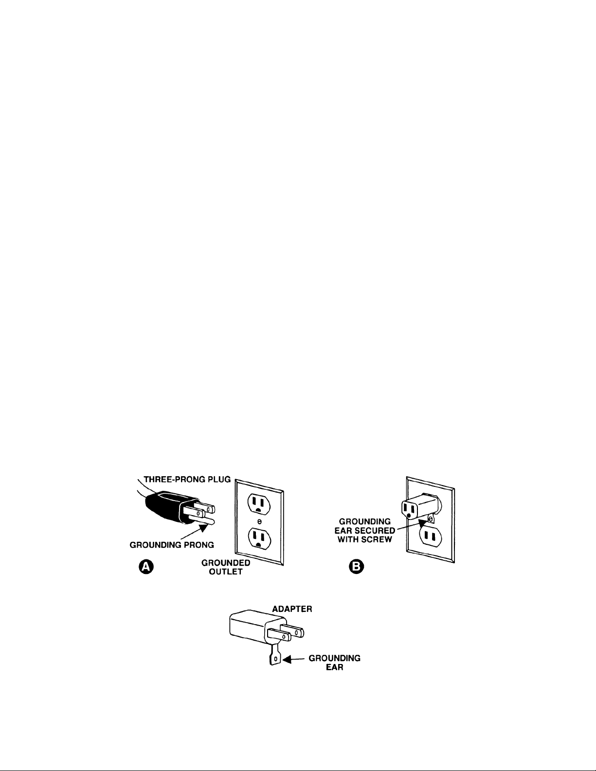
115 Volt Operation
As received fr om the factory, your sander is ready to run at 115 volt operati on. Thi s sander, when wir ed
for 115 volt, i s intended for use on a circuit that has an outlet and a plug that looks li k e the one illustrated
in (A). A temporary adapt er , whic h looks like the adapter as illustrated in ( B ), may be used to connect
this plug to a two-pole receptacle, as shown in (B) if a properly grounded out let is not available. The
temporary adapt er shoul d only be used until a properly grounded outlet c an be inst alled by a qualified
electrician. This ada pte r is not applica ble in Cana da . The green colored rigid ear, lug, or tab,
extending from the adapter, must be connected to a permanent ground such as a properl y gr ounded
outlet box, as shown in (B ).
6

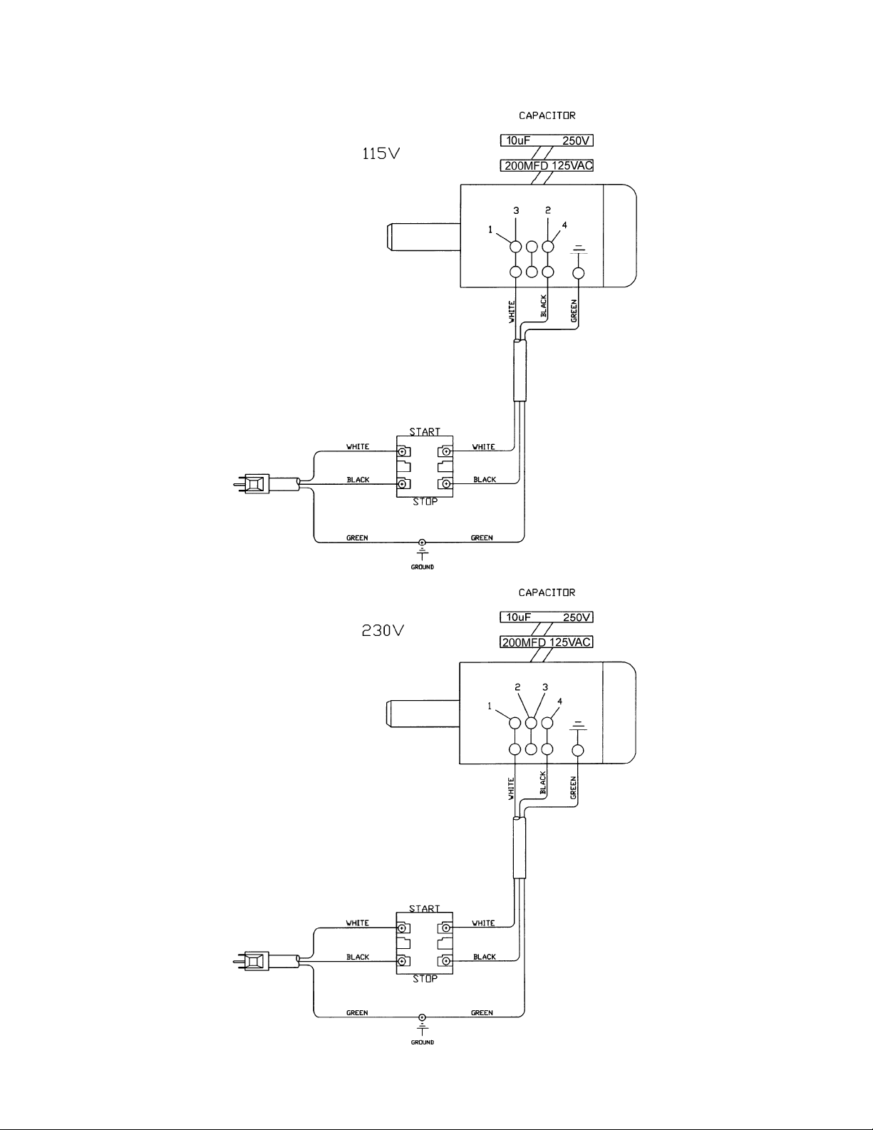
230 Volt Operation
If 230V, singl e phase operat ion is desired, the following instr uc tions must be followed:
1. Disconnect the mach in e f rom the power sou rce.
2. This JET sander is supplied wit h four motor leads that are connected for 115V oper ation, as shown in
Figure A. Reconnect these four motor leads for 230V operation, as shown in Fi gur e B.
3. The 115V attachment plug (A ), suppl ied with the sander, must be replaced with a UL/CSA listed plug
suitable for 230V oper ation (D). Contact your local Authoriz ed J ET S ervice Center or qualified
electrici an for proper procedures to install the pl ug. The sander must com ply with all local and
national codes after the 230 volt plug is installed.
4. The sander with a 230 volt plug shoul d only be c onnec ted to an outlet having the same configuration
(D). No adapter is available or should be used with the 230 volt plug.
Important: In all cases (115 or 230 volt s), make c ertain the receptacle in question is properly grounded.
If you are not sure, have a regi ster ed electrician check the receptac le.
7

Introduction
This manual is provided by JET covering the safe operation and maintenance procedures for a JET Model
JDS-12B Disc Sander. This manual contains instructions on installation, safety precautions, general operating
procedures, maintenance instructions and parts b reakdown. This m achine has been designed and constructed
to provide years of trouble free operation if used in accordance with instructions set forth in this manual. If there
are any questions or comments, please contact either your local supplier or JET. JET can also be reached at
our web s ite: www.jettools.com.
Specifications
Model Number ........................................................................................................................................... JDS-12B
Stock Numbers:
Benchtop model (no filter) ...................................................................................................................... 708433
Open Stand model with filter ................................................................................................................ 708432K
Disc Diameter (in.) .............................................................................................................................................. 12
Table Tilt (deg.) .............................................................................................................................. 15 up, 45 down
Dust Chute Diameter (in.) ..................................................................................................................................... 4
Disc Table (in.) .......................................................................................................................... 16-3/8 W x 9-3/4 D
Abrasive Disc included ................................................................................................................................. 60 Grit
Circle Gauge Accessory, Maximum Diameter (in.) ....................................................................................... 17-3/4
Motor .................................................................................................... TEFC, 1HP, 1PH, 115/230V, 60Hz, 10/5A
Impeller (in.) ................................................................................................................................... 9 Dia. x 1- 13/16
Overall Dimensions (in.) ..................................................................................................... 21 W x 25-5/8 D x 21 H
Net Weight, approximate (lbs.) .......................................................................................................................... 100
The above specifications were current at the time this manual was published, but because of our policy of
continuous improvement, JET reserves the right to change specifications at any time and without prior notice,
without incurring obligations.
Read and understand the entire contents of this manual before attem pting set-up or
operation! Failure to comply may cause serious injury.
8

Unpacking
Open shipping container and check for shipping
damage. Report any damage immediately to your
distributor and shipping agent. Do not discard any
shipping material until the Disc Sander is
assembled and running properly.
Compare the contents of your container with the
following parts list to make sure all parts are intact.
Missing parts, if any, should be reported to your
distributor. Read the instruction manual thoroughly
for assembly, maintenance and safety instru ctions.
Contents of the Shipping Carton
JDS-12B Benchtop Sander
1 Sander
1 Sanding Disc
1 Table
1 Miter Gauge
1 Inlet
1 Inlet Gasket
1 Owner's Manual
1 Warranty Card
1 Hardware Kit
4 Hex Head Bolts M10x40
8 Flat Washers M10
4 Lock Washers M10
4 Hex Nuts M10
4 Hex Head Bolts M6x16
1 Center Point
1 Right Angle Hex Wrench 3mm
1 Filler Bar
1 Socket Head Cap Screw M5x8
OS-12DS Stand (option al accessory)
4 Stand Legs
4 Stand Supports
Hardware Kit
16. Carriage Bolt M8x16
16. Hex Nut M8
CF-12DS Canister Fil t er (o ptional accessory)
1 Canister Filter
1 Plastic Elbow
1 Grounding Wire
Tools Required for Assembly &
Adjustments
1 13mm Wrench or socket
1 Combination Square
(708432K shown with optional stand 708438 and
Canister Filter 708434)
9

Assembly
Stand Assembly (optional accessory)
1. Match the hole patterns in the stand legs with
the hole patterns in the stand supports. Mount
the legs to the outside of the supports using
sixteen M8x16 carriage bolts and sixteen M8
flange lock nuts, Figure 1. Do not tighten until
the stand has been assembled and is sitting
level on the floor.
2. Bolt the sander to the stand with four M10x40
hex cap bolts, eight M10 flat washers, four
M10 lock washers and four M10 hex nuts
Sander Assembly
1. Mount the sander to JET’s open stand with
four M10x40 hex head bolts, eight M10 flat
washers, four lock washers, and four hex nuts.
Tighten the nuts to secure the sander to the
stand.
2. Note: If you are going to use the sander as a
benchtop unit mount the sander to the
workbench with the supplied bolts.
3. Unscrew the knob (A, Figure 2), remove the
washer (B, Figure 2) and t he trunnion holder
(C, Figure 2). Repeat for opposite side.
4. Lift the table (D, Figure 2) into positio n and set
on top of the split pins and threaded shaft.
5. Reinstall the trunnion holder, washer and
knob. Repeat for opposite side.
6. Make sure the trunnion and trunnion holder
engage and tighten the knob.
7. Place the gasket (E, Figure 3) against the
sander base and mount the inlet port (F,
Figure 3) to the sander with four M6x16 hex
cap bolts (G, Figure 3).
Figure 1
Figure 2
Avoid kickback by sanding i n
accordance with directional arrow. Sand on
downward side of disc. Sandi ng on the upward
side could cause the workpiece to fly up
causing injury! Failure to comply may cause
serious injury!
Figure 3
10

Adjustments
Table Adjustment
1. The table stops have been set-up at the
factory. However, if you run into a problem, or
want to check the table follow the below listed
steps.
2. Loosen lock knobs (B, Figure 4) and move the
table to the 90 degree position. Tighten knobs
and place a square (A, Figure 4) aga inst the
table and disc. The square should rest flat
against the table and disc.
3. If adjustment is needed move the table so that
it rests 90 degrees from the table, and loosen
the hex nut (D, Figure 5) and tighten the set
screw (C, Figure 5) until it contacts the table
surface. Tighten hex nuts. This will properly
adjust the 90-degree stop.
4. Loosen the lock knobs (F, Figure 5) and tilt the
table up just enough to pivot the stop (E,
Figure 5) out of the way.
5. Tilt the table down until it hits the 45 degree
stop (G, Figure 5). Tighten lock knobs, and
check the table with a combination square.
Figure 4
6. If adjustment is needed, loosen the hex nut (H,
Figure 5) and adjust the socket head cap
screw (G, Figure 5) until it contacts the table.
Tig ht en hex n uts.
7. Always maintain a gap of approximately 1/16”
between the table edge, and disc. If
adjustment is necessary loosen hex cap bolts
(I, Figure 5) and move the table into position.
Tighten hex cap bolts.
8. The table tilts between 15° up - 45° dow n by
loosening the lock knobs and tilting the table to
the desired angle. Tighten the knobs.
9. If you want to tilt the table up you need to pivot
the stop (E, Figure 5) out of the way.
Sanding Disc Replacement
1. Disconnect machine from the power
source.
2. Remove the knobs (J, Figure 6), washers (K,
Figure 6), and trunnion holders (L, Figure 6)
followed by the table assembly (M, Figure 6).
3. Remove old sanding disc by striping from
wheel. Use a cleaner and putty knife to
remove the residue. Make sure the disc plate
is clean and dry.
Figure 5
4. Press the new disc firmly into place.
Figure 6
11

Circle Gauge
The circl e gauge (A, Figur e 7) provi ded with the
sander can be u se d for sanding circ les up to 173/4” diamet er. Slide t he gauge int o the miter slot
that is perpendicular to the sanding disc. The
radius of the desired circle should be the
distance from the gauge center point to the
sanding disc. Lock the circle gauge in position
by tightening the set screws. Cut the wood to
the approximate diameter and press on to the
center point. Rotate the wood until the desired
results are achieved.
Filler Bar
The filler bar (H, Figure 7) should be added
when sanding small workpieces. Secure in place
with the socket head cap screw (I, Figure 7).
When not using t he filler bar thread t he socket
head cap screw (I, Figure 7) in the t apped hole
as a stop.
Brake
After you hav e turned t he sander “OFF ” you c an
press the brake (B, Figure 7) to slow, or stop the
sanding disc.
Figure 7
On/Off Switch
The machine can be tur ned “ON” by moving the
switch (D, Figure 8) to the “UP” position. The
key (E, Figure 8) can be removed when the
machine is in the “OFF” position. With the key
removed the switch will not operate.
Lubrication
You may need to lubricate the trunnion, and
trunnion holder (G, Figure 8) if the table does
not tilt smoothly .
Motor
Make frequent inspections of the motor fan cover,
and blow out (with low pressure air hose) or
vacuum any accumulation of foreign material in
order to maintain normal motor ventilation.
All electrical connections
must be done by a qualified electrician in
compliance with all relevant codes. All
adjustments or repairs must be done with the
sander disconnected from the power source,
unplugged. Failure to comply may result in
serious injury!
Figure 8
12

The JDS-12B disc sander is rated 115V/230V,
Prewired 115V.
If you want to run the JDS-12B on 230V refer to
the wiring diagram found on the inside of the
switch box cover (F, Figure 8).
Before hooking up to the power so urce, make sure
that the switch is in the off position.
It is recommended that the sander, when operated
at 115 volts, be connected to a dedicated,
minimum 20 amp circuit with a 20 amp circuit
breaker or time delay fuse. W hen operated at 230
volts, connect the sander to a dedicated, minimum
10 amp circuit with 10 amp circuit breaker or time
delay fuse. Local codes take precedence over
recommendations.
Dust Collection
The disc sander has a built in fan designed to suck
the saw dust away from the sanding disc and
exhaust through the inlet (C, Figure 7). For best
results hook the sander to JET’s optional
accessory canister filter (#708434).
The sander can also be attached to a dust
collector using a 4” diameter hose and clamp. JE T
offers a wide variety of hoses, adapters and dust
collectors.
Canister Filter (optional accessory)
1. Remove the inlet port that came with the
sander.
2. Mount the plastic elbow (A, Figure 9) to the
sander using the same hardware (B, Figure 9)
from the inlet port.
3. Connect the filter (C, Figure 9) to the elbow
and turn counter-clockwise so that it locks in
place.
Static electricity will build up
in the filter during operation. The filter ground
must be attached to the machine ground, a nd
to the filter. Failure to comply may result in
fire/loss of property, or personal injury.
4. Remove the screw (D, Figure 9) from the
sander base. Attach the end of the grounding
wire to the screw and thread back in to the
base.
5. Attach the grounding clip (E, Figure 9) to the
metal part of the filter. This will prevent static
electricity from building up in the filter.
Figure 9
Cleaning the Filter
Wearing a particle
mask/respirator for protection against fine dust
particles during cleaning is highly
recommended.
Clean the canister filter frequently to keep the
sander’s performance at its optimum. To clean:
1. Disconnect the machine from the power
source.
2. Take off the grounding clip and remove the
filter (C, Figure 9) by turning clockwise.
3. Empty the contents into an appropriate
container.
4. The filter can be cleaned with a low pressure
air hose. Blow from the outside of t he filter to
clean the dust particles. For best results check
and empty the filter frequ ently.
5. Install the filter and reattach the grounding clip.
13

Troubleshooting
Trouble Probable Cause Remedy
Sander unplugged from wall, or motor. Check all plug connections.
Fuse blown, or circuit breaker tripped. Replace fuse, or reset circuit breaker.
Sander will not start
Cord damaged. Replace cord.
Starting capacitor not functioning. Replace starting capacitor.
Sanding disc does not
come up to speed
Machine vibrates
excessively
Sanded edge not
square
Sanding marks on
wood
Extension cord too light or too long
Low current Contact a qualified electrician
Stand or base on uneven surface
Table not square to sanding disc
Work held still Keep workpiece moving
Wrong grit sanding disc
Feed pressure too great Never force workpiece
Sanding against the grain Sand with the grain
Optional Accessories
Replace with adequate size and length
cord
Adjust stand or base so that it rests
evenly on the floor
Bolt down the base or stand
Use a square to adjust table to sanding
disc
Use coarser grit for stock removal and
fine grit for finis h sanding
708438 Open Stand
708434 Canister Filter, 2 micron
Replacement Parts
Replacement parts are listed on the followi ng pages. To order parts or reach our service departm ent, call 1800-274-6848, Monday through Friday (see our website for business hours, www.jettools.com). Having the
Model Number and Serial Number of your machine available when you call will allow us to serve you quickly
and accurately.
14

Breakdown for JDS-12B Benchtop Disc Sander
15

Parts List for JDS-12B Benchtop Disc Sander
Index No. Part No . Description Size Qty
1 ................ 612131 ...................... Guard Bas e.............................................................. ...................................... 1
2 ................ MH612001................. Motor........................................................................ 1 HP, 1Ph 110V/220V ... 1
.................. JDS12B-MFC ............ Motor Fan Cover (not shown) .................................. ...................................... 1
.................. JDS12B-MF............... Motor Fan (not shown)............................................. ...................................... 1
.................. JDS12B-CS ............... Centrifugal Switch (not shown) ................................ ...................................... 1
.................. JDS12B-CC............... Capacitor Cover (not shown) ................................... ...................................... 1
.................. JDS12B-JBC ............. Junction Box Cover (not shown) .............................. ...................................... 1
.................. JDS12B-SC ............... Starting Capacitor (not shown) ................................ 200MFD, 125VAC ......... 1
.................. JDS12B-RC............... Running Capacitor (not shown) ............................... 10μF, 250V ................... 1
3 ................ KS050565 ................. Key ........................................................................... 5x5x65 .......................... 1
4 ................ 994534 ...................... On/Off Switch........................................................... .... .................................. 1
5 ................ 998621 ...................... Strain Relief ............................................................. ...................................... 1
6 ................ IC100001................... Power Cord .............................................................. ...................................... 1
7 ................ TS-1551071 .............. Sprin g Washer ......................................................... M8 ................................. 4
8 ................ SJ080400 .................. Pan Head Socket Bolt.............................................. M8x2 0 ........................... 4
9 ................ 612132 ...................... Fan Blade ................................................................ 9” ................................... 1
10 .............. 612133 ...................... Partition.................................................................... ...................................... 1
11 .............. SF069200.................. Pan Head Bolt w/Flange .......................................... M6x8 ............................. 5
12 .............. 612134 ...................... Sanding Disc............................................................ ...................................... 1
13 .............. SS060200 ................. Set Screw ................................................................ M6x8 ............................. 1
14 .............. 612113 ...................... Washer .................................................................... ...................................... 1
15 .............. SM089400 ................. Countersunk Head Bolt............................................ M8x16 ........................... 1
16 .............. .................................. 12” Disc Sanding Paper (local purchase) ................ 60G ............................... 1
17 .............. 612136 ...................... Front Cover .............................................................. ...................................... 1
18 .............. SF069200.................. Pan Head Bolt w/Flange .......................................... M6x8 ............................. 5
19 .............. TS-1504071 .............. Socket Head Cap Screw.......................................... M8x35 ........................... 1
20 .............. TS-1540061 .............. Hex Nut .................................................................... M8 ................................. 1
21 .............. TS-1550061 .............. Flat Washer ............................................................. M8x18 ........................... 1
22 .............. 612038 ...................... Trunnion Holder (A) ................................................. ...................................... 1
23 .............. PS062600 ................. Sprin g Pin ................................................................ 6x26 .............................. 4
24 .............. SS081200 ................. Set Screw ................................................................ M8x60 ........................... 2
25 .............. TS-1550061 .............. Flat Washer ............................................................. M8x18 ........................... 2
26 .............. 612098 ...................... Knob (black)............................................................. M8 ................................. 2
27 .............. 612052 ...................... Trunnion Holder (B) ................................................. ...................................... 1
28 .............. 612135 ...................... Table ........................................................................ ...................................... 1
29 .............. 612046 ...................... Trunnion................................................................... ...................................... 2
30 .............. TS-1551061 .............. Lock Washer ............................................................ M8 ................................. 4
31 .............. TS-1490021 .............. Hex Head Bolt.......................................................... M8x16 ........................... 4
32 .............. 612010 ...................... Locating Block ......................................................... ...................................... 1
33 .............. PS053600 ................. Sprin g Pin ................................................................ 5x36 .............................. 1
34 .............. TS-1540041 .............. Hex Nut .................................................................... M6 ................................. 1
35 .............. TS-1523071 .............. Set Screw ................................................................ M6x25 ........................... 1
36 .............. 612116 ...................... Brake ....................................................................... ...................................... 1
37 .............. 612118 ...................... Brake Fixed Base .................................................... ...................................... 1
38 .............. PS042600 ................. Sprin g Pin ................................................................ 4x26 .............................. 1
39 .............. SP040200 ................. Pan Head Bolt.......................................................... M4x10 ........................... 3
40 .............. 612140 ...................... Spring ...................................................................... ...................................... 1
41 .............. WF051210................. Flat Wash er ............................................................. M5x 12 ........................... 1
42 .............. 612115 ...................... Stop Handle ............................................................. ...................................... 1
43 .............. TS-1491061 .............. Hex Head Bolt * ....................................................... M10x40 ......................... 4
44 .............. TS-1550071 .............. Flat Washer * ........................................................... M10x20 ......................... 8
45 .............. TS-1551071 .............. Lock Washer * ......................................................... M10 ............................... 4
46 .............. TS-1540072 .............. Hex Nut * ................................................................. M10 ............................... 4
47 .............. 612137 ...................... Packing .................................................................... ...................................... 1
48 .............. 612145 ...................... Inlet .......................................................................... 4” ................................... 1
49 .............. TS-1482031 .............. Hex Head Bolt * ....................................................... M6x 1 6 ........................... 4
50 .............. 612099 ...................... Sponge .................................................................... ...................................... 1
51 .............. TS-1551021 .............. Lock Washer ............................................................ M4 ................................. 2
52 .............. AB198101 ................. Mi ter Gauge Assembly ............................................ ...................................... 1
53 .............. AB612143 ................. Circle Gauge Assembly (ASM) ................................ ...................................... 1
16

Index No. Part No . Description Size Qty
57 .............. 612117 ...................... Sponge Gasket ........................................................ ...................................... 1
58 .............. SP059200 ................. Pan Head Bolt.......................................................... M5x8 ............................. 1
59 .............. WE050000 ................ Star Washer ............................................................. M5 ................................. 1
60 .............. 612171 ...................... Filler Bar .................................................................. ...................................... 1
61 .............. TS-1502011 .............. Socket Head Cap Screw.......................................... M5x8 ............................. 1
* ................. JDS12B-HK ............... Hardware Kit (includes # 43-46, 49, and a 3mm hex wrench) ..........................
.................. JDS12B- WL .............. Warnin g Label (not shown) ...................................... ........................................
.................. JDS12B-ID ................ I .D. Label (not shown).............................................. ........................................
.................. JDS12B-JL ................ JET Label (not shown) ............................................. ........................................
Optional Accessory – F il t er
54 .............. 612147 ...................... Elbow ....................................................................... ...................................... 1
55 .............. 331022 ...................... Filter ......................................................................... ...................................... 1
56 .............. 331033 ...................... Grounding Clip ......................................................... ...................................... 1
17

Open Stand Assembly (Optional Accessory)
Index No. Part No . Description Size Qty
1 ................ 612141 ...................... Stand Leg ................................................................ ...................................... 4
2 ................ 612142 ...................... Stand Support .......................................................... ...................................... 4
3 ................ SC089400 ................. Carriage Bolt ............................................................ M8x16 ......................... 16
4 ................ NF081300 ................. Flange Lock Nut....................................................... M8 ............................... 16
* ................. OS12DS-HK .............. Hardware Kit (not shown) ........................................ ........................................
18
Electrical Connections
19

427 New Sanford Road
LaVergne, Tennessee 37086
Phone: 800-274-6848
www.jettools.com
20
 Loading...