


Operating Instructions and Parts Manual
Metalworking Dust Collection Stand
Model JDCS-505
JET
427 New Sanford Road
LaVergne, Tennessee 37086 Part No. M-414800
Ph.: 800-274-6848 Edition 7 12/2020
www.jettools.com Copyright © 2016 JET

1.0 IMPORTANT SAFETY
INSTRUCTIONS
When using an electrical appliance, basic
precautions should always be followed, including
the following:
READ ALL INSTRUCTIONS BEFORE USING THIS
DUST COLLECTOR.
WARNING – To reduce the risk of fire,
electric shock, or injury:
1. Read and understand entire owner’s manual
before attempting assembly or operation of this
dust collector.
2. Read and understand the warnings posted on
the machine and in this manual.
3. Replace warning labels if they become
obscured or removed.
4. This dust collection stand is designed and
intended for use by properly trained and
experienced personnel only. If you are not
familiar with the proper and safe operation of a
dust collector, do not use until proper training
and knowledge have been obtained.
5. Do not use this dust collection stand for other
than its intended use. If used for other
purposes, JET disclaims any real or implied
warranty and holds itself harmless from any
injury that may result from that use.
6. Always wear approved safety glasses/face
shield while using this dust collection stand.
Everyday eyeglasses only have impact
resistant lenses; they are not safety glasses.
7. Keep hair, loose clothing, fingers, and all parts
of body away from openings and moving parts.
8. Wear hearing protection (plugs or muffs) during
extended periods of operation.
9. Do not operate this machine while tired or under
the influence of drugs, alcohol or any
medication.
10. Make certain the switch is in the OFF position
before connecting the machine to the power
supply. Turn off all controls before unplugging.
11. Make certain the machine is properly grounded.
Connect to a properly grounded outlet only. See
Grounding instructions.
12. Make all machine adjustments or maintenance
with the machine unplugged from the power
source.
13. Remove adjusting keys and wrenches. Form a
habit of checking to see that keys and adjusting
wrenches are removed from the machine
before turning it on.
14. Keep safety guards in place at all times when
the machine is in use. If removed for
maintenance purposes, use extreme caution
and replace the guards immediately after
maintenance is complete.
15. Check damaged parts. Before further use of the
machine, a guard or other part that is damaged
should be carefully checked to determine that it
will operate properly and perform its intended
function. Check for alignment of moving parts,
binding of moving parts, breakage of parts,
mounting and any other conditions that may
affect its operation. A guard or other part that is
damaged should be properly repaired or
replaced.
16. Provide for adequate space surrounding work
area and non-glare, overhead lighting.
17. Keep the floor around the machine clean and
free of scrap material, oil and grease.
18. Keep visitors a safe distance from the work
area. Keep children away.
19. Make your workshop child proof with padlocks,
master switches or by removing starter keys.
20. Give your work undivided attention. Looking
around, carrying on a conversation and “horseplay” are careless acts that can result in serious
injury.
21. The dust collection stand is intended for indoor
use. To reduce the risk of electric shock, do not
use outdoors or on wet surfaces.
22. Do not use to pick up anything that is burning or
smoking, such as cigarettes, matches or hot
ashes.
23. Do not use to pick up flammable or combustible
liquids such as gasoline, or use in areas where
they may be present.
24. Do not pull or carry by cord, use cord as a
handle, close a door on cord, or pull cord
around sharp edges or corners. Do not run dust
collector over cord. Keep cord away from
heated surfaces.
25. Do not use this dust collector with a damaged
cord or plug. If the unit is not working as it
should, has been dropped, damaged, left
outdoors, or dropped into water, return it to a
service center.
26. Do not unplug by pulling on cord. To unplug,
grasp the plug, not the cord.
27. Do not use without dust bag and/or filters in
place.
2

28. Do not handle plug or machine with wet hands.
29. Do not put any objects into the openings. Do not
use with any opening blocked; keep free of
dust, lint, hair, and anything that may reduce air
flow.
30. Do not operate without hose connected to the
inlet. Place cap on unused inlet port. Hazardous
moving parts inside. Unplug before removing or
connecting inlet or inlet guard.
31. Use recommended accessories; improper
accessories may be hazardous.
32. Maintain tools with care. Follow instructions for
lubricating and changing accessories.
33. Turn off machine and disconnect from power
before cleaning. Use a brush or compressed air
to remove chips or debris; do not use bare
hands.
34. Do not leave the machine when it is plugged in.
Unplug from outlet when not in use and before
servicing.
35. Do not stand on the machine. Serious injury
could occur if the machine tips over.
36. The dust collector is intended for industrial use
only.
37. Never mix ferrous and non-ferrous metal dust in
the same dust collector. If you are not familiar
with the proper and safe usage of metal dust
collection systems do not use until proper
training has been obtained.
WARNING: This product can expose you to
chemicals including lead and cadmium which
are known to the State of California to cause
cancer and birth defects or other reproductive
harm, and phthalates which are known to the
State of California to cause birth defects or other
reproductive harm. For more information go to
http://www.p65warnings.ca.gov.
WARNING: Some dust, fumes and gases
created by power sanding, sawing, grinding,
drilling, welding and other construction activities
contain chemicals known to the State of
California to cause cancer and birth defects or
other reproductive harm. Some examples of
these chemicals are:
lead from lead based paint
crystalline silica from bricks, cement and
other masonry products
arsenic and chromium from chemically
treated lumber
Your risk of exposure varies, depending on how
often you do this type of work. To reduce your
exposure to these chemicals, work in a wellventilated area and work with approved safety
equipment, such as dust masks that are
specifically designed to filter out microscopic
particles. For more information go to
http://www.p65warnings.ca.gov/ and http://www.
p65warnings.ca.gov/ wood.
Familiarize yourself with the following safety notices used in this manual:
This means that if precautions are not heeded, it may result in minor injury and/or possible
machine damage.
This means that if precautions are not heeded, it may result in serious, or possibly even fatal,
injury.
SAVE THESE INSTRUCTIONS
2.0 About this manual
This manual is provided by JET, covering the safe operation and maintenance procedures for a JET Model JDCS505 Metalworking Dust Collection Stand. This manual contains instructions on installation, safety precautions,
general operating procedures, maintenance instructions and parts breakdown. The dust collector has been
designed and constructed to provide consistent, long-term operation if used in accordance with the instructions
as set forth in this document.
If there are questions or comments, please contact your local supplier or JET. JET can also be reached at our
web site: www.jettools.com.
Retain this manual for future reference. If the machine transfers ownership, the manual should accompany it.
3

3.0 Table of contents
Section Page
1.0 IMPORTANT SAFETY INSTRUCTIONS ....................................................................................................... 2
2.0 About this manual .......................................................................................................................................... 3
3.0 Table of contents ............................................................................................................................................ 4
4.0 Specifications ................................................................................................................................................. 5
4.1 Mounting hole dimensions .......................................................................................................................... 6
5.0 Setup and assembly ....................................................................................................................................... 8
5.1 Unpacking and cleanup .............................................................................................................................. 8
5.2 Shipping contents ....................................................................................................................................... 8
5.3 Tools required for assembly: ...................................................................................................................... 8
5.4 Assembly .................................................................................................................................................... 8
5.5 Mounting a tool ........................................................................................................................................... 8
5.6 Adaptor plate (optional) .............................................................................................................................. 8
6.0 Electrical connections .................................................................................................................................... 9
6.1 GROUNDING INSTRUCTIONS ................................................................................................................. 9
6.2 Extension cords .......................................................................................................................................... 9
7.0 Operations .................................................................................................................................................... 10
7.1 Main switch ............................................................................................................................................... 10
7.2 Safety key ................................................................................................................................................. 10
7.3 Thermal relay ........................................................................................................................................... 10
8.0 User-maintenance ........................................................................................................................................ 10
9.0 Optional accessories .................................................................................................................................... 10
10.0 Replacement Parts ..................................................................................................................................... 10
10.1.1 JDCS-505 Grinder Stand – Exploded View ......................................................................................... 11
10.1.2 JDCS-505 Grinder Stand – Parts List ................................................................................................. 12
11.0 Electrical Connections for JDCS-505 ......................................................................................................... 14
12.0 Warranty and service ................................................................................................................................. 15
4

4.0 Specifications
Model number ........................................................................................................................................ JDCS-505
Stock number .............................................................................................................................................. 414800
Motor and electricals:
Motor type ..................................................................................................................... induction, cap acitor run
Horsepower .......................................................................................................................... 1/2 HP (0.375 kW)
Phase ........................................................................................................................................................ single
Voltage ....................................................................................................................................................... 115V
Cycle .......................................................................................................................................................... 60Hz
Listed FLA (full load amps) ........................................................................................................................ 4.5 A
Starting amps ............................................................................................................................................... 30A
Running amps (no load) .............................................................................................................................. 2.4A
Run capacitor ............................................................................................................ 300VAC, 15F C/us listed
On/off switch .................................................................................. mushroom style with removable safety key
Motor speed ...................................................................................................................................... 3450 RPM
Power cord ................................................................... 14 AWG (2.08mm
Power plug ............................................................................................................... 5-15P, 125V/20A installed
Recommended circuit size
Sound emission
2
................................................................................................................ 75 dB at 9.84 ft./3m
1
......................................................................................................................... 10A
Performance:
Inlet diameter ................................................................................................................................ 5 in. (127 mm)
Inlet adaptor ports, number of ............................................................................................................................ 2
Inlet adaptor ports, diameter of ..................................................................................................... 3in. (76.2 mm)
Filter efficiency ........................................................................................................... 90% of 50 micron particles
Air Flow with filters installed ............................................................................................ 472 CFM (22.65 m
Air Velocity ......................................................................................................................... 3465 FPM (17.6 m/s)
Static pressure loss (WC) ............................................................................................ 0.748 inH
Maximum static pressure loss (WC) .............................................................................. 2.44 inH
Impeller:
Impeller diameter ..................................................................................................................... 6.69 in. (170 mm)
Impeller type .......................................................................................................................................... radial fin
Impeller material .......................................................................................................................................... steel
Filter:
Filter type ........................................................................................ 50 micron, non-woven heat-resistant cotton
Filter size (L x W x D) ........................................................... 13-1/2 x 6-7/8 x 2-1/2 in. (343 x 174.6 x 63.5 mm)
Filter surface area ...................................................................................................................... 0.25 m
Filter efficiency ........................................................................................................... 90% of 50 micron particles
Collection drawer:
Capacity .................................................................................................................................... 2.29 gal. (3.79 L)
Dimensions .......................................................................... 12.2 L x 8.66 W x 5.11 D in. (310 x 220 x 130 mm)
Material ........................................................................................................................................................ steel
Main materials:
Frame ........................................................................................................................... 16 ga. steel, 1.6mm thk.
Paint type/finish .............................................................................................................................. powder coat
Dimensions:
Footprint ..................................................................................................... 15.5 L x 15.9 W in. (396 x 406 mm)
Top of stand from floor (approximate) ....................................................................................... 35 in. (889 mm)
Overall dimensions, shipping carton ................................ 18.1 L x 18.1 W x 39.8 H in. (460 x 460 x 1010 mm)
Overall dimensions, assembled ....................................... 15.5 L x 15.9 W x 34.25 H in. (396 x 406 x 870 mm)
1
Subject to local/national electrical codes.
2
The specified values are emission levels and are not necessarily to be seen as safe operating levels. As workplace
conditions vary, this information is intended to allow the user to make a better estimation of the hazards and risks
involved only.
2
, x 3C, 6 ft. (183cm), SJT, UL listed
3
/hr)
O (19 mmH2O)
2
O (62 mmH2O)
2
2 (
2.70 ft2)
5

Dust ports:
Main dust port, outside diameter ................................................................................................. 5 in. (127 mm)
Inlet adaptor ports, outside diameter ............................................................................... two at 3 in. (76.2 mm)
Weights:
Net weight ............................................................................................................................... 92.4 lb. (41.9 kg)
Shipping weight ........................................................................................................................... 110 lb. (50 kg)
The specifications in this manual were current at time of publication, but because of our policy of continuous
improvement, JET reserves the right to change specifications at any time and without prior notice, without
incurring obligations.
4.1 Mounting hole dimensions
4.1.1 Dust collection stand
Figure 1: Hole pattern on dust collection stand
6

4.1.2 Adaptor plate (optional accessory #414830)
Figure 2: Hole pattern on adaptor plate (OPTIONAL ACCESSORY p/n 414830)
7

Read and understand the
entire contents of this manual before attempting
assembly or operation. Failure to comply may
cause serious injury.
5.0 Setup and assembly
5.1 Unpacking and cleanup
Remove all contents from shipping carton, and
remove accessories from drawer inside stand.
Compare parts to the contents list in this manual. If
shipping damage or any part shortages are
identified, contact your distributor. Do not discard
carton or packing material until dust collector is
assembled and running satisfactorily.
5.2 Shipping contents
Carton contents (see Figure 2)
1 Grinder stand
2 Water trays (L and R)
1 Inlet adaptor assembly
4 Foot pads
1 Open end wrench 10/12 mm
5.3 Tools required for assembly:
10/12mm wrench – provided
5.5 Mounting a tool
Position tool, such as grinder or sander (not
provided) atop stand and secure with fasteners
through the hole/slot pattern. Connect 3-inch dust
hose (optional accessory) to inlet adaptor port and
tool, and secure with hose clamps.
IMPORTANT: An inlet port that is not used during
operation should be capped. An open port will
diminish the efficiency of the dust collector and may
present a safety hazard.
5.6 Adaptor plate (optional)
An adaptor plate kit (optional accessory, p/n
#414830) is available, and will accept tools with
different mounting hole patterns.
To install adaptor plate kit:
1. Install left and right supports (A, Figure 13) to
stand with 1/4 in. screws.
2. Install adaptor plate (B) to supports with 1/4 in.
screws, and secure to top of stand with 5/16 in.
screws.
3. Mount tool to adaptor plate, and secure with
appropriate fasteners.
Table 1 shows JET machines that will mount to
either the stand or the adaptor plate.
5.4 Assembly
1. Install foot pads beneath corners of stand.
Rotate pads to adjust height at each corner until
stand is level.
2. Install inlet adaptor onto dust port and secure
with screw (A, Figure 3).
Inlet adaptor should be
installed before plugging in or operating
dust collector.
3. Place water trays (left and right version) into the
recesses on front of stand.
Figure 4
JET Tool stock no. mounts to:
IBG-8 Grinder* 578008 Stand
IBG-10 Grinder* 578010 Stand
JBG-6A Grinder 577101 Stand
JBG-8A Grinder 577102 Stand
JBG-10A Grinder 577103 Stand
*Connect IBG Bench grinders to stand using
414811 hose and 414825 reducer.
Table 1
Figure 3
8
6.0 Electrical connections
All electrical connections must
be done by a qualified electrician in compliance
with all local codes and ordinances. Failure to
comply may result in serious injury.
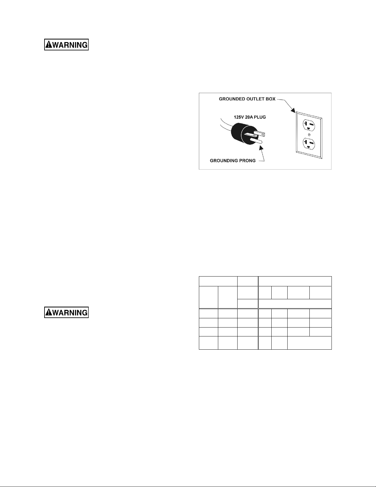
This appliance is rated more than 15 Amp. The dust
collection stand comes with a plug designed for use
on a circuit with a grounded outlet that looks like the
one pictured in Figure 5.
IMPORTANT: Due to high starting current
demands, it is not recommended to use this plug for
belt style grinders.
Keep in mind that a circuit being used by other
machines, tools, lights, heaters, etc., at the same
time will add to the electrical load. A dedicated
circuit to the dust collection stand will offer best
results since dust collectors are generally used
while other tools are running.
Before connecting to power source, be sure switch
is in off position.
It is recommended that the dust collection stand be
connected to a dedicated 20 amp circuit with circuit
breaker or fuse. If connected to a circuit protected
by fuses, use time delay fuse marked “D”. Local
codes take precedence over recommendations.
6.1 GROUNDING INSTRUCTIONS
This appliance must be grounded. If it should
malfunction or breakdown, grounding provides a
path of least resistance for electric current to reduce
the risk of electric shock. This appliance is equipped
with a cord having an equipment-grounding
conductor and grounding plug. The plug must be
inserted into an appropriate outlet that is properly
installed and grounded in accordance with all local
codes and ordinances.
Improper connection of the
equipment-grounding conductor can result in a
risk of electric shock. Check with a qualified
electrician or service person if you are in doubt
as to whether the outlet is properly grounded.
Do not modify the plug provided with the
appliance – if it will not fit the outlet, have a
proper outlet installed by a qualified electrician.
The conductor with insulation having an outer
surface that is green with or without yellow stripes is
the equipment-grounding conductor. If repair or
replacement of the electric cord or plug is
necessary, do not connect the equipment-grounding
conductor to a live terminal.
Use only 3-wire extension cords that have 3-prong
grounding plugs and 3-pole receptacles that accept
the tool's plug.
Repair or replace damaged or worn cord
immediately.
This appliance is rated more than 15 A and is for use
on a circuit having a nominal rating of 120 V. It is
factory-equipped with a specific electric cord and
plug to permit connection to a proper electric circuit.
Make sure that the appliance is connected to an
outlet having the same configuration as the plug. No
adaptor should be used with this appliance. If the
appliance must be reconnected for use on a
different type of electric circuit, the reconnection
should be made by qualified service personnel.
Figure 5
6.2 Extension cords
The use of extension cords is discouraged; try to
position machines near the power source. If an
extension cord is necessary, make sure it is in good
condition. When using an extension cord, be sure to
use one heavy enough to carry the current your
product will draw. An undersized cord will cause a
drop in line voltage resulting in loss of power and
overheating. Table 2 shows correct size to use
depending on cord length and nameplate ampere
rating. If in doubt, use the next heavier gauge. The
smaller the gauge number, the heavier the cord.
Amp Rating Volts Total length of cord in feet
More
Than
0 6 18 16 16 14
6 10 18 16 14 12
10 12 16 16 14 12
12 16 14 12
Not
More
Than
120
240
AWG
Table 2: Extension cord recommendations
25
50
50
100
100
200
Not
Recommended
150
300
9
7.0 Operations
8.0 User-maintenance
Do not mix ferrous and non-
ferrous metal dust in the same dust collector.
Failure to comply will result in increased risk of
fire.
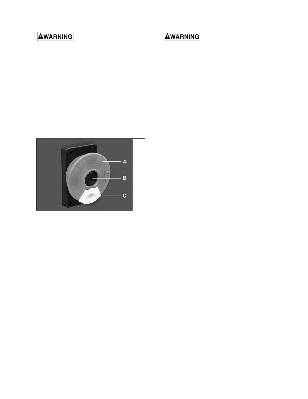
7.1 Main switch
Pull out on switch (A, Figure 6) to start machine.
Green power indicator lamp (B) will illuminate.
Push switch in to stop machine. (Power indicator
lamp will turn off.)
7.2 Safety key
The safety key (C, Figure 6) prevents unauthorized
use of machine. Remove key to deactivate switch.
Key must be reinserted to start machine – press until
it snaps back in.
Figure 6
7.3 Thermal relay
The dust collector has a thermal relay which shuts
off the machine to prevent damage to the motor if
there is an excessive current inrush or the motor is
overloaded.
If the machine shuts off due to overload, push the
stop switch. Allow machine to cool for a few
moments, then press the breaker reset button
located near the power cord entry on right side of
machine. Pull out start button to restart machine.
Always disconnect power to
the machine before performing maintenance.
Failure to do this may result in serious personal
injury.
Keep dust collection stand clean. Brush away chips
and debris after use.
Periodically empty collection drawer and clean out
interior of dust collector stand.
Replace filter after maximum 800 hours of use.
Inspect power cord; have damaged or worn cord
replaced before operating dust collector.
Any other servicing should be performed by an
authorized service representative.
9.0 Optional accessories
The following accessories are available for the
JDCS-505 Dust Collection Stand, and are ordered
separately.
414830 Adaptor Plate Kit
414815 Reducer, 3 in. to 1.5 in.
414820 Reducer, 3 in. to 2 in.
414825 Reducer, 3 in. to 2.5 in.
414811 0.6M Hose, Heat Resistant, ø2.5 x 24.4 in.
414812 0.6M Hose, Heat Resistant, ø2 x 24.4 in.
414813 0.6M Hose, Heat Resistant, ø3 x 24.4 in.
10.0 Replacement Parts
Replacement parts are listed on the following pages. To order parts or reach our service department, call 1-800274-6848 Monday through Friday, 8:00 a.m. to 5:00 p.m. CST. Having the Model Number and Serial Number of
your machine available when you call will allow us to serve you quickly and accurately.
Non-proprietary parts, such as fasteners, can be found at local hardware stores, or may be ordered from JET.
Some parts are shown for reference only, and may not be available individually.
10
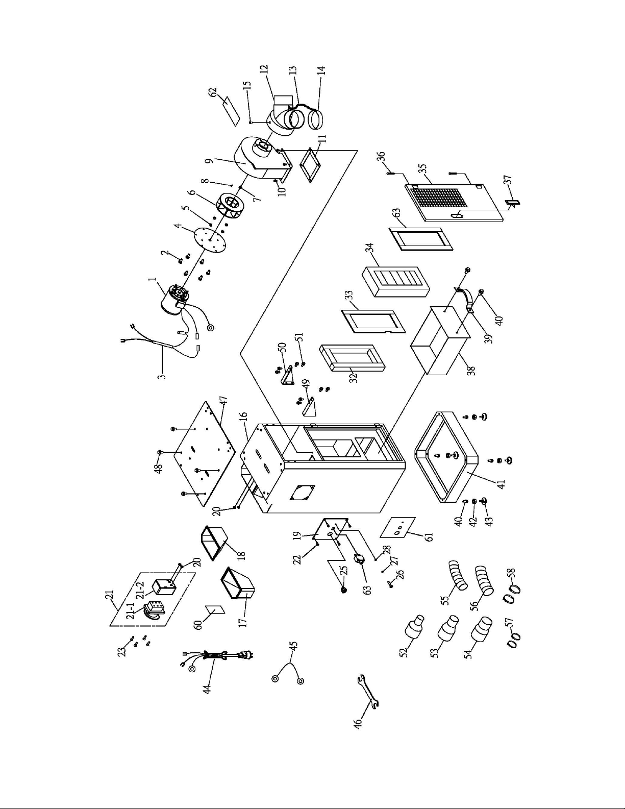
10.1.1 JDCS-505 Grinder Stand – Exploded View
11

10.1.2 JDCS-505 Grinder Stand – Parts List
Index No Part No Description Size Qty
1 ................ JDCS505-01 .............. Motor ....................................................................... 1/2 HP ........................... 1
.................. JDCS505-RC ............ Run Capacitor .......................................................... 300VAC 15F ............... 1
2 ................ F000299 .................... Phillips Pan Head Screw ......................................... 1/4 x 1/2 in. ................... 6
3 ................ JDCS505-03 .............. Motor Cord ............................................................... ...................................... 1
4 ................ JDCS505-04 .............. Motor Plate .............................................................. Ø215 x 3t mm ............... 1
5 ................ F001692 .................... Lock Nut .................................................................. M4 ................................. 4
6 ................ JDCS505-06 .............. Impeller .................................................................... ...................................... 1
7 ................ F001698 .................... Lock Nut .................................................................. M10-1.5 ......................... 1
8 ................ EGH1880-1-A07 ........ Key .......................................................................... 4x4x20 mm ................... 1
9 ................ JDCS505-09 .............. Impeller Housing ...................................................... ...................................... 1
10 .............. F012430 .................... Hex Flange Screw ................................................... 1/4 x 1/2 in. .................. 4
11 .............. JDCS505-11 .............. Gasket ..................................................................... ...................................... 1
.................. JDCS505-12A ........... Inlet Adaptor Assembly (includes #12,13,14) .......... ...................................... 1
12 .............. JDCS505-12 .............. Inlet Adaptor ............................................................ Ø3 in.(x2) ...................... 1
13 .............. JDCS505-13 .............. Chain ....................................................................... ...................................... 1
14 .............. 414835 ...................... End Cap ................................................................... Ø3 in ............................. 1
15 .............. F008319 .................... Hex Cap Bolt ........................................................... #10-24 x 3/8 in. ............. 1
16 .............. JDCS505-16 .............. Main Body ................................................................ ...................................... 1
17 .............. JDCS505-17 .............. Right Tray ................................................................ ...................................... 1
18 .............. JDCS505-18 .............. Left Tray .................................................................. ...................................... 1
19 .............. JDCS505-19 .............. Plate ........................................................................ ...................................... 1
20 .............. JDCS505-20 .............. Bushing .................................................................... ...................................... 4
21 .............. JDCS505-21 .............. Switch Assembly (includes # 21-1, 21-2, 21-3) ....... ...................................... 1
21-1 ........... JDCS505-21-1 .......... Switch Base ............................................................. ...................................... 1
21-2 ........... JDCS505-21-2 .......... Switch Cover ........................................................... ...................................... 1
21-3 ........... JDC-500022-SC ........ Safety Key (not shown)............................................ ...................................... 1
22 .............. F000652 .................... Phillips Flange Head Screw ..................................... 3/16 x 3/8 in. ................. 2
23 .............. JDCS505-23 .............. Phillips Head Sheet Metal Screw............................. M3x12 ........................... 4
25 .............. JDCS505-25 .............. Strain Relief ............................................................. 8R-1 .............................. 1
26 .............. F000233 .................... Phillips Pan Head Screw ......................................... 3/16 x 1/2 in. ................. 1
27 .............. F001977 .................... Lock Washer External Tooth ................................... #10-24 in ....................... 1
28 .............. F002973 .................... Hex Nut .................................................................... #10-24 in ....................... 1
32 .............. JDCS505-32 .............. Foam Strip ............................................................... 1/2 in. W ........................ 1
33 .............. JDCS505-33 .............. Foam Strip ............................................................... 7/8 in. W ........................ 1
34 .............. 414840 ...................... Filter ......................................................................... 340x172x60mm/50 ..... 1
35 .............. JDCS505-35 .............. Door ......................................................................... ...................................... 1
36 .............. JDCS505-36 .............. Bolt .......................................................................... ...................................... 1
37 .............. JDCS505-37 .............. Door Latch ............................................................... ...................................... 1
38 .............. JDCS505-38 .............. Drawer ..................................................................... ...................................... 1
39 .............. JDCS505-39 .............. Handle ..................................................................... ...................................... 1
40 .............. F012439 .................... Hex Flange Screw ................................................... 5/16 x 1/2
41 .............. JDCS505-41 .............. Base ........................................................................ 450x450x1.6t ................ 1
42 .............. F002957 .................... Hex Nut .................................................................... 3/8 in. ............................ 4
43 .............. JDCS505-43 .............. Foot Pad .................................................................. 3/8 x 2 in. ...................... 4
44 .............. JDCS505-44N ........... Power Cord .............................................................. 5-50P / 2.08mm
45 .............. JDCS505-45 .............. Ground Wire ............................................................ ...................................... 1
46…….GH1340A-TBCP-16-04 .... Open-end Wrench ................................................... 10/12 mm ...................... 1
59 .............. JET-165 ..................... JET Logo with Adhesive (not shown) ...................... 165x68mm .................... 1
60 .............. LM000083 ................. ID/Warning Label, JDCS-505 .................................. ...................................... 1
61 .............. LM000084N ............... Caution Label .......................................................... ...................................... 1
62 .............. LM000085 ................. Caution Label – Adaptor .......................................... ...................................... 1
63 .............. JDCS505-63 .............. Thermal Control Relay ............................................. 10A ............................... 1
in. ................. 6
2
........... 1
12

Optional parts:
.................. 414830 ...................... Adaptor Plate Kit * (incl. #47 thru 51) ...................... ...................................... 1
47 .............. .................................. Adaptor Plate * ........................................................ ...................................... 1
48 .............. F012439 .................... Hex Flange Screw * ................................................. 5/16 x 1/2 in. ................. 4
49 .............. JDCS505-49 .............. Left Support * ........................................................... ...................................... 1
50 .............. JDCS505-50 .............. Right Support * ........................................................ ...................................... 1
51 .............. F012430 .................... Hex Flange Screw * ................................................. 1/4 x 1/2 in. ................... 8
52 .............. 414815 ...................... Reducer * ................................................................. 3 to 1.5 in. ..................... 1
53 .............. 414820 ...................... Reducer * ................................................................. 3 to 2 in ......................... 1
54 .............. 414825 ...................... Reducer * ................................................................. 3 to 2.5 in. ..................... 1
55 .............. 414812 ...................... 0.6M Hose, Heat Resistant * ................................... Ø2 x 24.4 in. ................. 1
56 .............. 414813 ...................... 0.6M Hose, Heat Resistant * ................................... Ø3 x 24.4 in. ................. 1
57 .............. 605417 ...................... Wire Hose Clamp * .................................................. Ø2 in. ............................ 2
58 .............. JDCS505-58 .............. Wire Hose Clamp * .................................................. Ø3 in. ............................ 2
59 .............. 414811 ...................... 0.6M Hose, Heat Resistant * (not shown) ............... Ø2.5 x 24.4 in. .............. 1
Parts with asterisk (*) are optional and ordered separately.
Some parts may be shown for reference only, and not available individually.
13

11.0 Electrical Connections for JDCS-505
14

12.0 Warranty and service
JET warrants every product it sells against manufacturers’ defects. If one of our tools needs service or repair, please
contact Technical Service by calling 1-800-274-6846, 8AM to 5PM CST, Monday through Friday.
Warranty Period
The general warranty lasts for the time period specified in the literature included with your product or on the official
JET branded website.
JET products carry a limited warranty which varies in duration based upon the product. (See chart below)
Accessories carry a limited warranty of one year from the date of receipt.
Consumable items are defined as expendable parts or accessories expected to become inoperable within a
reasonable amount of use and are covered by a 90 day limited warranty against manufacturer’s defects.
Who is Covered
This warranty covers only the initial purchaser of the product from the date of delivery.
What is Covered
This warranty covers any defects in workmanship or materials subject to the limitations stated below. This warranty
does not cover failures due directly or indirectly to misuse, abuse, negligence or accidents, normal wear-and-tear,
improper repair, alterations or lack of maintenance. JET woodworking machinery is designed to be used with Wood.
Use of these machines in the processing of metal, plastics, or other materials outside recommended guidelines may
void the warranty. The exceptions are acrylics and other natural items that are made specifically for wood turning.
Warranty Limitations
Woodworking products with a Five Year Warranty that are used for commercial or industrial purposes default to a
Two Year Warranty. Please contact Technical Service at 1-800-274-6846 for further clarification.
How to Get Technical Support
Please contact Technical Service by calling 1-800-274-6846. Please note that you will be asked to provide proof
of initial purchase when calling. If a product requires further inspection, the Technical Service representative will
explain and assist with any additional action needed. JET has Authorized Service Centers located throughout the
United States. For the name of an Authorized Service Center in your area call 1-800-274-6846 or use the Service
Center Locator on the JET website.
More Information
JET is constantly adding new products. For complete, up-to-date product information, check with your local distributor
or visit the JET website.
How State Law Applies
This warranty gives you specific legal rights, subject to applicable state law.
Limitations on This Warranty
JET LIMITS ALL IMPLIED WARRANTIES TO THE PERIOD OF THE LIMITED WARRANTY FOR EACH PRODUCT.
EXCEPT AS STATED HEREIN, ANY IMPLIED WARRANTIES OF MERCHANTABILITY AND FITNESS FOR A
PARTICULAR PURPOSE ARE EXCLUDED. SOME STATES DO NOT ALLOW LIMITATIONS ON HOW LONG AN
IMPLIED WARRANTY LASTS, SO THE ABOVE LIMITATION MAY NOT APPLY TO YOU.
JET SHALL IN NO EVENT BE LIABLE FOR DEATH, INJURIES TO PERSONS OR PROPERTY, OR FOR
INCIDENTAL, CONTINGENT, SPECIAL, OR CONSEQUENTIAL DAMAGES ARISING FROM THE USE OF OUR
PRODUCTS. SOME STATES DO NOT ALLOW THE EXCLUSION OR LIMITATION OF INCIDENTAL OR
CONSEQUENTIAL DAMAGES, SO THE ABOVE LIMITATION OR EXCLUSION MAY NOT APPLY TO YOU.
JET sells through distributors only. The specifications listed in JET printed materials and on official JET website are
given as general information and are not binding. JET reserves the right to effect at any time, without prior notice,
those alterations to parts, fittings, and accessory equipment which they may deem necessary for any reason
whatsoever. JET
Product Listing with Warranty Period
90 Days – Parts; Consumable items
1 Year – Motors; Machine Accessories
2 Year – Metalworking Machinery; Electric Hoists, Electric Hoist Accessories; Woodworking Machinery used
for industrial or commercial purposes
5 Year – Woodworking Machinery
Limited Lifetime – JET Parallel clamps; VOLT Series Electric Hoists; Manual Hoists; Manual Hoist
Accessories; Shop Tools; Warehouse & Dock products; Hand Tools; Air Tools
NOTE: JET is a division of JPW Industries, Inc. References in this document to JET also apply to JPW Industries,
Inc., or any of its successors in interest to the JET brand.
®
branded products are not sold in Canada by JPW Industries, Inc.
15

427 New Sanford Road
LaVergne, Tennessee 37086
Phone: 800-274-6848
www.jettools.com
16
 Loading...