

Operating Instructions and Parts Manual
12” and 14” Abrasive Cut-off Saws
Models AB-12, AB-14
For machines with serial no. 16110010 and higher
JET
427 New Sanford Road
LaVergne, Tennessee 37086 Part No. M-414240
Ph.: 800-274-6848 Edition 2 12/2016
www.jettools.com Copyright © 2016 JET
AB-12 AB-14
1

1.0 IMPORTANT SAFETY
INSTRUCTIONS
WARNING – To reduce risk of injury:
1. Read and understand the entire owner’s
manual before attempting assembly or
operation.
2. Read and understand the warnings posted on
the machine and in this manual. Failure to
comply with all of these warnings may cause
serious injury.
3. Replace the warning labels if they become
obscured or removed.
4. This cold saw is designed and intended for use
by properly trained and experienced personnel
only. If you are not familiar with the proper and
safe operation of a cold saw, do not use until
proper training and knowledge have been
obtained.
5. Do not use this cold saw for other than its
intended use. If used for other purposes, JET
disclaims any real or implied warranty and holds
itself harmless from any injury that may result
from that use.
6. Always wear protective eye wear when
operating machinery. Eye wear shall be impact
resistant, protective safety glasses with side
shields which comply with ANSI Z87.1
specifications. Use of eye wear which does not
comply with ANSI Z87.1 specifications could
result in severe injury from breakage of eye
protection.
7. Before operating this cold saw, remove tie,
rings, watches and other jewelry, and roll
sleeves up past the elbows. Remove all loose
clothing and confine long hair. Non-slip
footwear or anti-skid floor strips are
recommended.
8. Wear ear protectors (plugs or muffs) during
extended periods of operation.
9. CALIFORNIA PROPOSITION 65 WARNING:
This product contains chemicals known to the
State of California to cause cancer, or birth
defects or other reproductive harm.
10. This product, when used for welding, cutting, or
working with metal, produces fumes, gases, or
dusts which contain chemicals known to the
State of California to cause birth defects and, in
some cases, cancer. (California Health and
Safety Code Section 25249.5 et seq.)
11. Do not operate this machine while tired or under
the influence of drugs, alcohol or any
medication.
12. Make certain the switch is in the OFF position
before connecting the machine to the power
supply.
13. Make certain the machine is properly grounded.
14. Make all machine adjustments or maintenance
with the machine unplugged from the power
source.
15. Remove adjusting keys and wrenches. Form a
habit of checking to see that keys and adjusting
wrenches are removed from the machine
before turning it on.
16. Keep safety guards in place at all times when
the machine is in use. If removed for
maintenance purposes, use extreme caution
and replace the guards immediately after
maintenance is complete.
17. Make sure the abrasive saw is firmly positioned
on a secure foundation.
18. Check damaged parts. Before further use of the
machine, a guard or other part that is damaged
should be carefully checked to determine that it
will operate properly and perform its intended
function. Check for alignment of moving parts,
binding of moving parts, breakage of parts,
mounting and any other conditions that may
affect its operation. A guard or other part that is
damaged should be properly repaired or
replaced.
19. Provide for adequate space surrounding work
area and non-glare, overhead lighting.
20. Keep the floor around the machine clean and
free of scrap material, oil and grease.
21. Keep visitors a safe distance from the work
area. Keep children away.
22. Make your workshop child proof with padlocks,
master switches or by removing starter keys.
23. Give your work undivided attention. Looking
around, carrying on a conversation and “horseplay” are careless acts that can result in serious
injury.
24. Maintain a balanced stance at all times so that
you do not fall or lean against the blade or other
moving parts. Do not overreach or use
excessive force to perform any machine
operation.
25. Use the right tool at the correct speed and feed
rate. Do not force a tool or attachment to do a
job for which it was not designed. The right tool
will do the job better and more safely.
26. Only use an abrasive disc that is suited to the
work being done.
2

27. Do not make a cut which exceeds the capacities
of the abrasive saw as shown in the
specifications section of this manual.
28. Use recommended accessories; improper
accessories may be hazardous.
29. Maintain tools with care. Keep blades sharp and
clean for the best and safest performance.
Follow instructions for lubricating and changing
accessories.
30. Make sure the work piece is securely clamped
to the table. Never use your hand to hold the
work piece.
31. Make sure blade is not contacting workpiece
when machine is started.
32. Turn off the machine and disconnect from
power before cleaning. Use a cloth or brush to
remove chips or debris — do not use bare
33. Do not stand on the machine. Serious injury
could occur if the machine tips over.
34. Never leave the machine running unattended.
Turn the power off and do not leave the
machine until it comes to a complete stop.
35. Remove loose items and unnecessary work
pieces from the area before starting the
machine.
36. For circuits which are far away from the
electrical service box, the wire size must be
increased in order to deliver ample voltage to
the motor. To minimize power losses and to
prevent motor overheating and burnout, the use
of wire sizes for branch circuits or electrical
extension cords according to Table 1 (sect. 6.3)
is recommended.
hands.
Familiarize yourself with the following safety notices used in this manual:
machine damage.
injury.
This means that if precautions are not heeded, it may result in minor injury and/or possible
This means that if precautions are not heeded, it may result in serious, or possibly even fatal,
3

2.0 Table of contents
Section Page
1.0 IMPORTANT SAFETY INSTRUCTIONS ....................................................................................................... 2
2.0 Table of contents ............................................................................................................................................ 4
3.0 About this manual .......................................................................................................................................... 5
4.0 Specifications for Abrasive Saws ................................................................................................................... 6
5.0 Setup and assembly ....................................................................................................................................... 8
5.1 Shipping contents ....................................................................................................................................... 8
5.2 Tools required for assembly ....................................................................................................................... 8
5.3 Unpacking and cleanup .............................................................................................................................. 8
5.4 Location ...................................................................................................................................................... 8
5.5 Operating handle ........................................................................................................................................ 8
5.6 Material stop ............................................................................................................................................... 8
6.0 Electrical connections .................................................................................................................................... 8
6.1 GROUNDING INSTRUCTIONS ................................................................................................................. 8
6.2 Extension cords .......................................................................................................................................... 9
6.3 Conversion to 460V .................................................................................................................................... 9
7.0 Adjustments ................................................................................................................................................... 9
7.1 Miter adjustment ......................................................................................................................................... 9
7.2 Vise action ................................................................................................................................................ 10
7.3 Depth of cut adjustment ........................................................................................................................... 10
7.4 Blade replacement ................................................................................................................................... 10
7.5 Belt tension and replacement ................................................................................................................... 10
8.0 Controls ........................................................................................................................................................ 10
9.0 Operation ..................................................................................................................................................... 10
10.0 User-maintenance ...................................................................................................................................... 11
10.1 Maintenance requirements ..................................................................................................................... 11
10.2 Periodic maintenance ............................................................................................................................. 11
10.3 Additional servicing ................................................................................................................................ 11
11.0 Troubleshooting AB-12/14 Abrasive Saws ................................................................................................. 12
11.1 Machine fault and operating problems ................................................................................................... 12
11.2 Blade and cutting problems .................................................................................................................... 13
12.0 Replacement Parts ..................................................................................................................................... 13
12.1.1 AB-12 Abrasive Saw – Exploded View ................................................................................................ 14
12.1.2 AB-12 Abrasive Saw – Parts List ........................................................................................................ 15
12.2.1 AB-14 Abrasive Saw – Exploded View ................................................................................................ 18
12.2.2 AB-14 Abrasive Saw – Parts List ........................................................................................................ 19
13.0 Electrical Connections for AB-12,AB-14 .................................................................................................... 22
14.0 Warranty and service ................................................................................................................................. 23
4

3.0 About this manual
This manual is provided by JET, covering the safe operation and maintenance procedures for a JET Model AB12 and AB-14 Abrasive Saw. This manual contains instructions on installation, safety precautions, general
operating procedures, maintenance instructions and parts breakdown. Your machine has been designed and
constructed to provide consistent, long-term operation if used in accordance with the instructions as set forth in
this document.
If there are questions or comments, please contact your local supplier or JET. JET can also be reached at our
web site: www.jettools.com.
Retain this manual for future reference. If the machine transfers ownership, the manual should accompany it.
Read and understand the entire contents of this manual before attempting assembly or
operation! Failure to comply may cause serious injury!
Register your product using the mail-in card provided, or register online: http://www.jettools.com/us/en/serviceand-support/warranty/registration/
5

4.0 Specifications for Abrasive Saws
Table 1
Model number
Stock number 414240 414245
Motor and Electricals
Motor type TEFC induction
Horsepower 5 HP (4 kW)
Phase 3
Voltage 230/460V (prewired 230V)
Cycle 60 Hz
Listed FLA (full load amps) 14 / 7
Starting amps 42 / 22
Running amps (no load) 3.36 / 1.18
Motor speed 3450 RPM
Power cord SJT 12AWG 300V, 6 ft.
Power plug installed n/a
Power transfer Pulley and belts
Pulley ratio 1:1.17
Recommended circuit size 1 20 A (230V); 10 A (460V)
Sound emission without load 2 80 dB at 39 in. (1m) from machine
Cutting capacities
Round
Rectangle
Square
Blade (Abrasive disc)
Blade diameter 11.8 in. (300 mm) 13.8 in. (350 mm)
Blade thickness 3 mm
Blade speed 4200 RPM
Spindle diameter 1 in. (25.4 mm)
Vise and mitering
Vise type Adjustable jaw, self-centering with
Maximum vise opening 7.5 in. (191 mm) 5.7 in. (145 mm)
Miter angle range 90 degrees
Miter positive stops n/a +45, -45, 90 deg.
Main materials
Blade (Abrasive disc) Aluminum, fiber resin, steel
Cabinet steel
Pulleys Cast iron
Dimensions
Vise platform height from floor 38 in. (965 mm)
Cabinet footprint 19 x 22 in. (482.6 x 559 mm)
Overall assembled (LxWxH) 57 x 23.6 x 69.7 in.
Shipping dimensions (LxWxH) 44.5 x 25 x 61 in.
Weights
Net weight 315 lb. (143kg) 396 lb. (180 kg)
Shipping weight 478 lb. (217 kg) 563 lb. (256 kg)
90 deg. 3.9 in. (99 mm) 4.7 in. (120 mm)
45 deg. 3.5 in. (89 mm) 4.1 in. (104 mm)
90 deg. 2.7 x 4.7 in. (69 x 120 mm) 3.1 x 4.7 in. (79 x 120 mm)
45 deg. 2.7 x 3.5 in. (69 x 89 mm) 3.5 x 3.9 in. (89 x 99 mm)
90 deg. 3.5 x 3.5 in. (89 x 89 mm) 4.1 x 4.1 in. (104 x 104 mm)
45 deg. 3.1 x 3.1 in. (79 x 79 mm) 3.5 x 3.5 in. (89 x 89 mm)
(1450 x 600 x 1770 mm)
1130 x 640 x 1550 mm)
AB-12 AB-14
Double jaw, self-centering
cam locking handle
43.3 x 20.9 x 71.3 in.
(1100 x 530 x 1810 mm)
44.5 x 25 x 70 in.
(1130 x 640 x 1700 mm)
6

1
subject to local and national electrical codes.
2
The specified values are emission levels and are not necessarily to be seen as safe operating levels. As workplace
conditions vary, this information is intended to allow the user to make a better estimation of the hazards and risks
involved only.
L = length, W = width, H = height
n/a = not applicable
The specifications in this manual were current at time of publication, but because of our policy of continuous
improvement, JET reserves the right to change specifications at any time and without prior notice, without incurring
obligations.
7
Read and understand all
assembly instructions before attempting
assembly. Failure to comply may cause serious
injury.
5.0 Setup and assembly
5.1 Shipping contents
Carton contents
1 Abrasive saw
1 Material stop assembly
1 Open-end wrench, 32/36mm
1 Hex wrench, 8mm
1 Operator’s manual
1 Product registration card
5.2 Tools required for assembly
8mm hex wrench (provided)
21 and 24mm (or adjustable) wrench
5.3 Unpacking and cleanup
1. Inspect contents for shipping damage. Report
damage, if any, to your distributor. Do not
discard shipping materials until saw is installed
and running properly.
2. Compare contents of shipping carton with the
contents list in this manual. Report shortages, if
any, to your distributor.
5.4 Location
Locate the machine on a solid, level floor, preferably
concrete. Area should have good overhead lighting
and ventilation, with enough room for loading and
offloading of stock and general maintenance.
Secure machine to floor using lag screws (not
provided) or similar means through the provided
holes in base.
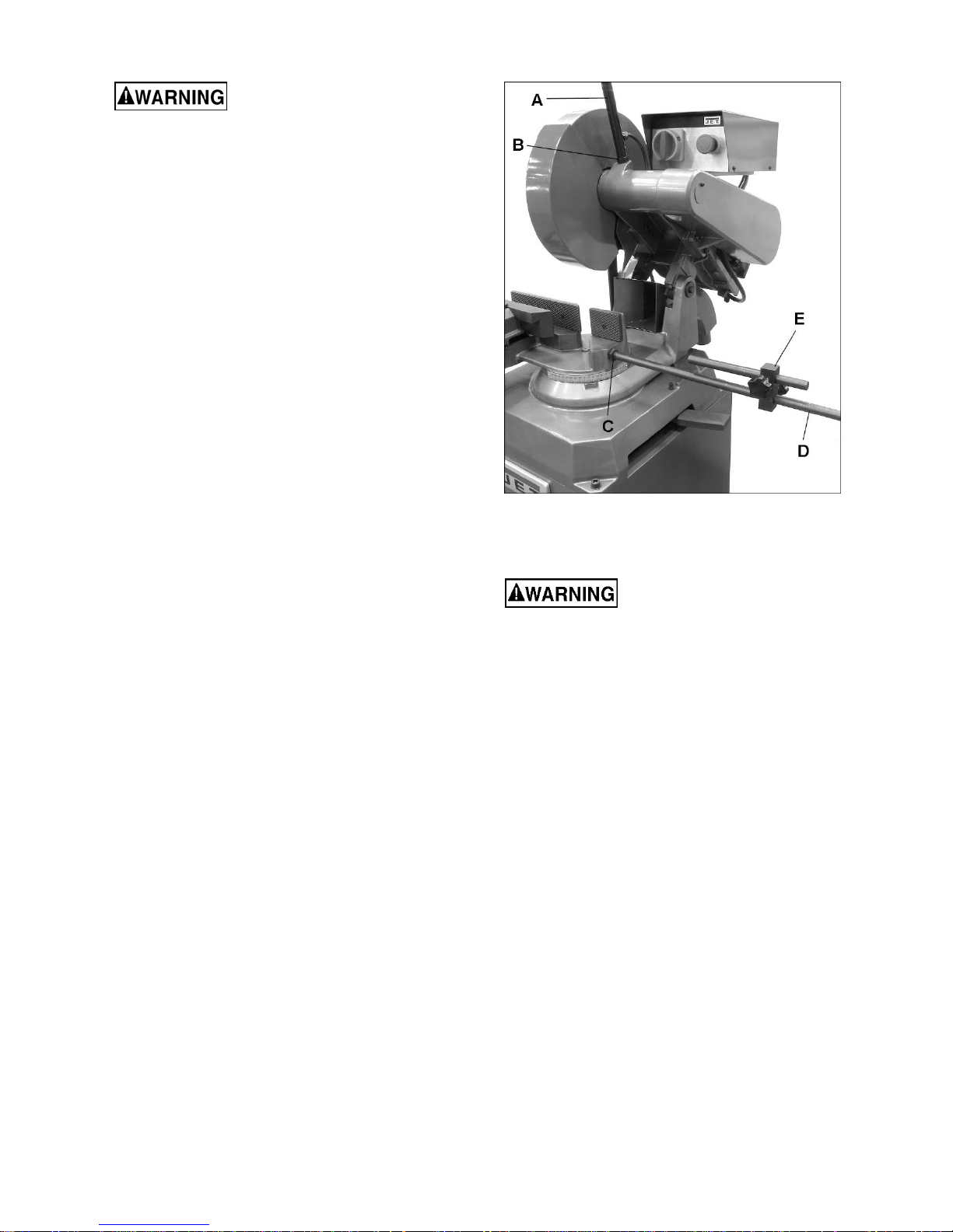
5.5 Operating handle
Refer to Figure 5-1.
1. Install operating handle (A) into threaded hole.
Rotate it a good distance into hole, and make
sure final orientation of handle grip is in
comfortable position for operator.
2. Secure operating handle by tightening hex nut
(B) against saw head.
Figure 5-1 (AB-12 shown)
6.0 Electrical connections
Electrical connections must
be made by a qualified
electrician in compliance with all relevant codes.
This machine must be properly grounded to
help prevent electrical shock and possible fatal
injury.
The AB-12 and AB-14 Abrasive Saws are rated for
3-phase, 230/460-volt power, prewired 230V. They
are not supplied with a plug. You may either install
a proper 230V UL/CSA listed plug, or “hardwire” the
machine directly to a service panel. To convert to
460-volt, see sect. 6.3.
Before connecting to power source, be sure switch
is in off position.
It is recommended that the, when used with 230V
power, be connected to a dedicated 20 amp circuit
with circuit breaker or time-delay fuse marked “D”.
When used with 460V power, connect the AB-14 to
a dedicated 10 amp circuit with circuit breaker or
time-delay fuse marked “D”.
NOTE: Local codes take precedence over
recommendations.
5.6 Material stop
Refer to Figure 5-1.
Screw lower rod (D) into threaded hole in base and
tighten hex nut (C) against base.
Install stop block with knobs (E) and upper rod as
shown.
6.1 GROUNDING INSTRUCTIONS
This machine must be grounded. In the event of a
malfunction or breakdown, grounding provides a
path of least resistance for electric current to reduce
the risk of electric shock.
If used with a plug:
8

Grounded, cord-connected tools intended for use on
a supply circuit having a nominal rating between
150-250 V inclusive:
This tool is intended for use on a three-phase circuit.
Make sure the tool is connected to an outlet having
the same configuration as the plug (not provided).
No adapter is available or should be used with this
tool. If the tool must be reconnected for use on a
different type of electric circuit, the reconnection
should be made by qualified service personnel; and
after reconnection, the tool should comply with all
local codes and ordinances.
If hardwired:
6.3 Conversion to 460V
The Abrasive Saw is prewired for 230 volt. To
change incoming leads for 460 volt operation:
1. Open main motor junction box cover, and
change leads based on wiring diagram inside
cover. Reinstall cover.
2. Reconnect wire on transformer from 230V
terminal to 460V terminal.
3. If using an electrical plug, replace current plug
with a UL/CSA listed plug rated for 460 volt
operation.
Permanently connected tools: This tool should be
connected to a grounded metal permanent wiring
system; or to a system having an equipmentgrounding conductor.
Improper connection of the
equipment-grounding conductor can r esult in a
risk of electric shock. Check with a qualified
electrician or service person if you are in do ubt
as to whether the outlet is properly grounded.
The conductor with insulation having an outer
surface that is green with or without yellow stripes is
the equipment-grounding conductor. If repair or
replacement of the electric cord or plug is
necessary, do not connect the equipment-grounding
conductor to a live terminal.
After wiring, make sure that the blade rotates in the
proper direction. If it does not, reverse two of the 3-
phase wires on the supply input.
6.2 Extension cords
The use of extension cords is discouraged; try to
position machines near the power source. If an
extension cord is necessary, make sure it is in good
condition. When using an extension cord, be sure to
use one heavy enough to carry the current your
product will draw. An undersized cord will cause a
drop in line voltage resulting in loss of power and
overheating.
Table 2 shows correct size to use depending on
cord length and nameplate ampere rating. If in
doubt, use the next heavier gauge. The smaller the
gauge number, the heavier the cord.
Ampere
Rating
More
Than
00 06 18 16 16 14
06 10 18 16 14 12
10 12 16 16 14 12
12 16 14 12
Not
More
Than
Table 2: Extension cord recommendations
Volts
240 50 100 200 300
AWG
Total length of
cord in feet
Not
Recommended
7.0 Adjustments
7.1 Miter adjustment
Refer to Figure 7-1.
The table has a rotational range of 90-degrees. To
adjust miter position, proceed as follows:
1. Move lock lever (F, Figure 7-1) toward the front
to release.
2. Push vise/table unit to desired angle, as shown
on scale. (On the AB-14 pull the stop knob out
to rotate vise unit. The knob will engage at +/45 and 90 degrees.)
3. Loosen handle (G) atop vise, and slide jaw as
needed to accommodate blade angle. Position
vise jaw as close as possible to blade.
Retighten handle securely.
4. When desired cutting angle is set, firmly move
lock lever rearward to secure setting.
Figure 7-1 (AB-12 shown)
9

7.2 Vise action
7.2.1 AB-12 vise
The AB-12 vise is self-centering and has a cam
action lever for fast clamping. Turn handwheel (H,
Figure 7-1) to move vise jaw about 1/16-inch away
from work piece, then rotate cam lever (J)
counterclockwise to tighten.
7.2.2 AB-14 vise
The AB-14 vise is self-centering, with double vise
jaws driven by a lead screw. Clamp work piece by
rotating vise handle.
4. Grasp blade with a gloved hand, and loosen
hex nut on spindle with provided wrench.
NOTE: Left-hand threads – turn clockwise to
loosen.
5. Remove nut, outer flange and blade. Clean
spindle and flange.
6. Install new blade, making sure that blade is flat
against inner flange, and orientation matches
any directional arrow printed on blade.
7. Tighten nut securely (counterclockwise), and
reconnect guard linkage.
7.5 Belt tension and replacement
7.3 Depth of cut adjustment
See Figure 7-2.
The front stop screw (K, Figure 7-2) limits blade
depth of cut. The rear stop screw (L) limits return
motion of head. These stops have been set by the
manufacturer. If future adjustment is needed:
To adjust depth of cut:
1. Disconnect machine from power source.
2. Loosen hex nut on stop screw, and lower head
all the way for front stop adjustment.
3. Turn screw with wrench until blade bottoms out
at desired level.
4. Tighten hex nut.
Raise head all the way for rear stop adjustment,
using similar procedure as above.
To replace the belts:
1. Remove belt cover.
2. Slightly loosen two screws (P, Figure 7-2) and
slide motor forward to de-tension belts.
3. Replace both belts as a set.
4. Slide motor back and tighten screws (P).
5. Belt tension can be adjusted by loosening hex
nut on tension screw (M, Figure 7-2) and turning
tension screw which moves the motor mount
slide plate.
6. Lock tension screw setting by tightening hex nut
against casting.
7. Reinstall belt cover.
8.0 Controls
Main switch (on control b ox) – Turns power on
and off.
Emergency Stop (on control box) – Press to shut
down machine. To restart machine, rotate button
clockwise to disengage E-stop.
Trigger (on operating han dle) – When pressed, it
activates micro-switch to start blade rotation.
Figure 7-2
7.4 Blade replacement
Disconnect machine from
power source before changing saw blades.
Failure to comply may result in serious injury!
1. Disconnect machine from power source.
2. Place saw head in fully raised position.
3. Remove screw (N, Figure 7-1) to release
linkage from blade guard, and rotate guard out
of the way.
9.0 Operation
1. Before using machine, check that safety
devices (e.g. blade guards) are in position and
work correctly and that personal safety
requirements are complied with.
2. Position work piece and close vise securely.
NOTE: Use supports, such as roller stands, for
long work pieces.
3. If mitering, adjust table accordingly and lock it
in position. If making a mitered cut, verify that
blade will not contact vise jaws; adjust if
needed.
4. If cutting multiple pieces to identical length,
adjust material stop and tighten in position.
5. Turn on main switch.
10

6. Start blade by pressing trigger on handle grip.
7. Pull down operating lever to bring blade into
work piece. You will manually control speed of
downstroke. Do not exert excessive pressure,
or damage to blade may result.
8. When cut is complete, release trigger and raise
head.
10.0 User-maintenance
10.1 Maintenance requirements
All maintenance and cleaning
procedures must be performed with the power
switched OFF. Failure to comply may result in
serious injury!
On completion of maintenance, ensure that
replaced parts and/or any tools used have been
removed from machine before starting it.
10.2 Periodic maintenance
Remove all swarf from machine, preferably
with a cloth or brush. Do not use bare hands.
Check blade wear and replace if necessary.
Clear chips away from vise/table area.
Clean vise and lubricate all joints and sliding
surfaces, using good quality oil. An oil fitting is
located atop the AB-12 vise near the cam
lever.
Grease vise leadscrew as needed.
Keep a light coat of oil on machined parts to
inhibit rust.
Inspect power cord. Repair or replace a
damaged or worn cord immediately.
10.3 Additional servicing
Any additional servicing should be performed by
authorized service personnel.
11

11.0 Troubleshooting AB-12/14 Abrasive Saws
11.1 Machine fault and operating problems
Symptom Possible Cause Correction*
Motor will not turn Low voltage. Check power line for proper voltage.
Open circuit in motor or loose
connection.
Emergency Stop engaged
Electrical power supply
Trigger switch not activating
Transformer
Magnetic Contactor
Thermal relay
Motor
Motor will not start:
fuses or circuit breakers
blow
Motor overheats Motor overloaded. Reduce load on motor.
Short circuit in line cord or plug. Inspect cord or plug for damaged insulation and
Short circuit in motor or loose
connections.
Incorrect fuses or circuit breakers
in power line.
Inspect all lead connections on motor for loose or
open connections.
Rotate Emergency Stop button to disengage.
Check: the phases; the cables; the plug; the socket.
Also check that the motor connections are in place.
Check that socket/plug connection from handle to
motor is inserted correctly; check micro-switch in
trigger.
Check that the voltages are present both on the
input and output. Otherwise replace.
Check that the phases in it are present both on the
input and output, that it is not jammed, that it closes
when powered and that it is not causing short
circuits. Change if any of these problems are found.
Make sure it is closed, i.e. check that the phases
are present in input and output, that it is not causing
short circuits and responds when the reset coil is
closed. If it has tripped to protect the motor, check
the amperage setting, re-set, and check the motor.
Change if necessary.
Check that it has not burned out, that it turns freely
and that there is no moisture in the connection
terminal board box. The winding can be rewound or
replaced by experienced motor repair personnel.
shorted wires.
Inspect all connections on motor for loose or
shorted terminals or worn insulation.
Install correct fuses or circuit breakers.
Air circulation through motor
restricted.
Motor stalls, resulting in
blown fuses or tripped
circuit
Machine slows when
operating
Loud, repetitive noise
coming from machine
Motor overloaded. Reduce load on motor.
Short circuit in motor or loose
connections.
Low voltage. Correct the low voltage conditions.
Incorrect fuses or circuit breakers
in power line.
Applying too much pressure. Feed blade into workpiece more slowly.
Belt loose. Tighten belt.
Floor uneven. Shim beneath stand to make level.
Pulley setscrews or keys are
missing or loose.
Motor fan is hitting the cover. Tighten fan or shim cover.
V-belt is defective. Replace V-belt.
*Warning: Some corrections may require a qualified electrician.
Table 3
12
Clean motor fan with compressed air to restore
normal air circulation.
Inspect connections on motor for loose or shorted
terminals or worn insulation.
Install correct fuses or circuit breakers.
Inspect keys and setscrews. Replace or tighten if
necessary.

11.2 Blade and cutting problems
Symptom Possible Cause Correction
Rapid blade wear Feed speed too slow The blade runs over the material without
removing it: Increase pressure of blade into
workpiece.
Broken blade
Cuts not straight
Feed speed too high
Blade in contact with material before
starting the cut
Feed speed too strong
Blade not perpendicular to workpiece.
Table 4
Reduce pressure of blade into workpiece.
Make sure blade is clear of workpiece before
starting machine.
Reduce feed speed.
Contact JET technical support.
12.0 Replacement Parts
Replacement parts are listed on the following pages. To order parts or reach our service department, call 1-800274-6848 Monday through Friday, 8:00 a.m. to 5:00 p.m. CST. Having the Model Number and Serial Number of
your machine available when you call will allow us to serve you quickly and accurately.
Non-proprietary parts, such as fasteners, can be found at local hardware stores, or may be ordered from JET.
Some parts are shown for reference only, and may not be available individually.
13

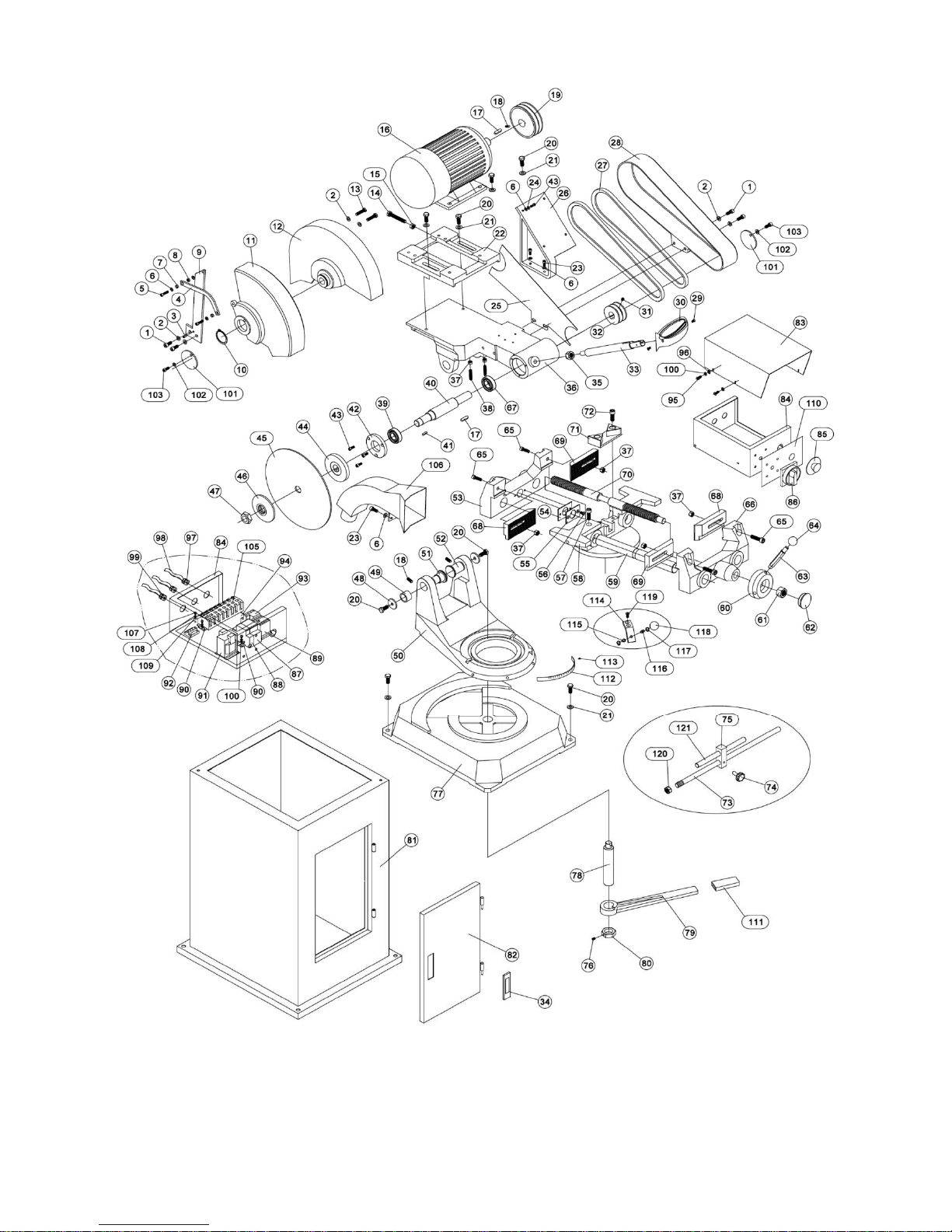
12.1.1 AB-12 Abrasive Saw – Exploded View
14

12.1.2 AB-12 Abrasive Saw – Parts List
Index No Part No Description Size Qty
1 ................ TS-1504041 .............. Socket Head Cap Screw ......................................... M8x20 ........................... 4
2 ................ TS-1550061 .............. Flat Washer ............................................................. 8mm .............................. 6
3 ................ AB12-03 .................... Spring Pin ................................................................ 6x12mm ....................... 1
4 ................ AB12-04 .................... Pull Rod ................................................................... ...................................... 1
5 ................ TS-1503061 .............. Socket Head Cap Screw ......................................... M6x25 ........................... 2
6 ................ TS-1550041 ............. Flat Washer ............................................................. 6mm ............................ 12
7 ................ AB12-07 .................... Ring ......................................................................... ...................................... 2
8 ................ TS-2311061 .............. Hex Nut .................................................................... M6 ................................. 1
9 ................ AB12-09 .................... Plate......................................................................... ...................................... 1
10 .............. F006056 .................... Ext. Retaining Ring .................................................. 45 mm ........................... 1
11 .............. AB12-11 .................... Blade Guard A ......................................................... ...................................... 1
12 .............. AB12-12 .................... Blade Guard B ......................................................... ...................................... 1
13 .............. TS-1490061 .............. Hex Cap Screw ........................................................ M8x35 ........................... 2
14 .............. TS-1491121 .............. Hex Cap Screw ........................................................ M10x70 ......................... 1
15 .............. TS-2311101 .............. Hex Nut .................................................................... M10 ............................... 1
16 .............. AB12-16-230 ............. Motor (for s/n 16110001~16110009) ....................... 5HP 230V 3PH ............. 1
.................. AB12-16-230/460 ...... Motor (for s/n 16110010 and higher) ....................... 5HP 230/460 3PH ......... 1
.................. AB12-16-1 ................. Motor Fan Cover (not shown) .................................. ...................................... 1
.................. AB12-16-2 ................. Motor Fan (not shown)............................................. ...................................... 1
.................. AB12-16-3….. ........... Junction Box (not shown) ........................................ ...................................... 1
.................. AB12-16-4 ................. Junction Box Cover (not shown) .............................. ...................................... 1
17 .............. EPR1460-89-2 .......... Key, Double Rd Hd .................................................. 8x8x30mm .................... 2
18 .............. TS-1524031 .............. Socket Set Screw .................................................... M8x12 ........................... 3
19 .............. AB12-19 .................... Motor Pulley ............................................................. ...................................... 1
20 .............. TS-1491031 .............. Hex Cap Screw ........................................................ M10x25 ....................... 10
21 .............. TS-1550071 .............. Flat Washer ............................................................. 10mm ............................ 8
22 .............. AB12-22 .................... Motor Base .............................................................. ...................................... 1
23 .............. TS-1503031 .............. Socket Head Cap Screw ......................................... M6x12 ........................... 2
24 .............. TS-2361061 .............. Lock Washer ............................................................ 6mm .............................. 4
25 .............. AB12-25 .................... Baffle........................................................................ ...................................... 1
26 .............. AB12-26 .................... Electrical Box Mount ................................................ ...................................... 1
27 .............. VB-A940 .................... Belt........................................................................... A940 ............................. 2
28 .............. AB12-28 .................... Belt guard ................................................................ ...................................... 1
29 .............. TS-1533032 .............. Machine Screw, Pan Head ...................................... M5x10 ........................... 2
30 .............. AB12-30 .................... Switch Handle .......................................................... ...................................... 1
31 .............. TS-1524051 .............. Socket Set Screw......................................................M8x20...........................3
32 .............. AB12-32 .................... Spindle Pulley .......................................................... ...................................... 1
33 .............. AB12-33 .................... Handle Shank .......................................................... ...................................... 1
34 .............. AB12-34 .................... Spring Lock Assembly ............................................. MS720-2 ....................... 1
35 .............. TS-2311141 .............. Hex Nut .................................................................... M14 ............................... 1
36 .............. AB12-36 .................... Brace ....................................................................... ...................................... 1
37 .............. TS-2311101 .............. Hex Nut .................................................................... M10 ............................... 6
38 .............. AB12-38 .................... Lock Bolt .................................................................. M8X40 .......................... 2
39 .............. BB-6206ZZ ................ Ball Bearing ............................................................. 6206-2Z ........................ 2
40 .............. AB12-40 .................... Spindle ..................................................................... ...................................... 1
41 .............. 5509207 .................... Key, Double Rd Hd .................................................. 5x5x20mm .................... 1
42 .............. AB12-42 .................... Cover ....................................................................... ...................................... 1
43 .............. TS-1482031 .............. Hex Cap Screw ........................................................ M6x16 ........................... 7
44 .............. AB12-44 .................... Inner Flange ............................................................ ...................................... 1
45 .............. AB12-45 .................... Blade........................................................................ Φ300 x Φ25.4x3 mm..... 1
46 .............. AB12-46 .................... Outer Flange ............................................................ ...................................... 1
47 .............. AB12-47 .................... Hex Nut .................................................................... ...................................... 1
48 .............. AB12-48 .................... Pad .......................................................................... ...................................... 2
49 .............. AB12-49 .................... Eccentric Sheath ..................................................... ...................................... 1
50 .............. AB12-50 .................... Rotary Arm............................................................... ...................................... 1
51 .............. AB12-51 .................... Eccentric Shaft......................................................... ...................................... 1
52 .............. AB12-52 .................... Shaft ........................................................................ ...................................... 1
53 .............. TS-1524011 .............. Socket Set Screw .................................................... M8x8 ............................. 1
54 .............. AB12-54 .................... Fixed Vise Assembly ............................................... ...................................... 1
55 .............. AB12-55 .................... Vise Plate................................................................. 2-3/8” x 8-3/4” ............... 1
15

Index No Part No Description Size Qty
56 .............. AB12-56 .................... Vise plate ................................................................. 2-3/8” x 3-1/8” ............... 1
57 .............. AB12-57 .................... Adjustable Handle ................................................... M10X30 ........................ 2
58 .............. TS-2361101 .............. Lock Washer ............................................................ 10mm ............................ 1
59 .............. AB12-59 .................... Washer .................................................................... ...................................... 1
60 .............. TS-1514021 .............. Flat Hd Socket Cap Screw....................................... M6x16 ........................... 3
61 .............. AB12-61 .................... Vise Plate................................................................. ...................................... 1
62 .............. AB12-62 .................... Upper Vise ............................................................... ...................................... 1
63 .............. AB12-63 .................... Adjust Plate ............................................................. ...................................... 1
64 .............. TS-1524061 .............. Socket Set Screw .................................................... M8X25 .......................... 4
65 .............. AB12-65 .................... Vise Leadscrew ....................................................... ...................................... 1
66 .............. AB12-66 .................... Spring ...................................................................... ...................................... 1
67 .............. BB-6205ZZ ................ Ball Bearing ............................................................. 6205-2Z ........................ 1
68 .............. AB12-68 .................... Oil Cup ..................................................................... M6 ................................. 1
69 .............. AB12-69 .................... Lock Ring ................................................................. ...................................... 1
70 .............. AB12-70 .................... Lock Handle ............................................................. ...................................... 1
71 .............. AB12-71 .................... Bearing .................................................................... AXK3047 ....................... 1
72 .............. AB12-72 .................... Bearing Cover .......................................................... ...................................... 1
73 .............. AB12-73 .................... Handwheel Assembly .............................................. Ø150Xø18 mm ............. 1
74 .............. AB12-74 .................... Washer .................................................................... ...................................... 1
75 .............. F010985 .................... Flat Hd Socket Cap Screw....................................... M8X35 .......................... 1
76 .............. TS-1523031 .............. Socket Set Screw .................................................... M6X10 .......................... 2
77 .............. AB12-77 .................... Base......................................................................... ...................................... 1
78 .............. AB12-78 .................... Shaft ........................................................................ ...................................... 1
79 .............. AB12-79 .................... Lock Handle ............................................................. ...................................... 1
80 .............. AB12-80 .................... Nut ........................................................................... ...................................... 1
81 .............. AB12-81 .................... Stand ....................................................................... ...................................... 1
82 .............. AB12-82 .................... Door ......................................................................... ...................................... 1
83 .............. AB12-83 .................... Cover ....................................................................... ...................................... 1
84 .............. AB12-84 .................... Electrical Box ........................................................... ...................................... 1
85 .............. AB12-85 .................... Emergency Switch ................................................... XB2-ES542 ................... 1
86 .............. AB12-86 .................... Main Switch ............................................................. SA1 ZH-DH-2 ................ 1
87 .............. AB12-87 .................... Circuit Breaker ......................................................... NB1-63 2P2A ................ 1
88 .............. AB12-88 .................... Circuit Breaker ......................................................... NB1-63 1P1A ................ 1
89 .............. AB12-89 .................... A.C. Contactor. ........................................................ CU-18 AC24V ............... 1
90 .............. AB12-90 .................... Caliper Gauge ......................................................... ...................................... 2
91 .............. AB12-91-230V ........... Transformer (for s/n 16110001~16110009) ............. JCY-63 220/24V ........... 1
.................. AB12-91-230/460V .... Transformer (for s/n 16110010 and higher) ............. JCY-63 230/460/24V .... 1
92 .............. AB12-92 .................... Grounding Copper Bar ............................................ ...................................... 1
93 .............. AB12-93 .................... Thermal Relay ......................................................... RHU-10 6A 11.3-16A .... 1
94 .............. AB12-94 .................... Subplate .................................................................. ...................................... 1
95 .............. TS-2284082 .............. Machine Screw, Pan Head ...................................... M4x8 ........................... 12
96 .............. TS-1550021 .............. Flat Washer ............................................................. 4mm ............................ 12
97 .............. AB12-97 .................... Strain Relief ............................................................. M20x1.5 ........................ 2
98 .............. AB12-98 .................... Wire ......................................................................... 14AWG ......................... 3
99 .............. AB12-99 .................... Strain Relief ............................................................. M16x1.5 ........................ 1
100 ............ TS-2361041 .............. Lock Washer ............................................................ 4mm ............................ 12
101 ............ AB12-101 .................. Cover ....................................................................... ...................................... 2
102 ............ TS-1550021 .............. Flat Washer ............................................................. 4mm ......
........................ 2
103 ............ TS-1501021 .............. Socket Head Cap Screw ......................................... M4x8 ............................. 2
104 ............ F003068 .................... Hex Nut, Blk Oxd ..................................................... M4-0.7 ........................... 3
105 ............ AB12-105 .................. Terminal Block ......................................................... ...................................... 1
106 ............ AB12-106 .................. Spark Collector ........................................................ ...................................... 1
107 ............ TS-1533032 .............. Machine Screw, Pan Head ...................................... M5x10 ........................... 2
108 ............ TS-1550031 .............. Flat Washer ............................................................. 5mm .............................. 2
109 ............ TS-2361051 .............. Lock Washer ............................................................ 5mm .............................. 3
110 ............ AB12-110 .................. Control Panel ........................................................... ...................................... 1
111 ............ AB12-111 .................. Rubber Grip ............................................................. ...................................... 1
112 ............ AB12-112 .................. Scale ........................................................................ ...................................... 1
113 ............ AB12-113 .................. Rivet......................................................................... 2x6mm .......................... 2
114 ............ AB12-114 .................. Connecting Bar ........................................................ ...................................... 1
115 ............ AB12-115 .................. Star Grip Knob ......................................................... ...................................... 1
16

Index No Part No Description Size Qty
116 ............ AB12-116 .................. Stop Block................................................................ ...................................... 1
117 ............ AB12-117 .................. Stop Rod .................................................................. ...................................... 1
118 ............ TS-154010 ................ Hex Nut .................................................................... M16 ............................... 1
.................. JET-165 ..................... JET Logo (not shown) ............................................. 165X68mm ................... 1
.................. LM000272 ................. ID/Warning Label, AB-12 (not shown) ..................... ...................................... 1
.................. LM000273 ................. Motor Lab el, AB-12 (not shown) .............................. ...................................... 1
17
12.2.1 AB-14 Abrasive Saw – Exploded View
18

12.2.2 AB-14 Abrasive Saw – Parts List
Index No Part No Description Size Qty
1 ................ TS-1504041 .............. Socket Head Cap Screw ......................................... M8x20 ........................... 4
2 ................ TS-1550061 .............. Flat Washer ............................................................. 8mm .............................. 6
3 ................ AB12-03 .................... Spring pin ................................................................ 6x12 mm ....................... 1
4 ................ AB12-04 .................... Pull rod..................................................................... ...................................... 1
5 ................ TS-1503061 .............. Socket Head Cap Screw ......................................... M6x25 ........................... 2
6 ................ TS-1550041 ............. Flat Washer ............................................................. 6mm ............................ 12
7 ................ AB12-07 .................... Ring ......................................................................... ...................................... 2
8 ................ TS-2311061 .............. Hex Nut .................................................................... M6 ................................. 1
9 ................ AB12-09 .................... Plate......................................................................... ...................................... 1
10 .............. F006056 .................... Ext. Retaining Ring .................................................. 45 mm ........................... 1
11 .............. AB14-11 .................... Blade Guard A ......................................................... ...................................... 1
12 .............. AB14-12 .................... Blade Guard B ......................................................... ...................................... 1
13 .............. TS-1490061 .............. Hex Cap Screw ........................................................ M8x35 ........................... 2
14 .............. TS-1491121 .............. Hex Cap Screw ........................................................ M10x70 ......................... 1
15 .............. TS-2311101 .............. Hex Nut .................................................................... M10 ............................... 1
16 .............. AB12-16-230 ............. Motor (for s/n 16110001~16110009) ....................... 5HP 230V 3PH ............. 1
.................. AB12-16-230/460 ...... Motor (for s/n 16110010 and higher) ....................... 5HP 230/460 3PH ......... 1
.................. AB12-16-1 ................. Motor Fan Cover (not shown) .................................. ...................................... 1
.................. AB12-16-2 ................. Motor Fan (not shown)............................................. ...................................... 1
.................. AB12-16-3….. ........... Junction Box (not shown) ........................................ ...................................... 1
.................. AB12-16-4 ................. Junction Box Cover (not shown) .............................. ...................................... 1
17 .............. EPR1460-89-2 .......... Key, Double Rd Hd .................................................. 8x8x30mm .................... 2
18 .............. TS-1524031 .............. Socket Set Screw .................................................... M8x12 ........................... 3
19 .............. AB12-10 .................... Motor Pulley ............................................................. ...................................... 1
20 .............. TS-1491031 .............. Hex Cap Screw ........................................................ M10x25 ....................... 10
21 .............. TS-1550071 .............. Flat Washer ............................................................. 10mm ............................ 8
22 .............. AB12-22 .................... Motor Base .............................................................. ...................................... 1
23 .............. TS-1503031 .............. Socket Head Cap Screw ......................................... M6x12 ........................... 2
24 .............. TS-2361061 .............. Lock Washer ............................................................ 6mm .............................. 4
25 .............. AB12-25 .................... Baffle........................................................................ ...................................... 1
26 .............. AB12-26 .................... Electrical Box Mount ................................................ ...................................... 1
27 .............. VB-A940 .................... Belt........................................................................... A940 ............................. 2
28 .............. AB12-28 .................... Belt Guard................................................................ ...................................... 1
29 .............. TS-1533032 .............. Machine Screw, Pan Head ...................................... M5x10 ........................... 2
30 .............. AB12-30 .................... Switch Handle .......................................................... ...................................... 1
31 .............. TS-1524051 .............. Socket Set Screw......................................................M8x20...........................3
32 .............. AB12-32 .................... Spindle Pulley .......................................................... ...................................... 1
33 .............. AB12-33 .................... Handle Shank .......................................................... ...................................... 1
34 .............. AB12-34 .................... Spring Lock Assembly ............................................. MS720-2 ....................... 1
35 .............. TS-2311141 .............. Hex Nut .................................................................... M14 ............................... 1
36 .............. AB12-36 .................... Brace ....................................................................... ...................................... 1
37 .............. TS-2311101 .............. Hex Nut .................................................................... M10 ............................... 2
38 .............. AB12-38 .................... Lock Bolt .................................................................. M8X40 .......................... 2
39 .............. BB-6206ZZ ................ Ball Bearing ............................................................. 6206-2Z ........................ 2
40 .............. AB12-40 .................... Spindle ..................................................................... ...................................... 1
41 .............. 5509207 .................... Key, Double Rd Hd .................................................. 5x5x20mm .................... 1
42 .............. AB12-42 .................... Cover ....................................................................... ...................................... 1
43 .............. TS-1482031 .............. Hex Cap Screw ........................................................ M6x16 .......................... 4
44 .............. AB12-44 .................... Inner Flange ............................................................ ...................................... 1
45 .............. AB14-45 .................... Blade........................................................................ Φ350 x ø25.4x3 mm ..... 1
46 .............. AB12-46 .................... Outer Flange ............................................................ ...................................... 1
47 .............. AB12-47 .................... Hex Nut .................................................................... ...................................... 1
48 .............. AB12-48 .................... Pad .......................................................................... ...................................... 2
49 .............. AB12-49 .................... Eccentric Sheath ..................................................... ...................................... 1
50 .............. AB14-50 .................... Rotary Arm............................................................... ...................................... 1
51 .............. AB12-51 .................... Eccentric Shaft......................................................... ...................................... 1
52 .............. AB12-52 .................... Shaft ........................................................................ ...................................... 1
53 .............. AB14-53 .................... Rear Clamping Body................................................ ...................................... 1
54 .............. AB14-54 .................... Rubber Pad ............................................................. ...................................... 2
55 .............. AB14-55 .................... Press Plate .............................................................. ...................................... 2
19

Index No. Part No. Description Size Qty
56 .............. TS-1534052 .............. Machine Screw, Pan Head ...................................... M6x16 ........................... 4
57 .............. TS-1505011 .............. Socket Head Cap Screw ......................................... M10X16 ........................ 1
58 .............. AB14-58 .................... Support Saddle ........................................................ ...................................... 1
59 .............. AB14-59 .................... Guiding Shaft ........................................................... ...................................... 2
60 .............. AB14-60 .................... Handle Seat ............................................................. ...................................... 1
61 .............. AB14-61 .................... Hex Nut .................................................................... M20x2 ........................... 1
62 .............. AB14-62 .................... Cap .......................................................................... ...................................... 1
63 .............. AB14-63 .................... Handle Lever ........................................................... ...................................... 3
64 .............. AB14-64 .................... Handle Ball .............................................................. ...................................... 3
65 .............. TS-1505061 .............. Socket Head Cap Screw ......................................... M10x40 ......................... 4
66 .............. AB14-66 .................... Front Clamping Body ............................................... ...................................... 1
67 .............. BB-6205ZZ ................ Ball Bearing ............................................................. 6205-2Z ........................ 1
68 .............. AB14-68 .................... Vise Plate................................................................. ...................................... 2
69 .............. AB14-69 .................... Vise Plate................................................................. ...................................... 2
70 .............. AB14-70 .................... Vise Leadscrew ....................................................... ...................................... 1
71 .............. AB14-71 .................... Positioning Block ..................................................... ...................................... 1
72 .............. TS-1505041 .............. Socket Head Cap Screw ......................................... M10x30 ......................... 1
73 .............. AB12-114 .................. Connecting Bar ........................................................ ...................................... 1
74 .............. AB12-115 .................. Star Grip Knob ......................................................... ...................................... 1
75 .............. AB12-116 .................. Stop Block................................................................ ...................................... 1
76 .............. TS-1523031 .............. Socket Set Screw .................................................... M6x10 ........................... 1
77 .............. AB14-77 .................... Base......................................................................... ...................................... 1
78 .............. AB14-78 .................... Shaft ........................................................................ ...................................... 1
79 .............. AB12-79 .................... Lock Handle ............................................................. ...................................... 1
80 .............. AB12-80 .................... Nut ........................................................................... ...................................... 1
81 .............. AB12-81 .................... Stand ....................................................................... ...................................... 1
82 .............. AB12-82 .................... Door ......................................................................... ...................................... 1
83 .............. AB12-83 .................... Cover...................................................................................... ........................ 1
84 .............. AB12-84 .................... Electrical Box ........................................................... ...................................... 1
85 .............. AB12-85 .................... Emergency Switch ................................................... XB2-ES542 ................... 1
86 .............. AB12-86 .................... Main Switch ............................................................. SA1 ZH-DH-2 ................ 1
87 .............. AB12-87 .................... Circuit Breaker ......................................................... NB1-63 2P2A ................ 1
88 .............. AB12-88 .................... Circuit Breaker ......................................................... NB1-63 1P1A ................ 1
89 .............. AB12-89 .................... A.C. Contactor. ........................................................ CU-18 AC24V ............... 1
90 .............. AB12-90 .................... Caliper Gauge ......................................................... ...................................... 2
91 .............. AB12-91-230V ........... Transformer (for s/n 16110001~16110009) ............. JCY-63 220/24V ........... 1
.................. AB12-91-230/460V .... Transformer (for s/n 16110010 and higher) ............. JCY-63 230/460/24V .... 1
92 .............. AB12-92 .................... Grounding Copper Bar ............................................ ...................................... 1
93 .............. AB12-93 .................... Thermal Relay ......................................................... RHU-10 6A 11.3-16A .... 1
94 .............. AB12-94 .................... Subplate .................................................................. ...................................... 1
95 .............. TS-2284082 .............. Machine Screw, Pan Head ...................................... M4x8 ........................... 12
96 .............. TS-1550021 .............. Flat Washer ............................................................. 4mm ............................ 12
97 .............. AB12-97 .................... Strain Relief ............................................................. M20x1.5 ........................ 2
98 .............. AB12-98 .................... Wire ......................................................................... 14AWG ......................... 3
99 .............. AB12-99 .................... Strain Relief ............................................................. M16x1.5 ........................ 1
100 ............ TS-2361041 .............. Lock Washer ............................................................ 4mm ............................ 12
101 ............ AB12-101 .................. Cover ....................................................................... ...................................... 2
102 ............ TS-1550021 .............. Flat Washer ............................................................. 4mm ......
103 ............ TS-1501021 .............. Socket Head Cap Screw ......................................... M4x8 ............................. 2
105 ............ AB12-105 .................. Terminal Block ......................................................... ...................................... 1
106 ............ AB14-106 .................. Spark Collector ........................................................ ...................................... 1
107 ............ TS-1533032 .............. Machine Screw, Pan Head ...................................... M5x10 ........................... 2
108 ............ TS-1550031 .............. Flat Washer ............................................................. 5mm .............................. 2
109 ............ TS-2361051 .............. Lock Washer ............................................................ 5mm .............................. 3
110 ............ AB12-110 .................. Control Panel ........................................................... ...................................... 1
111 ............ AB12-111 .................. Rubber Grip ............................................................. ...................................... 1
112 ............ AB14-112 .................. Scale ........................................................................ ...................................... 1
113 ............ AB12-113 .................. Rivet......................................................................... 2x6mm .......................... 2
114 ............ AB14-114 .................. Connecting Plate ..................................................... ...................................... 1
115 ............ AB14-115 .................. Spring ...................................................................... ...................................... 1
116 ............ AB14-116 .................. Pin Shaft .................................................................. ...................................... 1
117 ............ F006039 .................... Ext. C-Ring .............................................................. 8mm .............................. 2
........................ 2
20

Index No. Part No. Description Size Qty
118 ............ AB14-118 .................. Handle Ball .............................................................. M8 ................................. 1
119 ............ TS-1514021 .............. Socket Head Flat Screw .......................................... M6x16 ........................... 2
120 ............ TS-154010 ................ Hex Nut .................................................................... M16 ............................... 1
121 ............ AB12-117 .................. Stop Rod .................................................................. ...................................... 1
.................. JET-165 ..................... JET Logo (not shown) ............................................. 165x68 mm ................... 1
.................. LM000274 ................. ID/Warning Label, AB-14 (not shown) ..................... ...................................... 1
.................. LM000275 ................. Motor Lab el, AB-14 (not shown) .............................. ...................................... 1
21

13.0 Electrical Connections for AB-12,AB-14
22

14.0 Warranty and service
JET warrants every product it sells against manufacturers’ defects. If one of our tools needs service or repair, please
contact Technical Service by calling 1-800-274-6846, 8AM to 5PM CST, Monday through Friday.
Warranty Period
The general warranty lasts for the time period specified in the literature included with your product or on the official
JET branded website.
• JET products carry a limited warranty which varies in duration based upon the product. (See chart below)
• Accessories carry a limited warranty of one year from the date of receipt.
• Consumable items are defined as expendable parts or accessories expected to become inoperable within a
reasonable amount of use and are covered by a 90 day limited warranty against manufacturer’s defects.
Who is Covered
This warranty covers only the initial purchaser of the product from the date of delivery.
What is Covered
This warranty covers any defects in workmanship or materials subject to the limitations stated below. This warranty
does not cover failures due directly or indirectly to misuse, abuse, negligence or accidents, normal wear-and-tear,
improper repair, alterations or lack of maintenance. JET woodworking machinery is designed to be used with Wood.
Use of these machines in the processing of metal, plastics, or other materials outside recommended guidelines may
void the warranty. The exceptions are acrylics and other natural items that are made specifically for wood turning.
Warranty Limitations
Woodworking products with a Five Year Warranty that are used for commercial or industrial purposes default to a
Two Year Warranty. Please contact Technical Service at 1-800-274-6846 for further clarification.
How to Get Technical Support
Please contact Technical Service by calling 1-800-274-6846. Please note that you will be asked to provide proof
of initial purchase when calling. If a product requires further inspection, the Technical Service representative will
explain and assist with any additional action needed. JET has Authorized Service Centers located throughout the
United States. For the name of an Authorized Service Center in your area call 1-800-274-6846 or use the Service
Center Locator on the JET website.
More Information
JET is constantly adding new products. For complete, up-to-date product information, check with your local distributor
or visit the JET website.
How State Law Applies
This warranty gives you specific legal rights, subject to applicable state law.
Limitations on This Warranty
JET LIMITS ALL IMPLIED WARRANTIES TO THE PERIOD OF THE LIMITED WARRANTY FOR EACH PRODUCT.
EXCEPT AS STATED HEREIN, ANY IMPLIED WARRANTIES OF MERCHANTABILITY AND FITNESS FOR A
PARTICULAR PURPOSE ARE EXCLUDED. SOME STATES DO NOT ALLOW LIMITATIONS ON HOW LONG AN
IMPLIED WARRANTY LASTS, SO THE ABOVE LIMITATION MAY NOT APPLY TO YOU.
JET SHALL IN NO EVENT BE LIABLE FOR DEATH, INJURIES TO PERSONS OR PROPERTY, OR FOR
INCIDENTAL, CONTINGENT, SPECIAL, OR CONSEQUENTIAL DAMAGES ARISING FROM THE USE OF OUR
PRODUCTS. SOME STATES DO NOT ALLOW THE EXCLUSION OR LIMITATION OF INCIDENTAL OR
CONSEQUENTIAL DAMAGES, SO THE ABOVE LIMITATION OR EXCLUSION MAY NOT APPLY TO YOU.
JET sells through distributors only. The specifications listed in JET printed materials and on official JET website are
given as general information and are not binding. JET reserves the right to effect at any time, without prior notice,
those alterations to parts, fittings, and accessory equipment which they may deem necessary for any reason
whatsoever. JET
Product Listing with Warranty Period
90 Days – Parts; Consumable items
1 Year – Motors; Machine Accessories
2 Year – Metalworking Machinery; Electric Hoists, Electric Hoist Accessories; Woodworking Machinery used
for industrial or commercial purposes
5 Year – Woodworking Machinery
Limited Lifetime – JET Parallel clamps; VOLT Series Electric Hoists; Manual Hoists; Manual Hoist
Accessories; Shop Tools; Warehouse & Dock products; Hand Tools; Air Tools
NOTE: JET is a division of JPW Industries, Inc. References in this document to JET also apply to JPW Industries,
Inc., or any of its successors in interest to the JET brand.
®
branded products are not sold in Canada by JPW Industries, Inc.
23

427 New Sanford Road
LaVergne, Tennessee 37086
Phone: 800-274-6848
www.jettools.com
24
 Loading...