

Page 1
This .pdf document is bookmarked
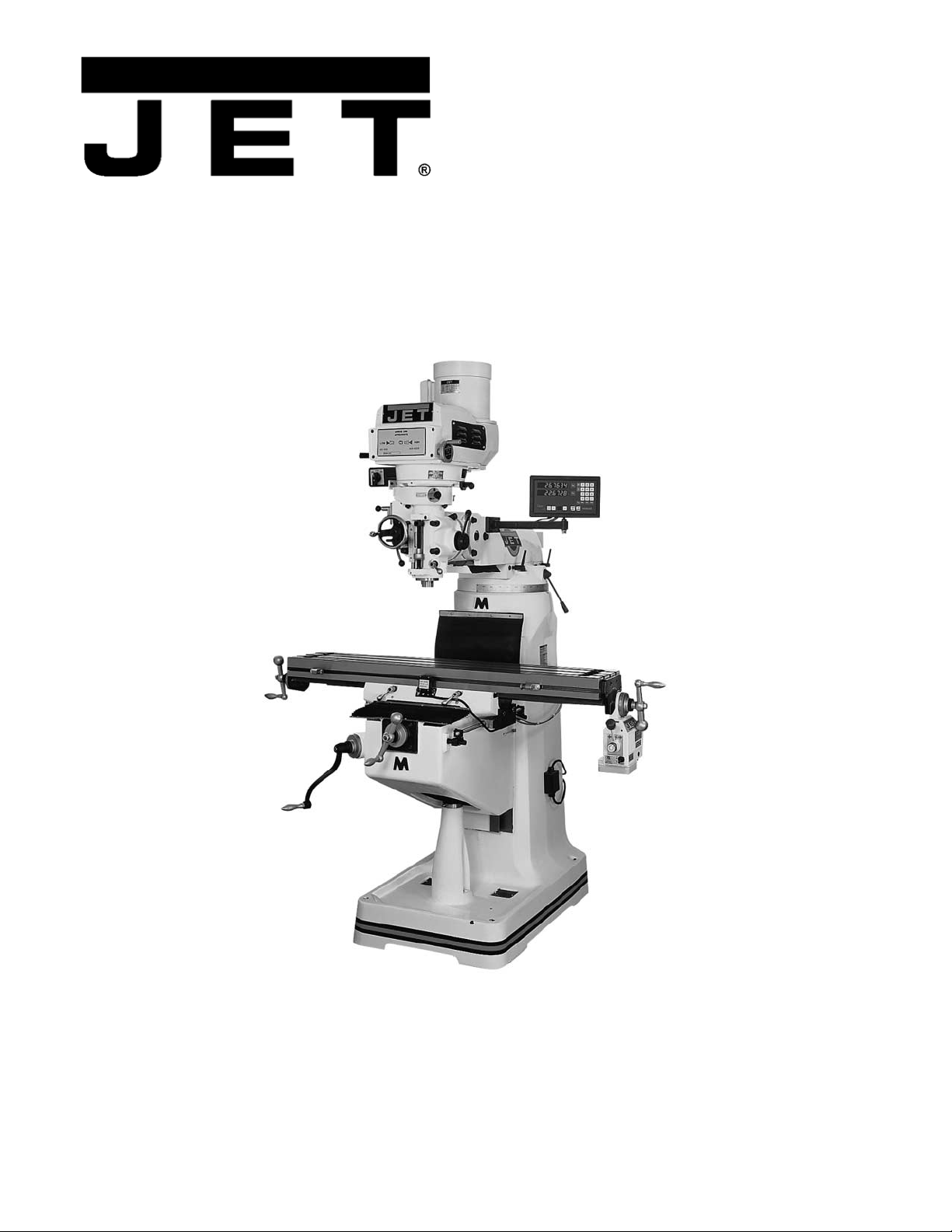
Operating Instructions and Parts Manual
Variab le Speed Tu rret Mill
Model JTM-4VS
Shown with optional accessori es X- Axis Tabl e Powerfeed and DRO
WALTER MEIER (Manuf acturing) Inc.
427 New Sanford Road
LaVergne, Tennessee 37086 Part No. M- 690182
Ph.: 800-274-6848 Revision G 06/ 2010
www.walt er meier.c om Copyright © 2010 Walt er Meier (M anufacturi ng) Inc.
Page 2
W arranty and Service
W alter Meier (Manufacturin g) Inc ., warr ants every product it sel ls. If on e of our tools needs ser vice or r epair, one of our Authorized
Service Centers located throughout the United States can gi ve you quick ser vice. In mos t cases, any of these W alter Meier
Authorized Service Centers can authorize warranty repai r, assist you i n obtaining part s, or per for m r outin e maintenanc e and ma jor
repai r on your JET® tools. For the name of an Authorized Service Center in your area cal l 1- 800-274-6848.
MORE INFORMATION
W alter M eier is c onsi st en tly addi ng n e w products to th e li ne. For c o mplet e, up-to- da te pr oduc t i nf or mati on, c hec k wi th y our loc al
W alter Meier distribu tor , or vi sit wa lter meier.c om.
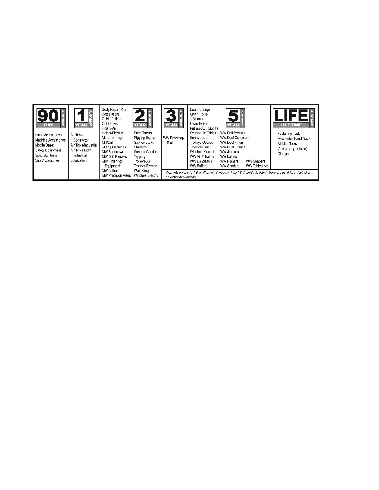
WARRANTY
JET products carry a limited warranty which varies in duration based upon the product (MW = Metalworking, WW =
Woodworking).
WHAT IS COV ERED?
This warranty covers any defec ts in workmanship or materials subject to the exceptions stated below. Cutting tools, abrasives and
other consumables are e xcluded from warranty coverage.
WHO IS COVERED?
This w arranty covers only the initial purcha ser of t he product.
WHAT IS THE PERIOD O F COVERAGE?
The general JET warranty lasts for the time per iod specified in the product li terature of each pro duct.
WHAT IS NOT COVERED?
Five Year Warranties do not cover woodworking (WW) products used for commercial, industrial or educational purposes.
W oodworking pr oduc t s wit h Fi ve Ye ar W arr anties th at ar e us ed for co mmer ci a l, indu str ia l or e duc a tion purp os es re ver t to a One
Year W ar r anty. This warra nty do es no t c over def ec ts d ue dir ec tly or i ndir ec tly to misu se, a buse, ne gli genc e or ac ci dents, nor mal
wear-and- tear, improper r epair or alteration s, or lack of mainten ance.
HOW TO G ET SERVICE
The pr oduc t or part must be re turned f or exami nation, po stage pre paid, to a loca tion d esigna ted by us. For the n ame of the
location neares t you, p lease call 1-800-2 74-6848.
You m ust pr ovide pr oof of ini tial p urchas e dat e and an e xpl anati on of th e co mp lain t must ac co mpany t he merc handi se. If our
insp ec tio n disc los es a defec t, we will r epai r or r eplace t he pr oduc t, or r efun d th e purc ha se pri c e, at o ur opti on. W e wil l retu rn the
repai red pr oduc t or r ep lace men t at our e xpen se un les s it i s d et er mine d by us th at t here is n o d efec t, or that the def ec t r esu lt ed
fr om cau ses no t withi n the sc op e of our warran ty i n which c ase we will, at y our di r ecti on, di spos e of or r eturn th e pro duc t. I n the
event you c hoose to have t he product returned, you will be responsib le for the shipping and handling costs of the ret urn.
HOW STATE LAW APPLIES
This warranty gi ves you specific legal ri ghts; y ou may a lso have other rights which vary from sta te to sta te.
LIMITATIONS ON THIS WARRANTY
WALTER MEIER (MANUFACTURING) INC., LIMITS ALL IMPLIED WARRANTIES TO THE PERIOD OF THE LIMITED
WARRANTY FOR EACH PRODUCT. EXCEPT AS STATED HEREIN, ANY IMPLIED WARRANTIES OR MERCHANTABILITY
AND FI TNESS ARE EXCL UDED. SOME STA TES DO NOT ALL OW LIMI TATIONS ON HOW LONG THE IMPLIE D WA RRANTY
LASTS, SO THE ABOVE LIMI TATION MAY NOT APPLY TO YOU.
WALTER MEIER SHALL IN NO EVENT BE LIABLE FOR DEATH, INJURIES TO PERSONS OR PROPERTY, OR FOR
INCIDE NTAL, CONTI NGENT, S PECIAL, OR CONSE QUENTIAL DA MAGES A RI SING FROM THE USE OF OUR PRODUC TS.
SOME STA TES DO NOT ALL OW THE EXCLUSI O N OR LIMITA TION OF I NCIDE NTAL OR CONS E QUENTIA L DAMAGES, S O
THE ABOVE LIMI TATI ON OR EXCLUSI ON MAY NOT AP PLY TO YOU.
W alter Meier se lls t hrou gh dis tr ibu tor s on ly. The s peci fi c ation s in W alt er Mei er c atalo gs are give n as gen er al inf or mati on a nd are
not bi nding. Me mb ers of Walter Meier reserve the right to effect at any time, withou t prior noti ce, th ose alt erations to part s, fittings,
and ac c essor y eq uip men t w hic h they may d ee m n ecess ar y f or any r e ason wh at so ever . J E T® br ande d pr oduc ts are no t so l d in
Canada by Walter Meier.
2
Page 3

Ta ble of Contents
Warranty and Service .................................................................................................................................2
In trodu c tion ...............................................................................................................................................7
Spe ci fic ati ons ............................................................................................................................................7
Unpacking .................................................................................................................................................8
Contents of the Shipping Container..........................................................................................................8
Set-up and Installation................................................................................................................................9
Prepari ng the Milling Machine for Service.................................................................................................9
JTM-4VS Dimensions............................................................................................................................... 10
JTM-4VS Overview and Terminology ........................................................................................................ 11
Electrical Connect io ns .............................................................................................................................. 12
General Electrical Cautions ................................................................................................................ 12
Wire Sizes ........................................................................................................................................ 12
Lu bricati on ........................................................................................................................................... 12
Operating Instructions .............................................................................................................................. 12
Operating Controls ............................................................................................................................... 12
Motor Sw itch ........................................................................................................................................ 12
Variable Speed Control ......................................................................................................................... 13
Spindle Brake....................................................................................................................................... 14
High-Neutral-Low Shift Lever................................................................................................................. 14
Quill Power Feed Lever......................................................................................................................... 14
Feed Rate Lever................................................................................................................................... 14
Feed Trip Cam Lever ............................................................................................................................ 15
Feed Direction Control .......................................................................................................................... 15
Coarse Feed Handle ............................................................................................................................. 15
Quill Lock Lever.................................................................................................................................... 15
Micrometer Adjusting Nut ...................................................................................................................... 15
Fine Feed Handwhee l ........................................................................................................................... 15
Depth Scale and Stop ........................................................................................................................... 16
Power Feed O per at ion .......................................................................................................................... 16
Draw Bar Operation - Changing Tooling ................................................................................................. 17
Clamping Work Piece to the Table ......................................................................................................... 17
Adjustmen ts ............................................................................................................................................ 17
Mill Head – Left/Right Adjustment .......................................................................................................... 17
Mill Head – Fore/Aft Adjustment ............................................................................................................ 18
Positioning the Ram.............................................................................................................................. 19
Positioni ng the Ram Fore and Aft ....................................................................................................... 19
Positioning the Ram on its Turret........................................................................................................ 19
Gib Adjustment..................................................................................................................................... 19
Adjustment of Knee Gib ..................................................................................................................... 19
Adjustment of Saddle Gib .................................................................................................................. 19
Adjustment of Table Gib .................................................................................................................... 19
Power Feed Tr ip Lever Mechanism ........................................................................................................ 20
Table Lead Screw Backlas h Adjust me nt ................................................................................................ 20
Cross Feed Backlash Adjustment ....................................................................................................... 20
Longitudinal Backlash Adjustment ...................................................................................................... 20
Maintenance............................................................................................................................................ 22
Lu bricati on ........................................................................................................................................... 22
Periodic Maintenance Requirements .................................................................................................. 22
Replacement of Drive Motor .................................................................................................................. 23
Replacement of Vari- Speed Belt ............................................................................................................ 24
Replacement of Brake Shoes, Springs and/or Timing Belt ....................................................................... 24
Replacement of Q uill Feed Clock Spring ................................................................................................ 25
Replacement Parts .................................................................................................................................. 25
Head Assembly .................................................................................................................................... 26
Parts List for Head Assembly ................................................................................................................ 27
Spindle Assembly ................................................................................................................................. 30
Base Assembly .................................................................................................................................... 34
Parts List for Base Assembly ................................................................................................................. 35
3
Page 4

Lead Screw Assembly .......................................................................................................................... 37
One-Shot Lubrication System ................................................................................................................ 38
Electrical Connect io ns – Single Phase only ............................................................................................ 39
Electrical Connect io ns – 3 Phase only ................................................................................................... 40
4
Page 5

Warning
1. Read and understand t he entire owner’s manual befor e attempting assembly or operation.
2. Read and understand the war ni ngs posted on the machine and in this manual. Failure to c omp ly w ith all of
these warnings may cause serio us injury.
3. Replace the warning labels if they become obscured or removed.
4. This turret mill is designed and intended for use by properly trai ned and experi enced personnel only. If you
are not f amiliar with the pr oper and safe oper ation of a turret mill, do not use unt il proper tr aining and
knowledge have bee n obtai ned.
5. Do not use this turret mill for other t han its i ntended use. I f used for other purposes, W MH Tool Group
disclaims any r eal or implied war ra nty and holds itself harmless fr om any i njury that may result fr om that
use.
6. Always wear appr oved safet y glasses/fac e shields while using t his turret mill. ( Ever yda y ey eg lasse s o nly
have impact resistant lenses; t hey are not safety glasses.)
7. Before operating this turret mill, remove tie, rings, w at ches and ot her jew elry , and roll slee ves up pas t the
elbows. Remove all loose clothing and confine long hair. Non-slip footwear or anti-skid floor strips are
recommended. Do not wear gloves.
8. Wear ear pr otect or s (plugs or muffs ) during extended periods of operation.
9. Some dust cr eated by power sandi ng, saw ing, grinding, drilli ng and ot her co nstr uction activities co ntai n
chemicals known to cause cancer, birth defects or other reproductive harm. Some examples of t hese
chemicals are:
• Lead from lead based paint.
• Crystalline silica from bricks, cement and ot her masonry products.
• Arsenic and chromium fr om chemically treated lumber.
Your risk of expos ure var ies, depe nding on how often you do t his type of wor k. To reduce your exposure
to these c hemicals, w or k i n a wel l-ventilated area and work with appr oved s af et y equipment, s uch as face
or dust masks that are specifically desig ned t o f ilter out microscopic particles.
10. Do not operate this machine while tired or under the influence of drugs, alcohol or any medicat io n.
11. Make cer t ain the switch is in the OFF position before co nnecti ng the machine t o t he power s upply.
12. Make cer t ain the machine is properly grounded.
13. Make all machine adjustme nts or maintenance with the machine unplugged from the power source.
14. Remove ad justing keys a nd wrenches. For m a habit of c hec ki ng to see t hat key s and adj usti ng w r enc hes
are removed from the machine before t ur ning it on.
15. Keep safet y guards i n place at all times when the machine is in use. If r emoved for maintena nce purposes,
use extreme caution and replace the guards im mediately.
16 . S ome co ol a nts use d f or ma ch ini ng co nta i n c he mic al s t hat ma y b e ha za rd o us t o y our he a lth if not us ed
properly. Read and understand all inform at io n on the coolant contai ner a nd protect y ourself accor dingly.
17. Check damaged parts. Before f urt her use of t he machi ne, a g uard or ot her part t hat is da maged s hould be
carefully c hecked to det ermine that it w ill operate properly and perform its intended functio n. Chec k for
alignment of moving parts, binding of mo ving parts, br eakage of par ts, mounting and any ot her co ndit io ns
that may affect its operation. A guard or other part that is damaged should be properly repaired or
replaced.
18. Provide for adequate space surrounding work area and non-glare, overhead lighti ng.
19. Keep the floor around t he machine clean and free of sc r ap material, oil and grease.
20. Keep visitors a saf e dist ance from the wor k ar ea. Keep children away.
5
Page 6

21. Give your work undivided attention. Looking around, carrying on a conversation and “horse-play” are
careless acts that can result in serious injury.
22. Maintain a balanced sta nce at all times so that you do not fall or lean against the cutters or ot her moving
parts. Do not overreach or use excessive for ce t o perfor m any machine operation.
23. Use the r ig ht tool at the correct s peed and feed rate. Do not for ce a tool or attac hme nt to do a job for
which it was not designed. The r ight t o ol will do t he job b e tter a nd mor e s a fely.
24. Use recommended accessor ies; improper acc essor ies may be ha zardo us.
25. Maintain tools with care. Keep cutters sharp and clean for the best and safest performance. Follow
instructions for lubricat ing and changi ng accessori es .
26. Turn off the machine and disconnect from power before cleaning. Use a brush or compressed air to
remove chips or debris — do not use your hands.
27. Do not stand on the machine. Serio us injury co uld occur if the machine tips over.
28. Never lea ve t he mac hine running unat tended. Turn the pow er off and do not lea ve the mac hine until it
comes to a complete stop.
29. Remove loose items a nd unnecessary w or k pieces f r om the area befor e starting the machine.
Familiarize yours elf with the f ollow ing saf et y not ices used in t his manual:
This mea ns t hat if precautio ns are not heeded, it may res ult in mi nor inj ury and/or poss ible
machine damage.
This means that if precautions are not heeded, it may result i n serio us or even fatal injury.
6
Page 7

Introduction
This manual is provided by Walter M eier (Manufact uring) Inc., coveri ng the safe operat ion and mainte nance
procedures for a JET M odel JTM- 4VS Turret M illing Machine. This manual contains inst r uctions on i nst a lla tion,
safety precautions, general operating procedures, maintenance instructions and parts breakdown. This
machine has bee n designed and constr ucted to provide year s of t rouble free operation if used i n accordance
with instr uctions set fort h in this m anual. If t here are any q uestions or com ments, please co ntact eit her your
local supplier or Walter M eier . Walter Meier can also be reached at our web site: www.w alter meier. com.
Specifications
Model Number ................................................................... JTM-4V S-1 ............................................JTM-4 VS-3
Stock Number.......................................................................... 690180 ................................................ 690182
Spindle Taper ................................................................................R -8 ....................................................... R -8
Diameter of Quill (in.) ..................................................................3.375 .................................................... 3. 375
Number of Spindle Speeds ...................................................... Vari ab le ................................................ Va ria bl e
Range of Spindle Speeds (RPM) ......................................... 60 to 4200 .............................................60 to 4200
Downfeeds per Revolution of Spindle ( i n.) ............ 0.0015, 0.003, 0.006 .............................. 0.0015, 0.003, 0.006
Spindle Travel (in.) ............................................................................ 5 ...........................................................5
Head Movement – Left and Right (deg.) ........................................... 90 ......................................................... 90
Head Movement – Fore and Aft (deg.).............................................. 4 5 ......................................................... 45
Maximum Distance Spindle to Table (in.) .................................... 17-1/2 ................................................... 17-1/2
Maximum Distance Spindle to Column (in.)....................................... 19 ......................................................... 19
Minimum Distance Spindle to Column (in.).................................... 4-1/2 ..................................................... 4-1/2
Collet Capacity (in.)................................................................ 1/8 – 7/8 ............................................... 1/8 – 7/8
Table Size (in.) .......................................................................... 9 x 49 ................................................... 9 x 49
Longitudinal Table Travel, maximum (in.) ......................................... 34 ......................................................... 34
Table Cross Travel, maximum (in.)................................................... 12 ......................................................... 12
Number of T-Slots ............................................................................. 3 ...........................................................3
T-Slot Size (WxD)(in.) ............................................................ 5/8 x 3/4 ................................................5/8 x 3/4
T-Slot Centers (in.)...................................................................... 2-1/2 ..................................................... 2-1/2
Table Load, maximum (lbs. ) .......................................................... 660 ...................................................... 660
Knee Travel, maxim um (in.) ....................................................... 14-1/2 ................................................... 14-1/2
Ram Travel, maximum (in.)........................................................ 13-3/8 ................................................... 13-3/8
Overall Dimensions (in.) ............................................ 66W x 63D x 85H .................................. 66W x 63D x 85H
Motor ............................................... TEFC 2HP, 1PH, 115/230V, 60Hz ......... TEFC 3 HP, 3PH, 230/460V, 60Hz
(prewired 230V) (prewired 230V)
Net Weight, approx. (lbs.) ............................................................2,420 .................................................... 2 ,420
The above spec ificat ions were c urrent at the t ime t his manual was p ub lis hed, but beca use of our policy of
continuo us improvement, W alt er M eier r eser ves the right to change specifications at any time and without prior
notice, without incurring obligations.
7
Page 8
Unpacking
Open shipping container and check for shipping
damage. Report any damage immediately to your
distributor and shipping agent. Do not discard any
shipping material until the Turret Mill is assembled
and running properly.
Compare the contents of your container with the
following parts list to make sure all parts are intact.
Missing parts, if any, should be reported to your
distributor. Read the instruction manual thoroughly
for assembly, maintenance and safety instructions.
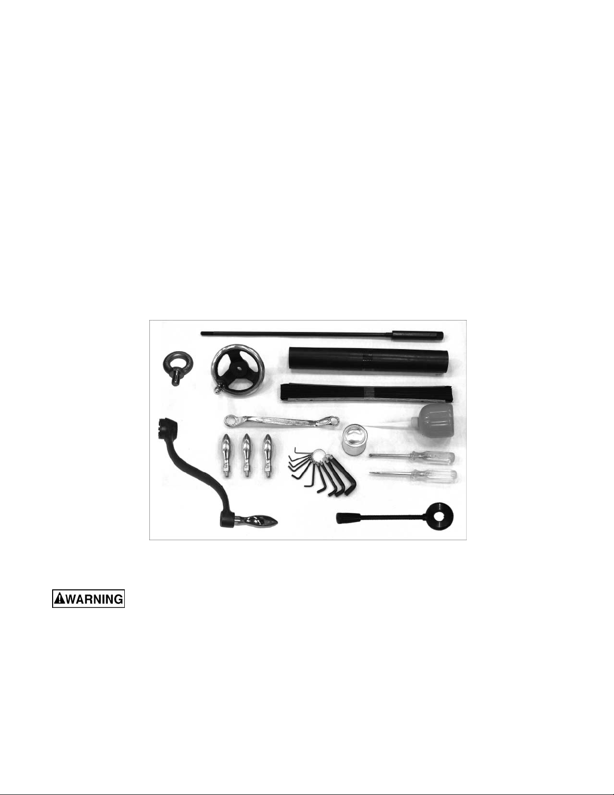
Contents of the Shipping Container
Note: Some parts may be pre-i nstalled on the mill.
1 Turre t Mill ( not shown)
1 Flat Way Cover
1 Pleated Way Cover
1 Draw Bar
3 Table Adjustment Handles
1 Tool Box, containing:
1 Hex Key Set (1.5-10mm) *
1 17/19mm Box Wrench *
1 Cross Point Screw Driver #2 *
1 Flat Blade Screw Driver #2 *
1 Plastic Oil Bottle *
1 Elevating Crank Handle
1 Handwheel
1 Coarse Feed Handle
1 C an Whi te Touch Up Paint
1 Eye Bolt
1 Operator ’s M anual (not shown)
1 Warranty Card (not shown)
* parts with an asterisk are also included in the
tool box service kit, p/n JTM4VS-TB.
Figure 1
Read and understand the entire contents of this manual before attempting set-up or
operation! Failur e t o comply may cause seri ous in jury.
If y o ur mill is suppl ie d with a n optio na l T ab le Po werfeed and/or DRO, be sure to consult the separate instr uction
materials that accompany them.
8
Page 9

Set-up a nd Installation
and-aft leveling. Be certain you get it level in
BOTH directions.
Preparing the Milling Machine for Servi ce
1. Remo ve a ny crating w hic h may be co vering the
machine on the pallet.
2. Remove accessory items from the pallet or
machine table. Compar e these items w ith the list
on the previous page.
3. C heck the tight ness of t he lifti ng ring on t he ram
to be certain it is tight.
4. Check the tightness of the lock handles on the
ram (see Figure 23) to be certain the ram is
locked tight.
5. Remove the nuts a nd/or bolts , which secure the
machine to the pallet.
6. Center an overhead crane or other suitable
overhead lifting device and sling arrangement
over the lifting ring.
Note: This machine weighs over 2400 pounds!
Be certain t he lifting arrangement is new or in
excellent condition and has a safety factor that
will account for age, difficulties in lifting, etc.
When lifting using the ring, the machine will tip
forward. If you wish, you can minimize this tipping
by rigging a support sling over the front of the
machine. Be caref ul when doing t his, to pr event
the sling from damaging any components on the
front of t he machi ne. Be s ure to st eady t he m il l to
prevent it fr om spinning.
7. Lift the machine off the pallet no higher than
necessary to clear the hold- down hardware, then
pull the pallet o ut of the way. Do NOT get hands
or feet underneath the machine when removing
the pallet!
8. Put the machi ne base over the ho ld-down system
where the machine will be spott ed. Anchor bolts
of sufficient size and le ngt h must be fast ened to
the floor accordi ng to the footprint of the mill. See
diagram on page 10.
Note: The accompa nying diagrams show you t he
maximum dimensions of the machines with the
table, ram, etc., fully extended in all possible
directio ns. When spotting the machine be cert ain
to leave room not o nly for t he machine itself, but
also for operator clearance and clearance for
worker s servicing the machine, a nd a ny unusual
sizes of workpieces that might extend off the
machine’s table.
9. When the mac hine is o ver its anchors, le vel t he
machine using shims under t he corner s needi ng
them. The machinist’s level used for leveling
should be placed on the table. The table is the
refer ence surfac e for both side-to- side and fore-
Mill must be supported equally
under a ll fo ur cor ners. Failure to comply may cause
the column to tw ist and put a bi nd in the table ways.
10. When the machine is level, secure the base to
the anchor system.
IMPORTANT: Before attempting to raise the mill
head, refer to Mill Head – Left/Right Adjustment in
the Adjustments section for procedures to safely
raise and set up the mill head.
11. Loose n the four he x head nuts (see A, Figure 22)
about 1/4 turn each (counterclockwise), just
enough to allow rot at ion of the head.
12. While assisting the worm mechanism by putting
upward press ure o n the motor by hand, use t he
wrench supplied with the machine to turn the
worm nut and raise the head to upright position.
13. Tighten the headbolts slightly — not torqued —
just snug.
14. Using mineral spirits or other cleaning solvent,
clean all of the rust proofing from where it may
have been applied. T his is important; mo ving the
table or any other components before removing
the r ust pr oof i ng will o nly p ut rust pro ofing w here
you don’t want it.
Some of the following steps may have already
been perfor m ed on the machine. If so, ignore the
instructions related to those particular steps.
Otherwise, perform them in the order listed,
refer ring to Fi gur e 11 for any clarifi cation.
15. Install the table traverse and cross-feed cranks
on their respective shafts using the nuts on the
shafts to secure the cranks.
16. Remove any r ust proof ing from the drawbar and
its washer, and put the drawbar with washer
installed i nto the spindle ce nter t hro ugh t he top of
the machine.
17. Slide the fine feed handwheel over the
handwheel hub and push it back until its rollpin
engages the hole in the hub and the wheel is
flush with the hub surface.
18. Put t he coar se f eed handle on the feed shaft and
tap it l ig htly unt il its r ol l pin engages a hole in the
hub and it is f l us h against the hub surface.
19. Unwrap and clean the k nee cr ank a nd i nstall it on
its shaft.
20. Install the r ubber way co vers at fr ont and behind
the table.
9
Page 10
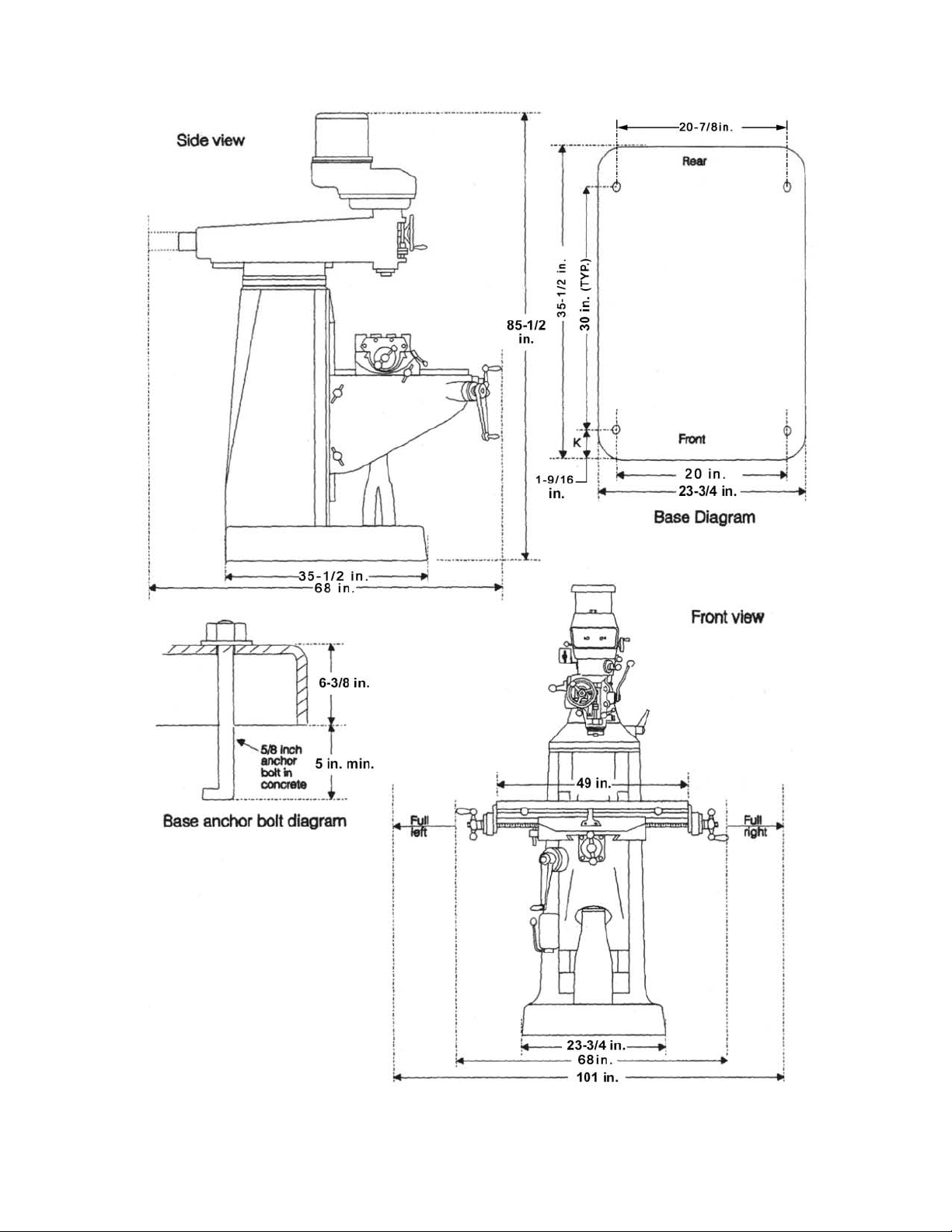
JTM-4VS Dimensions
Figure 2: Install ation Di agr am
10
Page 11
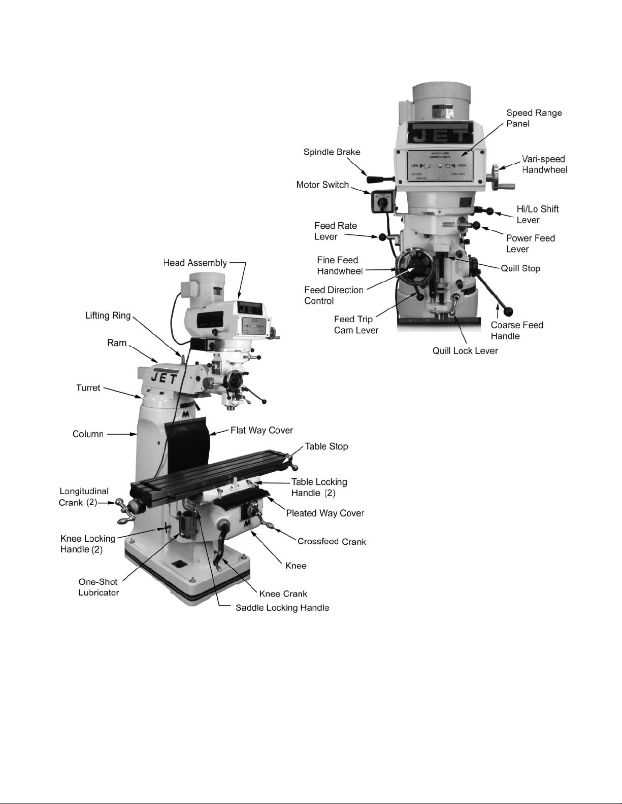
JTM-4V S Over view and Terminology
Figure 3: Ov er view
11
Page 12
Electrical Connections
Operating Instructions
All electrical connections must
be made by a qualified electrician! Failure to
comply may cause serious injur y!
General Electrica l Cautions
This mac hine must be grounded i n accorda nce with
the National Electrical Code and local codes and
ordinances. T his work should be done by a q ualified
electrician. T he machine must be grounded to prot ect
the us er f r om electr ical shock.
Wire Sizes
For circuits which are far aw ay from
the electrical service box, the wire size must be
increased in order to deliver ample voltage to the
motor. To minimize power losses and to prevent
motor overheating and bur nout, the use of wir e sizes
for branch circuits or electrical extension cords
accordi ng to the following table is recommended:
Conductor
Length
0 – 50 Ft. No. 14 No. 14
50 – 100 Ft. No. 14 No. 12
Over 100 Ft. No. 12 No. 8
Confirm that power at the site matches power
requirements of the mill before connecting to the
power source.
The JTM-4VS has been pre-wired for 230 volt
operation. To c hange from 230 V to the ot her voltage
offer ed, remove the junction box co ver o n the motor
and change t he wires acc or di ng to the diagram found
on the inside of the cover.
Before connecting to the power source, make sure
that the switch is in the off position.
The mill must be properly grounded.
Check for pr oper spindle rotat ion in the high-speed
range. The spindle should rotate clockwise when
viewed from the top of the machine. If the spindle
rotates counter-clockwise, disconnect from power
and switch two of t he three power leads.
230/ 460 Vol t Lines 120 V olt Lines
AWG Number
Figure 4
Operati ng Con t rols
The lubricatio n system is a ma nually operated, oneshot system requiring operator intervention. The
operator must lower the one-shot lever to lubricate
the machine ways and ball screws. The one-shot
lubrication system reservoir is located o n t he left side
of the machine.
The positio n of t he milli ng machi ne mill head can be
set up to accommodate the work piece being
machined. T he mill head ca n be set up for a ngles to
the left or rig ht a nd for fore and aft angles. T he mill
head can also be r otated on it s turret. The ram ca n
be moved back and forth to reach work piece
locations at the fore and aft extremes of worktable
travel. Refer to the Adjustments section.
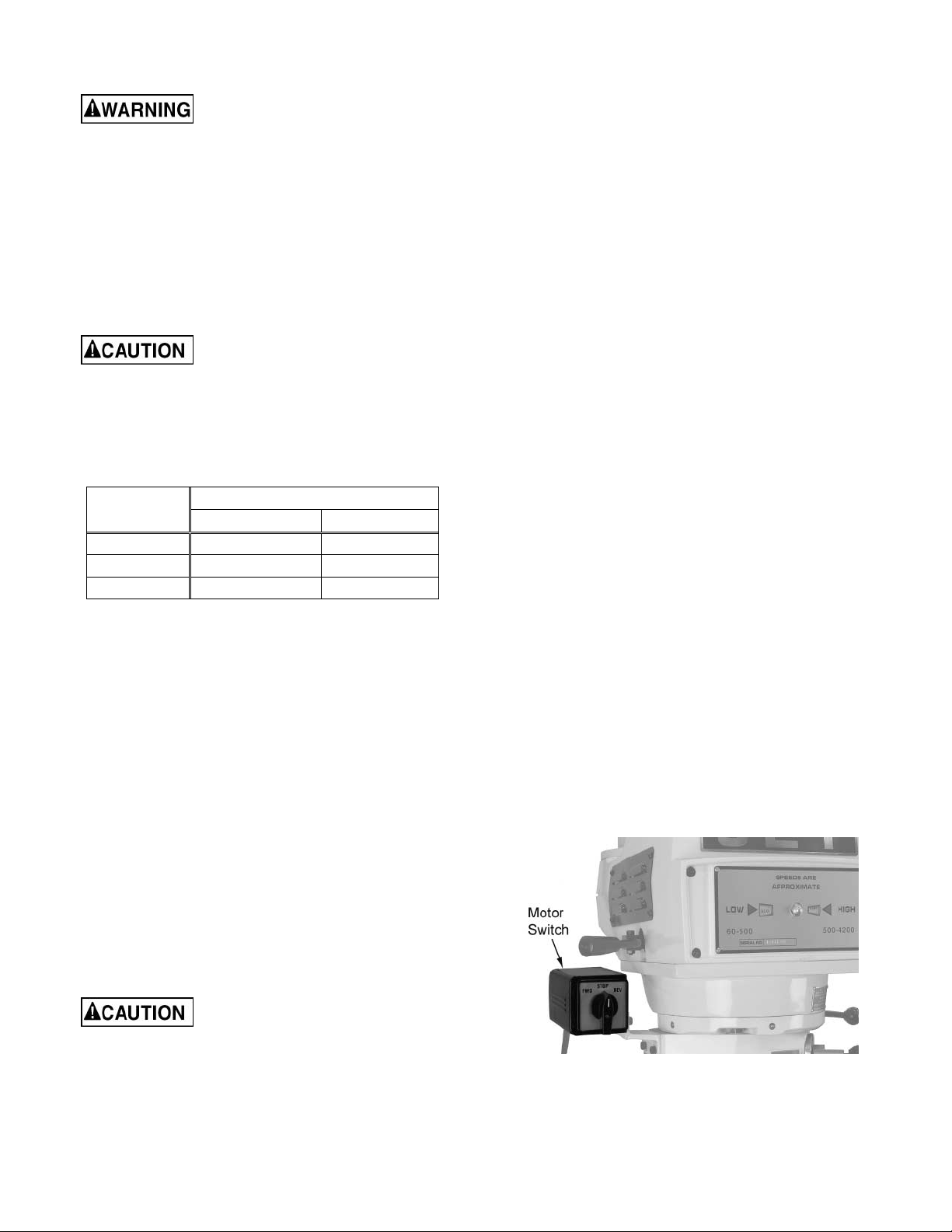
M otor Swi t ch
The Motor Switch is on the upper left-hand side of t he
mill head (Figure 5). The switc h has three posit ions:
FWD (forward), STOP, and REV (reverse).
Setting the switch to FWD will provide clockwise
spindle rotation. Use FWD for normal, right-hand
tooling.
FWD (clockwise) operation occurs only when the
gearbox is in the low speed position. When the
gearbox is in high-speed position, the motor switch
must be i n the REV posit io n to provide r ight- hand or
clockwise rotation. Refer to Figure 6 for a chart of
required switc h positions.
The motor sw itch co ntrols a t hree-p hase motor. The
motor can be sw itched from FWD t o REV a nd back
with the motor running, and will reverse direction
when the switch setting is changed. At higher
speeds, this may put strain on the timing belt but
there will be no damage to the motor or gear
mechanism.
Lubrication
Do not operate the mill before
lubricating the machine fully. Failure to comply
may cause damage to the machine.
Refer to the Maintenance/Lubrication section and
make sure the machine has been fully lubricated
before oper at ing.
Figure 5
12
Page 13

Figure 6
Variable Speed Cont rol
Change speed only while the
spindle is turn ing.
The vari-speed handwheel (A, Figure 7) is used to
control the spindle speed. The speeds for high and
low speed ra nges are disp layed on t he pa nel on t he
front of the mill head (B, Figure 7).
All speed changes must be made while the motor is
running. Att empting speed changes without the motor
running can result in damage to the drive
mechanism.
Figure 7
13
Page 14

Spindle Brake
The spindle brake lever is located on the upper left
side of the m ill head ( Figure 8). P ull lever dow nward
to apply the brake. The spindle brake lever is used
only after the motor switch has been set to OFF. The
spindle will not st op with the motor running.
Figure 8
High-Neutral-Low Shift Lever
The mill head can be dri ven directly ( High Speed) or
through t he back gear (Low Speed) in t he mill head.
The selection is m ade by changing t he posit io n of t he
shift lever.
The shift lever is locat ed at the lower r ight side of the
mill head (Figure 9). The le ver position closest to the
operator is the High set ting. T he lever pos ition aw ay
from the operator is the Low setting. The middle
position is the Neutral setting.
Do not shift the High-Low Gear
Lever while the motor is
running. Rotate the spindle by hand to facilitate
changing lever pos it ion s.
Do not move the Quill Power
Feed Lever unless the motor is
at a complete stop. When changing the lever
position, do it gent l y. If the gear does not engage,
jog the motor and allow it to stop before
attempting to change.
The quill pow er feed le ver is locat ed on t he right s ide
of the mill head (Figure 10). I t is used to engage and
disengage t he quill power f eed mechanism.
The power feed is engaged by pulling out the knob
and rotating the handle to a new locked position.
When engaged, the power f eed mechanism w ill dr i ve
the spindle upward or downward. The power feed
mechanism will not dri ve the spi ndle w hen t he handle
is in the disengage position.
Figure 10
Feed Rat e Lever
The Feed Rate Lever (Figure 11) is used to set the
per-revolution rate of the power feed mechanism.
Three feed rates are available: 0.0015-inch, 0.003inch, a nd 0.006-i nch per r evo l utio n. T he positions are
shown on an indicator plate under t he feed rat e lever.
The rate is selected by pulling out the knob on the
feed rat e lever and moving the handle to the detent of
the desired feed rat e.
Note: The knob is spring loaded – pull out t o r ot at e to
new po s ition.
Figure 9
Quill Power Feed Lever
Do not use power feed at speeds
above 3000 R.P.M.
It is reco mmende d to disengage
the power feed worm gear
whenever the power feed is not required. This
avoids unnecessary we ar on t he worm gear.
Unlike other controls o n the machi ne, the lever s hifts
into engageme nt more easily with t he motor running,
and the quill feed lever engaged.
Figure 11
14
Page 15

Feed Trip Cam L ever
The Feed Trip Cam Lever (A, Figure 12) is located on
the left side of the head behind t he Manual Fine Feed
Handwheel (B, Figure 12). It engages t he o verload
clutch on the pinio n shaft when positioned to the left .
The Feed Trip Cam L ever stays e ngaged until Quill
Stop (C, Figure 15) comes in contact with Micrometer
Adjusting Nut (A, Figure 15) forcing it to drop out
automatically, or until it is released manually by
engaging the lever to t he right.
Figure 12
Coarse F eed Handl e
The Coarse Feed Handl e (A, Figure 14) is located on
the right side of head. The Coarse Feed Handle is
used for non-precision drilling operations and for
moving the quill to a specific depth. A return spring
will r et rac t t he s pi ndle a uto mat ica lly o nce the hand le
is released.
Quill Lock Lever
The Quill Lock Lever (B, Figure 14) is locat ed o n the
right side of the head. Rotate the handle clockw ise to
lock the quill in a desir ed positio n. Rotate t he handle
counter-clockwise t o r elease.
Feed Direction Cont rol
The Feed Dir ecti on Co ntrol (B, Fig ure 13) det er mines
whether the power feed will move up, down, or not
move at all. The posit ion of the knob depe nds upon
the direction of spindle rotation (see the Motor Switch
section). T he position of the control may b e changed
with the system stopped or running. If the control
does not engage easily, move the fine feed
handwheel (A, Figure 13) back and forth to aid
engagement.
If the spindle is rotating clockwise, in is downfeed; out
is upfeed. If the spindle rotat ion is counterclockw ise,
out is downfeed; in is upfeed. Neutral position is
between the in and out position.
It is recommended t hat the Feed
Direction Knob be left in the
neutral posit ion whe n not in use.
Figure 14
M i crometer Adj ustin g Nu t
The Micrometer Adjusting Nut (A, Figure 15) is
located on the front of the head. Use for setting
specific spindle depth. Secure with the lock nut (B,
Figure 15).
Fine Feed Handwheel
When the controls are set for the Fine feed using
Handwheel position (see Figure 6), the Fine Feed
Handwheel (A, Figure 13) can be used for manual
fine feed control in either upward or downward
directio n of the quill.
Remove the Manual Fine Feed
Handwheel when not in use.
Failure to comply may cause ser ious injury.
Figure 13
15
Page 16

Depth Scale and Stop
Referring to Figure 15:
The Depth Scale and Stop are used in drilling
operations t o set the dept h of t he dril led hole. T he
depth scale is located o n the front of the mill he ad.
The scale consists of a Micrometer Adjusting Nu t (A),
Lock Nut (B), Quill Stop (C), Quill Stop Screw (D),
and Scale (E).
The Micrometer Adjusting Nut is set to the desired
dimension and locked in place using the Lock Nut.
The quill stop provides a positive stop f or quill travel.
The graduations on the micrometer nut are in
0.001-inch increments. Adjustment of q uill travel is
made by rotating the micrometer nut.
9. Select f eed r at e with the Variable Speed Control
Handwheel (E).
10. Set the Feed Rate Lever (B) to the feed rate
required for the tooling and material requir ed.
11. Place the Quill Feed Engagement Lever (F) in
the Engaged position.
12. Select feed direction by setting t he Feed
Direction Knob ( C) posit ion per the table:
Spindle Dir. Feed Dir. Knob Pos.
Down In
CW
Up Out
Down Out
CCW
Up In
Figure 16
13. Engage the Feed Trip Cam Lever (D) by pulling
away from head assembly.
Note: Due to variables in tool diameter, coatings,
coolant, and materials, no specific spindle speed or
feed rate recommendations are provided. Use
general shop manuals that have data applicable to
the milling and drilling operations being performed.
Or, contact the supplier of the tooling, coolant, and
material for specific recommendations.
IMPORTANT: The pow er feed ca n be used for drills
up to 3/8” in diameter (mild steel). Use manual feed
for drills la r g e r than 3/8” .
Figure 15
Power Feed Op erat ion
The Feed Trip Adjustment sets t he point at which the
quil l will res e t duri ng Po wer Feed.
Referring to Figure 17:
Be sure that the Manual Fine
Feed Handwheel is removed.
Failure to comply may cause ser ious injury.
1. Loos en the Lock nut (I ) .
2. With the Quill Feed Handle (J ), advance the quill
to the point where the feed should stop.
3. Engage the Feed Trip Cam Lever ( D) by pulling
away from head assembly.
4. Adjust Mi cr om eter Adjusting Nut (H) against
Quill Stop (G).
5. Continue turning the Micrometer Adjusting Nut
(H) until the Feed Tr ip Cam Lever (D) tri p s .
6. Tighten the Locknut (I).
7. Ensure Quill Lock (K) is disengaged by rotating
counter-clockwise.
8. St ar t the spindle (A):
T he overload clutch is f act ory set
to hold up to 200 lbs. downfeed pressure on t he
quill (accommodates drills up to 3/8”). Do not
attempt t o adjust clutch pr essure.
Figure 17
16
Page 17

Draw Bar Operatio n - Chan ging Tooling
1. Using the wrench provided with the machine,
loosen the draw bar two or three turns (turn
counterclockwise) using the draw bar hex
(Figure 18).
Figure 18
2. Tap the top of the draw bar with a soft-faced
hammer to loosen the collet fr om the taper.
Adjustments
Mill Head – Left/Right Adjustment
Make sure the machine base is
secured to t he floor before repositioning t he mill
head. The center of gra vity can shift enough to
cause the machine to tip over, resulting in
serious in jury to the o perator and da mage t o the
machine.
1. Loosen four large hex nuts that secure the mill
head to the ram adapter (ref er to Figure 20).
1/4 turn should be sufficient to allow the head to
move.
NOTE: For angles greater than 10 degrees, use your
free hand to support the mill head, taking some
weight off t he brass w or m gears. Doi ng so will great ly
lengthen the life of t he wor m gears.
3. Remove the tool from the collet.
4. Insert the tool you are going to use into the collet.
5. Tighten the draw bar firmly using the wrench
provided with the machine. Turn the draw bar.
The tool is now ready for use.
Clamp i ng Work Piece to the Table
1. The worktable has 5/8-inch T-slots for clamping
the work piece to the table.
2. Set motor switch to STOP position.
3. Place the work piece on the table.
4. Clamp the work piece using the T-slot clamps,
studs, and step blocks as required (Figure 19).
Figure 20
2. Turn the worm nut (B, Figure 20) to tilt the head
left or r ight as required. Use the scale on the ram
adapter t o set the desired angle.
Note: The scales on the ram adapter and for
head rotation are guides only. Close tolerance
work will require the use of a dial indicator to
make sure t he head is 90° to the t able in the X
and Y a xis. P lease note the t able is fitted t o be
slightly higher in front, usually about 0. 0005” .
Figure 19
Be sure to apply torque in two
steps using a crossing pattern. Failure to do so
could distort t he f ace of the r am adapter.
3. Tighten the four hex nuts. Tighten in two steps
using a calibrated torque wr ench. Use a crossi ng
pattern to tighten the nuts. Tighten i nitially to 25
foot-pounds.
17
Page 18

4. Bef ore applying f inal torque, c heck to make s ure
the mill head is perpendicular to the wor kt able.
5. Set up a dial indicator in a collet and secure
using the draw bar (ref er to Figure 22).
2. Returning to upright position:
a. When retur ning the mill head to its full upright
position, be sure to support t he head by upward
pressure on the spindle as you turn the worm nut.
6. Put the spindle drive in neutral.
7. Set the dial indicator plunger on the worktable.
Zero the indicator.
8. Rotate the spindle 180 degrees (when rotating,
raise the dial indicator plunger by hand to prevent
it from dropping into the table T-slots) .
9. Read the dial indicat or . The indicator should read
zero. If not, loosen the four hex nuts and
repositio n the mill head.
10. Recheck p er pendic ular ity using t he dia l i ndicat or .
Repeat the procedure above until the dial
indicator reads zero in both positions.
Be sure to apply torque in two
steps using a crossing pattern. Failure to do so
could distort t he f ace of the r am adapter.
11. Tighten the four hex nuts. Tighten in two steps
using a calibrated torque wr ench. Use a crossi ng
pattern to tighten the nuts. Tighten i nitially to 25
foot-pounds, then tighten to a final torque of 50
foot-pounds.
M il l Head – Fore/Aft Adjust ment
1. Setting the angle:
a. Loosen the t hree ram adapter clamp bolts on
the ram (A, Figure 21). There is no need to
loosen the bolts more than 1/2 turn to allow
tilting.
b. Check to make sure t he mill head is p erpendicular to the worktable.
c. Set up a dial indicator in a collet and secure
using the draw bar (ref er to Figure 22).
Figure 22
d. Put the spindle drive in neutral.
e. Set t he dial i ndicat or pl unger on the workt able.
Zero the indicator.
Figure 21
b. Support the mill head with your free hand.
Press upward on the spindle when changing the
angle.
c. Turn t he ram adapter worm nut (B, Fig ure 21)
to tilt the head forward and backward. Use the
scale on the ram adapter to locate the desired
angle.
f. Rot ate the spindle 180 degrees ( when rotating,
raise the dial indicator plunger by hand to prevent
it from dropping into the table T-slots) .
g. Read the dial indicator. The indicator should
read zero. If not, loosen the four hex nuts and
repositio n the mill head.
h. Recheck perpendicularity using the dial
indicator. Repeat the proced ure abo ve until t he
dial indicator reads zero in both positions.
i. When the i ndicator r eads zero, tig hten the ram
adapter clamp bolts.
18
Page 19

Positioning the Ram
Positioning t he Ram Fore and Aft
1. Loose n the tw o bolts (A, Fig ure 23) t hat lock t he
ram to its ways.
Figure 23
2. Turn the lever (B, Figure 23) to move the ram on
its ways.
Figure 24
Adjustment of Knee G ib
The knee gib adjustment screw (A, Figure 24) is
located under the chip w iper at the rear of the knee
where it co ntacts the colum n. Remove the way cover
and the wiper to expose t he gib adjustment screw.
Tighten the screw until a slight drag is felt when
turning the knee crank.
3. When the desired position is reached, lock the
bolts (A, Figure 23) securely.
Positioning t he Ram on its T ur re t
Make sure the machine base is
secured to t he floor bef or e r eposition ing the ra m.
The center of gravity can shift enough to cause
the machine to tip over, resulting in serious injury
to the operat or and damage to t he machine.
1. Loosen four turret lock bolts (C, Figure 23) that
clamp the ram to the top of the base. 1/2 turn
should be sufficient to allow the turret to move.
Note: Use gentle hand pressure to avoid rapid
movement.
2. Turn the ram until the spindle is in the desired
position. Use the scale on the turret for degree
measurement.
3. Tighten the four turret lock bolts (C. Figure 23).
Gib Adjustment
The table, saddle and knee are equipped with
adjustable gibs. The gibs may require adjustment if
unusual vibration is noted when the locking
mechanisms are off, or if you experience unusual
vibratio n when spindle speed, toot h pitch or dept h of
cut do not account for the vibration.
Adjustment of Saddl e G ib
The saddle gib adjustme nt screw is on the left front of
the saddle (B, Figure 24). Tighten the screw until a
slight drag is felt w hen turning the cross-f eed cr ank.
Adjustment of Table Gib
The table gib adj ustm ent screw ( C, Figure 24) is o n
the left-hand side, beneath the table. Tighten the
screw until a slight drag is felt when turning the
longitudi nal table cra nks.
NOTE: When adjusting gibs, always start with the
knee first; adjust the saddle second, and adjust the
table last.
19
Page 20

Power Feed T rip Lever M echanism
Refer to Figure 25.
The power f eed trip lever mec hanism will need to be
adjusted if worn or whenever any trip lever
mechanism compo nents are r eplaced.
1. Loosen the feed trip adjusting screw lock nut.
2. Loose n the adjusting screw until it is loose in the
lever and no longer contacts the bottom of the
feed tr ip plunger.
3. Using the coar se feed ha ndle, mo ve t he q uill to
the bottom of its travel so the quill stop contacts
the micrometer nut. Hold the quill on the stop.
4. Pull the feed handle out to engage the power
feed system.
5. Tur n the feed t rip adjusti ng screw unti l the power
feed disengages.
power f eed. I f not, readjust t he mechanism until
positive dise ngage me nt occ urs when the q uill is
at the top of its stroke.
10. Check for cor r ect operat ion using the coarse f eed
handle. If operating correctly, start the drive
motor and engage the power feed mechanism.
Verify that the power feed lever correctly
engages and disengages when driven by the
drive motor.
Tab le Lead Screw Backlash Adjust ment
Refer to Figure 26.
The milling machi ne table is moved by a lead screw
and nut for each mac hine a xis. For pr oper operat ion,
there m ust be clearance between the lead screw and
the nut, which results in backlash. A second lead
screw nut is provided to eliminate most of the
backlash. The following procedures provide
instructions for obtaining acceptable backlash.
6. Tighten the feed tr ip adjusting scr ew .
7. Release the quill stop so you can engage the
power f eed mechanis m using the power f eed trip
lever.
8. Using the coarse feed handle, pull the quill s top
back into firm contact with the micrometer nut.
Cross Feed Backlash Adjust ment
1. Use the cross feed crank to move the table to t he
extreme rear of its travel.
2. Remove the pleated way cover.
3. O pen the two c hip guards e nough to e xpose the
cross-f eed adjustment nut (the nut t hat is towar d
the rear of t he nut bracket is not adjustable – only
the front nut is adjustable).
4. Loosen the two nut locking screw s.
5. Turn the nut slightly to tighten it against the
opposing nut.
6. Tighten the two nut locki ng screw s.
7. Using the cross-feed crank, move the tab le t o t he
midd le po s ition.
8. Set up a dial indicator to check cross-feed
backlash. Gently mo ve t he cross f eed c r ank back
and forth while watching the dial indicator.
Backlash should be between 0.003 inch and
0.005 inch.
9. If necessary, repeat the steps above to set
backlash.
Figure 25
Note: The power feed should disengage when the
quill stop pushes on the micrometer nut. If it does not
disengage, repeat t he adjustment steps above.
9. Engage t he power f eed and move the q uill stop
to the top of its travel. Make sure that the
reverse trip mechanism also disengages the
10. Install the pleated w ay cover.
Longitudina l Back lash Adjustment
Refer to Figure 26.
1. Only one of t he longitudi nal lead screw nuts can
be adjusted. The other nut is fixed. The left hand
nut is typically adjustable. This can be
determined by looking at the nut from the
underside of t he table.
2. Loosen the two nut locking screw s.
3. Turn the nut slightly to tighten it against the
opposing nut.
20
Page 21

4. Tighten the two nut locki ng screw s.
5. Using the longitudina l table cr ank, move the table
to the middle position.
6. Set up a dial indicator to check longitudinal
backlash. Gently mo ve t he cra nk back a nd fort h
while watching the dial indicator. The backlash
should be between 0.003 inc h and 0.005 inch.
If necessary, r epeat the steps above to set backlash.
Figure 26
21
Page 22

Maintenance
Before any intervention on the machine, disconnect it from the electrical supply by
pulling out t he plug or switchi ng of f t he main switch! Failure to com ply may cause seri ous in jury.
Lubrication
The milling machine is eq uipped wit h a “one-s hot” lubricat io n system. T he system l ubricates the lead screw s
and ways. An oil c up and grease nipple on the mi ll head provide lubrication for t he spindle beari ngs a nd back
gear mechanism. Refer t o Figures 28 and 29 for lubrication require me nts and access points.
Key Description Recommended Lubricant Action
A Spindle bearing oil cup Mobil DTE Oil Lig ht, or equivalent Service daily.
Check oil daily – add if required.
B One-shot lube system Mobil Vactra Oil #2, or equivalent
Knee leadscrew grease
C
nipple
Mob ilith AW2, or e qui valent Serv ic e o nce each week .
Pull lube handle every hour
during operations.
D Back gear gr ease nipple Mobilith AW1, o r equiva lent
Figure 27: Lubri cation Points
Periodic Maintenance Requirements
During operation, periodically vacuum and brush
chips and debris from machine.
Periodically operate knee and table lead screws
t hro ug h f ull r a ng e of mo ve me nt to eve nl y d is tr ib ut e
lubricant (particularly when applied using the “oneshot” system).
Periodically apply light machine oil to w or k t able and
other exposed metal surfaces to prevent rust or
corrosion.
Figure 28
Periodically remove vent panels to check pulleys
and belts for unusual wear or grooving. NOTE:
Operators should vary speed occasional l y to prevent
form ation of groov es on the pulley surfaces .
Service weekly when operating
in back gear mode.
Figure 29
22
Page 23

Repl acement o f Drive Motor
Refer t o Figure 30 and Head Assembly in the Parts
section.
Figure 30
1. Operat e spindle at its highest speed.
Disconnect electrical power to
the machine before per f or ming any ma intenance.
2. Disconnect electrical power. Remove junction
box cover and disconnect wiring. Tag wires to
identify leads for r einstallation.
3. Remove vent covers on both sides of head to
provide access to the vari-speed belt a nd pulleys.
4. Remove the lower cover plate under the motor
pulley (at the rear of t he cover) by removing three
cap screws.
5. Remove the four screws that attach the motor.
6. Connect a lifting sling to support and lift t he motor
during removal. Ease the motor up and forward
on the ho using.
7. Tilt the motor sl ightly toward t he rear t o slacken
the vari-speed belt. Remove the vari-speed belt
from the motor pulley.
10. Slowly release pressure on hydraulic ram until
the spring (ref. 8) is fully extended.
11. Remove the lengthening shaft (ref. 106), spring
stop w asher (r ef . 9), spr ing (ref . 8) and outermost
pulley (ref. 5) from the motor shaft.
12. Loosen set screw (ref. 3) on innermost pulley
(ref . 2). Remove t he pulley (ref. 2) and dri ve key
(ref. 7) from the motor shaft.
13. Install drive key (ref. 7) and pulley (ref. 2) on
shaft of replacement motor. Tighten set screw
(ref. 3) on pulley.
14. Support the drive motor in a hydraulic press.
Place the outerm ost pulley (ref . 5) on the motor
shaft.
15. Install the spri ng (ref. 8), spr ing stop washer (ref.
9), and le ngtheni ng shaft (ref . 106) o n t he motor
shaft.
16. Move the hydraulic ram into contact with the
spring stop washer (ref. 9) . Compress the spring
(ref . 8) and insta ll the lengtheni ng s haf t ( r ef . 106)
on the motor shaft. Install and tighten the
attaching scr ew (ref. 107) in t he end of the motor
shaft.
17. Using an overhead hoist, lift the replacement
moto r int o po s ition.
18. Tilt the motor slightly towar d the rear and i nstall
the vari-speed belt on the motor pulleys.
19. Install the four motor at t ac hing screws.
20. Install lower cover plate.
21. Connect electr ical wir i ng to motor junction box.
22. Start the drive motor. Operate the spindle
throughout its speed r ange to check operatio n.
23. Install vent cover s on mill head.
8. Remove the belt; lift the motor clear of the
housing.
Do not attempt to remove the
screw from the end of the motor shaft without
use of a hydraulic press. Failure to comply may
cause serious injury .
The screw ret ains the underlying spring stop w asher,
which is under spring tension. Serious injury can
result if the spring tension is not gradually released
using the hydraulic press. Pr oceed as f ollow s.
9. Support the drive motor in a hydraulic press.
Move the hydraulic ram into contact with the
spring stop washer (ref. 9). Remove the screw
(ref . 107) from the end of the motor shaft.
Figure 31
23
Page 24

Repl acement o f V ari-Speed Belt
Refer t o Fig ures 31 and 32, and Head Assembly in
the Parts sectio n.
Disconnect electrical power to
the machine before per f or ming any ma intenance.
1. Remove drive motor (refer to the Replacement of
Dri v e Motor sect ion).
2. Remove Quill Top Cover by removing three cap
screws (Figu re 31).
3. Remove six cap screws and remove the upper
housing (Figure 32).
4. Remove the vari-speed belt ( r ef . 4).
5. Install the new vari-speed belt (ref. 4) on the
driven hub (ref. 44) .
6. Install drive motor (refer to the Replacement of
Dri v e Motor section).
Figure 33
6. Pull the pi vot f inger stud (ref . 58) out of the lower
housing cover (ref. 50) and the brake pivot
fingers (ref. 59).
7. Before removing, note the orientation of the
brake pivot f ingers ( r ef. 59) for corr ec t posit ioning
for re-assembly. Remove t he pivot fingers.
If replac ing the brake components onl y, ski p Steps 8
and 9 and go to Step 10.
To replace the tim i ng belt:
8. Remove lower housing cover a nd pulley.
Figure 32
Repl acement o f Brake S hoes, S prings and/or Timing Belt
Disconnect electrical power to
the machine before per f or ming any ma intenance.
1. Remove drive motor (refer to the Replacement of
Dri v e Motor section).
2. Remove vari-speed belt and upper housing (r efer
to the Replacement of Vari-Speed Belt section).
3. Remove screws from lower housing cover
(ref. 50).
4. Loosen the setscrew (ref. 3) securing the brake
pivot finger stud (ref. 58) in the lower housing
cover (ref. 50).
5. Move the pivot finger stud (ref. 58) inward
enough to remove the snap ring (ref. 60).
9. Replace belt (r ef 63).
To replace the brak e com ponents:
10. Using a soft- f ac ed mallet, tap upward to separ at e
the lower housing cover (ref. 50) and the brake
assembly (ref. 47) from the bearing (ref. 43).
11. Remove the brake shoes (ref. 47) and springs
(ref . 49). I nstall the replacem ent brake shoes and
springs.
For all:
12. Position the brake pivot fi ngers (ref. 59) as noted
during removal. Install the pivot finger stud (ref.
58) thro ugh t he low er housing cover (ref. 50) and
into the brake pivot fingers (ref. 59). Install the
snap ring (ref. 60) on the pivot finger stud (ref.
58).
13. Tighte n t he sets crew (ref . 3) to secure the pi vot
finger stud (ref. 58).
14. Install t he brake assemb ly (ref. 47) on the lower
housing cover (ref. 50).
15. Secure the lower housing cover (ref. 50) with four
screws.
16. Install timi ng belt and upper housi ng.
17. Install vari-speed belt (refer to the Replacement
of Vari-Speed Belt section).
18. Install drive motor (refer to the Replacement of
Dri v e Motor section).
24
Page 25

Repl acement o f Qu ill Feed Clock Sp rin g
Refer to the Spindle Assem bly in the Parts sectio n.
Disconnect electrical power to
the machine before per f or ming any ma intenance.
1. Remove the coarse feed handle.
2. Remove the screw, hub, and key from the coarse
feed shaft (r ef. 172, 175, and 171).
3. Remove six screw s (Ref. 1) and allow t he clock
spring (ref. 178) to slowly unwind.
4. Remove feed handle hub sleeve (ref. 176).
5. Lift t he end of the s pring (ref. 178) from the pin
(ref . 168) on the pinion shaft (ref. 166).
6. Remove the spring (ref. 178) from the spring
cover (ref. 177).
7. Install the replacement spring (ref. 178) in the
spring cover (ref 177) .
8. Install end of spring (ref. 178) over the pin
(ref . 168) on pinion shaft (r ef. 166).
9. Install pin (ref. 168) in feed handle hub sleeve
(ref . 176) on other end of spring (ref. 178).
10. Turn the spring cover (ref. 177) t o wind the spring
(ref. 178). Turn the spring cover (ref. 177) until
the desired t ension is ac hieved. Hold t he spring
cover (ref. 177) in position and secure with six
screws (ref . 1).
11. Install t he key, hub, a nd screw ( r ef. 171, 175, and
172) onto the feed shaft (ref. 166) .
Replacement Parts
Replacement p arts ar e listed o n t he follow ing pages. To or der part s or reac h o ur ser vice departme nt, call 1-800274-6848, M onday through Fr iday (see o ur website for business hours, www.waltermeier.com). Having t he Model
Number and Serial Number of your machine available when you call will allow us to serve you quickly and
accurately.
25
Page 26

Head Ass embly
26
Page 27

Parts L ist for Head Assembl y
Index No. Part No. Description Size Qty
................ JTM4 V S-HA ............Head Assembly w/ M ot or................................................................................. 1
1 .............. VS-001....................Upper Housing ............................................................................................... 1
2 .............. VS-002....................Motor Pulley ................................................................................................... 1
................ VS -044A .................Motor Pulley Bushing (not shown) .................................................................... 1
3 .............. TS-1503011 ............Set Screw ........................................................M6 x 6.................................... 4
4 .............. VS-004....................Belt ..................................................................900VC3830 ............................ 1
5 .............. VS-005....................Motor Pulley Disk............................................................................................ 1
6 .............. VS-006....................Motor Pulley Shaft .......................................................................................... 1
7 .............. KEY7725.................Key ..................................................................7 x 7 x 25 mm......................... 1
8 .............. VS-008....................Motor Pulley Spring ........................................................................................ 1
9 .............. VS-009....................Spring Stop Washer ........................................................................................ 1
11 ............ VS-011A .................Motor Pulley Cover ......................................................................................... 1
12 ............ TS-1502051 ............Hex Socket Cap Screw .....................................M5 x 20 .................................. 8
13 ............ VS-013....................Cover ............................................................................................................. 1
14 ............ TS-1503041 ............Hex Socket Cap Screw .....................................M6 x 16 ................................ 10
15 ............ BB-6007ZZ ..............Ball Bearing.................................................................................................... 1
16 ............ VS-016....................Dial Cover ...................................................................................................... 1
17 ............ TS-1503071 ............Hex Socket Cap Screw .....................................M6 x 30 .................................. 4
18 ............ TS-1503041 ............Hex Socket Cap Screw .....................................M6 x 16 .................................. 2
19 ............ VS-019....................Bushin g.......................................................................................................... 1
20 ............ VS-020....................Bushin g.......................................................................................................... 1
21 ............ VS-021....................Worm ............................................................................................................. 1
22 ............ VS -0 2 2....................Wo rm Gear .................................................................................................... 1
23 ............ VS-023....................Spring Pin ........................................................5 x 10 mm .............................. 2
24 ............ VS-024....................Bushin g.......................................................................................................... 2
25 ............ VS-025....................Dial Control Shaft ........................................................................................... 1
26 ............ VS-026....................Spring Pin ........................................................3 x 12 mm .............................. 1
27 ............ VS -0 2 7....................D i a l Wheel ..................................................................................................... 1
28 ............ VS-028....................Wh eel Handle................................................................................................. 1
29 ............ VS-029....................Shaft .............................................................................................................. 1
30 ............ VS-030....................Spring Pin ........................................................4 x 16 mm .............................. 2
31 ............ VS-031....................Spring Pin ........................................................3 x 25 mm .............................. 1
32 ............ VS-032....................Speed Change Chai n ...................................................................................... 1
33 ............ VS-033....................Adjustment Stud ............................................................................................. 1
34 ............ VS-034....................Sleeve Nut ..................................................................................................... 1
35 ............ VS-035....................Adjustment Stud ............................................................................................. 1
36 ............ VS-036....................Tilter .............................................................................................................. 1
37 ............ VS-037....................Bushin g.......................................................................................................... 2
38 ............ KEY6645.................Key ..................................................................6 x 6 x 45 mm......................... 1
39 ............ VS -0 3 9....................R e gula tin g Scre w .................................................................... ....................... 1
40 ............ VS-040....................Spring Pin ........................................................3/32” x 3/4"............................. 1
41 ............ VS-041....................Washer .......................................................................................................... 1
42 ............ VS-042....................Support .......................................................................................................... 1
43 ............ BB-6010VV .............Ball Bearing.................................................................................................... 2
44 ............ VS-044....................Driven Pulley Assembly (s/n:xxx1944 & lower ) .................................................. 1
................ VS-044N .................Driven Pulley Assembly (s/n:xxx1945 & higher) ................................................ 1
45 ............ VS-045....................Steady Pulley (s/n: xx x1944 & lower) ................................................................ 1
................ VS -0 4 5N .................Steady Pulley (s/ n: xx x1945 & higher) ............................................................... 1
46 ............ VS-046....................Bearing Cover ............................................................................................... 1
47 ............ VS-047....................Brake Linin g ................................................................................................... 1
48 ............ VS -0 4 8....................Lo c k Scre w .................................................................................................... 1
49 ............ VS-049....................Brake Spring .................................................................................................. 2
50 ............ VS-050....................Lower Housing Cover...................................................................................... 1
51 ............ TS-1504031 ............Hex Socket Cap Screw .....................................M8 x 20 .................................. 4
52 ............ VS-052....................Brake Shaft Sleeve ......................................................................................... 1
53 ............ VS-053....................Brake Lock Shaft ............................................................................................ 1
54 ............ VS-054....................Brake Lock Block ............................................................................................ 1
27
Page 28

55 ............ TS-1503061 ............Hex Socket Cap Screw .....................................M6 x 25 .................................. 1
56 ............ VS-056....................Brake Lock Ha ndle ......................................................................................... 1
57 ............ VS-057....................Plastic Ball ..................................................................................................... 2
58 ............ VS-058....................Brake Finger Pivot Stud .................................................................................. 1
59 ............ VS-059....................Brake Stud ..................................................................................................... 2
60 ............ VS-060....................Snap Ring ........................................................S-8 ........................................ 2
61 ............ TS-0561072 ............Nu t ..................................................................5/8” -1 8 UNF ........................... 1
62 ............ VS-062....................Timing Belt Pulley ........................................................................................... 1
63 ............ VB-225L100 ............Timing Belt .......................................................225L100................................. 1
64 ............ VS-064....................Bearing Retainer............................................................................................. 1
65 ............ BB-6203ZZ ..............Ball Bearing.................................................................................................... 2
66 ............ VS-066....................Bull Gear ........................................................................................................ 1
67 ............ VS-067....................Counter Shaft ................................................................................................. 1
68 ............ VS-068....................Key ..................................................................5 x 5 x 15 mm......................... 1
69 ............ VS-069....................Key ..................................................................5 x 5 x 18 mm......................... 1
70 ............ VS -0 7 0....................S p indle Pu ll ey H ub ......................................................................................... 1
71 ............ VS-071....................Key ..................................................................8 x 7 x 24 mm......................... 1
72 ............ VS-072....................Key ..................................................................8 x 7 x 12 mm......................... 1
73 ............ VS-073....................Spindle Gear Hub ........................................................................................... 1
74 ............ VS-074....................Spindle Gear Assembly ................................................................................... 1
75 ............ VS-075....................Rack Cup ....................................................................................................... 1
76 ............ VS-076....................Washer .......................................................................................................... 1
77 ............ BB-6908ZZ ..............Ball Bearing.................................................................................................... 2
78 ............ VS-078....................Bearing Washer .............................................................................................. 1
79 ............ VS-079....................Bearing Washer .............................................................................................. 1
80 ............ VS-080....................Snap Ring ...................................................................................................... 1
81 ............ VS -0 8 1....................N ut ................................................................................................................ 1
82 ............ VS -0 8 2....................Lo we r Hous ing ............................................................................................... 1
83 ............ VS-083....................Fixed Clutch Bracket ....................................................................................... 1
84 ............ VS-084....................Spring ............................................................................................................ 1
85 ............ VS-085....................Stud ............................................................................................................... 3
86 ............ TS-1506021 ............Hex Socket Cap Screw .....................................M12 x 25 ................................ 3
87 ............ VS-087....................Gear Shift Pinion ............................................................................................ 1
88 ............ VS-088....................Pin ................................................................................................................. 1
89 ............ VS-089....................Detent Plate ................................................................................................... 1
90 ............ VS -0 9 0....................D e te nt Wash e r ....................................................................... ........................ 1
91 ............ VS-091....................Spring ............................................................................................................ 1
92 ............ VS-092....................Pinion Block ................................................................................................... 1
93 ............ TS-1503011 ............Hex Socket Cap Screw .....................................M5 x 14 .................................. 2
94 ............ VS -0 9 4....................P inion Cr ank .................................................................................................. 1
95 ............ VS -0 9 5....................C a p Nu t ......................................................................................................... 1
96 ............ TS-0561031 ............Hex Nut............................................................3/8” ........................................ 1
97 ............ VS-097....................Snap Ring ...................................................................................................... 1
98 ............ VS-098....................Wave Washer................................................................................................. 1
99 ............ VS-099....................Plastic Ball ..................................................................................................... 1
100 .......... VS-100....................S nap Ring ...................................................................................................... 1
101 .......... VS-101B .................Cover ............................................................................................................. 2
102 .......... VS-102....................S p ring Sh a ft ................................................................................................... 3
103 .......... VS-103....................Wa s her .......................................................................................................... 1
104 .......... VS-104....................C opper Washer .............................................................................................. 2
105 .......... VS-105....................Screw ..............................................................1/4" x 3/8”............................... 8
106 .......... VS-107....................S h a ft .............................................................................................................. 1
107 .......... TS-1504061 ............Hex Socket Cap Screw .....................................M8 x 30 .................................. 1
109 .......... VS-109....................L o ck Was her .................................................................................................. 1
110 .......... TS-1540041 ............Hex Nut............................................................M6 ......................................... 1
111 .......... TS-0209051 ............Hex Socket Cap Screw .....................................3/8” x 1” ................................. 4
112 .......... VS-000....................Mo to r ...............................................................3H P 3PH ................................ 1
................ JTM4 V S-112 ...........Motor ...............................................................2H P 1PH ................................ 1
113 .......... VS-113....................Oval Head Screw..............................................1/8” x 1/4"............................... 4
114 .......... JT M1 -001VS ...........Draw Bar ........................................................................................................ 1
115 .......... JT M4 V S-A002B .......Draw Bar Washer ........................................................................................... 1
28
Page 29

116 .......... VS-116....................K e y ................................................................................................................ 1
117 .......... VS-117....................Oval Head Screw..............................................3/16” x 1/2” ............................. 1
118 .......... VS-007....................S nap Ring ...................................................................................................... 4
119 .......... VS-005A .................Plastic Sleeve................................................................................................. 2
120 .......... VS-120....................Key ..................................................................6 x 4 x 32 mm......................... 2
121 .......... BB-6206ZZ ..............Ball Bearing......................................................6206ZZ .................................. 1
................ VS -000A .................Forward-Reverse Switch, 3 Phase (not shown) ................................................. 1
................ JTM2 -598CP ...........Forward-Reverse Switch, 1 Phase (not shown) ................................................. 1
................ JTM1 -598D .............Switch Box (not shown) ................................................................................... 1
................ JTM1 -598B ..............Switch Knob ( not show n) ................................................................................. 1
................ LK- 041B ..................Switch Bracket (not shown) ............................................................................. 1
29
Page 30

Spindle Assembly
30
Page 31

Parts L ist for Spindl e Assembly
Index No. Part No. Description Size Qty
1 .............. TS-1533042 ............Screw ..............................................................M5 x 10 .................................. 6
2 .............. HA-00 2 ...................B e v e l Pin i on Washe r....................................................................................... 1
3 .............. LA-166A ..................Feed Gear...................................................................................................... 1
4 .............. LA-161 ....................Shaft Sleeve ................................................................................................... 1
5 .............. LA-162 ....................Worm Cradle Bushing ..................................................................................... 1
6 .............. TS-1523011 ............Set Screw ........................................................M6 x 6.................................... 9
7 .............. LA-163 ....................Worm Gear Spacer ......................................................................................... 1
8 .............. LA-164 ....................Feed Dri ve Worm Gear ................................................................................... 1
9 .............. LA-165 ....................Worm Gear Shaft............................................................................................ 1
10 ............ HA-010 ...................Worm Shaft Key ...............................................3 x 3 x 8 mm........................... 1
11 ............ LA-166A ..................Key ..................................................................3 x 3 x 20 mm......................... 1
12 ............ HA -0 1 2 ...................Lo c k n ut ............................................................M6 x 16 .................................. 1
13 ............ LA-166A ..................Wash er .......................................................................................................... 1
14 ............ HA-014 ...................Cluster Gear Key ..............................................3 x 3 x 8.5 mm ........................ 1
15 ............ LA-154 ....................Feed Reverse Bevel Gear ............................................................................... 1
16 ............ LA-167 ....................Feed Engage Pin ............................................................................................ 1
17 ............ LA-166 ....................Worm Gear Cradle.......................................................................................... 1
18 ............ LA-033 ....................Worm Gear Throw-Out .................................................................................... 1
19 ............ LA-002 ....................Shift Sleeve .................................................................................................... 1
20 ............ LA-004 ....................Plu nge r .......................................................................................................... 2
21 ............ LA-005 ....................Spring ............................................................................................................ 3
22 ............ HA-022 ...................Spring Pin ........................................................3 x 22 mm .............................. 2
23 ............ LA-003 ....................Shift Crank ..................................................................................................... 2
24 ............ LA-006 ....................Plastic Ball ..................................................................................................... 3
27 ............ LA-147 ....................Upper Bushing................................................................................................ 1
28 ............ LA-144 ....................Cluster Gear Assembly ................................................................................... 1
29 ............ HA-029 ...................Cluster Gear Key ..............................................3 x 3 x 45 mm......................... 1
31 ............ LA-143 ....................Cluster Gear Shaft .......................................................................................... 1
32 ............ HA -0 3 2 ...................S nap Ring ...................................................................................................... 2
33 ............ LA-142 ....................Bevel Gear Bushing ........................................................................................ 1
34 ............ LA-141 ....................Thrust Spacer................................................................................................. 1
36 ............ LA-156 ....................Feed Drive Gear ............................................................................................. 1
37 ............ LA-166A ..................Key ..................................................................3 x 3 x 10 mm......................... 1
40 ............ LA-157 ....................Feed Drive Gear ............................................................................................. 1
41 ............ HA -0 4 1 ...................N eedle Bear ing............................................................................................... 1
42 ............ LA-168 ....................Bushing.......................................................................................................... 1
43 ............ LA-139 ....................Worm ............................................................................................................. 1
44 ............ LA-138 ....................Feed Worm Shaft Bushing .............................................................................. 1
47 ............ LA-137 ....................Bevel Gear Thrust Spacer ............................................................................... 1
48 ............ LA-134 ....................Bushing.......................................................................................................... 2
49 ............ LA-135 ....................Feed Reverse Bevel Gear ............................................................................... 2
50 ............ LA-136 ....................Feed Reverse Clutch ...................................................................................... 1
55 ............ LA-132 ....................Reverse Clutch Rod ........................................................................................ 1
56 ............ HA-056 ...................Spring Pin ........................................................3 x 20 mm .............................. 1
57 ............ LA-133 ....................Feed Worm Shaft ............................................. ............................................. 1
59 ............ HA-059 ...................Spring Pin ........................................................3 x 12 mm .............................. 2
60 ............ LA-150 ....................Feed Shift Rod ............................................................................................... 1
61 ............ TS-1522031 ............Set Screw ........................................................M5 x 10 .................................. 1
62 ............ HA-062 ...................Key ..................................................................3 x 3 x 15 mm......................... 1
63 ............ LA-149 ....................Feed Gear Shift For k ...................................................................................... 1
64 ............ LA-151 ....................Cluster Gear Shift Crank ................................................................................. 1
66 ............ LA-148 ....................Cluster Gear Cover ......................................................................................... 1
67 ............ TS-1504011 ............Hex Socket Cap Screw .....................................M8 x 10 .................................. 4
73 ............ TS-1502081 ............Hex Socket Cap Screw .....................................M5 x 35 .................................. 2
74 ............ LA-081 ....................Clutch Ring Pin............................................................................................... 2
75 ............ LA-080 ....................Clutch Ring .................................................................................................... 1
76 ............ TS-1524011 ............Set Screw ........................................................M8 x 8.................................... 1
31
Page 32

78 ............ LA-082 ....................Overload Clutch Lockout ................................................................................. 1
79 ............ LA-083 ....................Safety Clutch Spring ....................................................................................... 1
80 ............ LA-084 ....................Overload Clutch .............................................................................................. 1
81 ............ LA-085 ....................Overload Clutch Sleeve................................................................................... 1
82 ............ LA-090 ....................Key ................................................................................................................ 1
83 ............ TS-1532052 ............Pan Head M achine Screw .................................M4 x 16 .................................. 3
85 ............ TS-1523031 ............Set Screw ........................................................M6 x 10 .................................. 2
88 ............ LA-169 ....................Spring ............................................................................................................ 1
89 ............ LA-089 ....................Spring Plunger................................................................................................ 1
90 ............ LA-123 ....................Pinion Shaft Bushing....................................................................................... 1
91 ............ LA-122 ....................Sp acer ........................................................................................................... 1
92 ............ LA-087 ....................Overload Clutch Worm Gear............................................................................ 1
93 ............ LA-086 ....................Overload Clutch Ring ...................................................................................... 1
94 ............ HA -0 9 4 ...................S nap Ring ...................................................................................................... 1
96 ............ LA-079 ....................Trip Lever....................................................................................................... 1
97 ............ LA-078 ....................Was her .......................................................................................................... 1
98 ............ HA -0 9 8 ...................S nap Ring ...................................................................................................... 1
99 ............ LA-076 ....................Clutch Arm Cover ........................................................................................... 1
100 .......... TS-1523051 ............Set Screw ........................................................M6 x 10 .................................. 1
101 .......... H A -1 0 1 ...................Lo c k n ut .......................................................................................................... 1
102 .......... LA - 077 ....................Pin ................................................................................................................. 3
103 .......... LA - 091 ....................Cam Rod........................................................................................................ 1
104 .......... LA - 100 ....................Trip Handle .................................................................................................... 1
106 .......... LA - 092 ....................Feed Trip Bracket ........................................................................................... 1
107 .......... TS-1503051 ............Hex Socket Cap Screw .....................................M6 x 20 .................................. 2
109 .......... HA-109 ...................Key ..................................................................3 x 3 x10 mm.......................... 1
110 .......... LA - 130 ....................Feed Reverse K nob Stud ................................................................................ 1
111 .......... LA - 131 ....................Reverse Knob ................................................................................................ 1
112 .......... H A -1 1 2 ...................S nap Ring ...................................................................................................... 1
113 .......... LA - 129 ....................Handwheel Cl utch........................................................................................... 1
114 .......... SB-3/16 ...................Stee l Ba l l..........................................................3 /1 6 ” ...................................... 2
115 .......... H A -1 1 5 ...................S p ring ............................................................................................................ 2
117 .......... H A -1 1 7 ...................S p ring Pin ...................................................................................................... 1
118 .......... LA - 093 ....................Cam Rod Sleeve Assembly ............................................................................. 1
121 .......... LA - 095 ....................Trip Plunger ................................................................................................... 1
123 .......... LA - 121 ....................Bushing.......................................................................................................... 1
124 .......... LA - 097 ....................Feed Trip Plunger ........................................................................................... 1
125 .......... LA - 126 ....................Handwheel ..................................................................................................... 1
126 .......... LA - 125 ....................Hand le ........................................................................................................... 1
127 .......... LA - 050A ..................Spin dl e .......................................................................................................... 1
128 .......... LA - 060 ....................Quill Skirt ....................................................................................................... 1
129 .......... LA - 048 ....................Lock Nut ........................................................................................................ 1
131 .......... BB-6206ZZ ..............Ball Bearing.................................................................................................... 1
133 .......... LA - 051 ....................Nose Piece..................................................................................................... 1
134 .......... LA - 052 ....................Spindle Shield ................................................................................................ 1
135 .......... BB-7207C ...............Ball Bearing.................................................................................................... 2
136 .......... LA - 054 ....................Bearing Spacer (large) .................................................................................... 1
137 .......... LA - 053 ....................Bearing Spacer (small) .................................................................................... 1
140 .......... LA - 172 ....................Set Screw ...................................................................................................... 1
142 .......... LA - 058 ....................Quill ............................................................................................................... 1
143 .......... TS-154021 ..............Hex Nut............................................................M4 ......................................... 1
144 .......... TS-1521071 ............Set Screw ........................................................M4 x 20 .................................. 1
145 .......... LA - 098 ....................Feed Trip Lever .............................................................................................. 1
146 .......... LA - 099 ....................Trip Lever Pin ................................................................................................. 1
148 .......... LA - 111 ....................Quill Lock Sleeve ............................................................................................ 1
149 .......... LA - 109 ....................Lock Ha ndle ................................................................................................... 1
150 .......... H A -1 5 0 ...................S c re w ..............................................................M5 x 10 .................................. 2
151 .......... LA - 057 ....................Felt Washer.................................................................................................... 1
153 .......... LA - 110 ....................Quill Lock Sleeve ............................................................................................ 1
155 .......... LA - 043 ....................T-Bolt Assembly ............................................................................................. 4
156 .......... LA - 046 ....................Spac er ........................................................................................................... 4
32
Page 33

157 .......... LA - 040 ....................Lock Nut ........................................................................................................ 4
158 .......... H A -1 5 8 ...................S c re w ..............................................................M4 x 5.................................... 2
159 .......... LA - 118 ....................Micrometer Scale............................................................................................ 1
161 .......... LA - 115 ....................Quill Micro-Stop Nut ........................................................................................ 1
162 .......... LA - 116 ....................Micrometer Nut ............................................................................................... 1
163 .......... LA - 117 ....................Quill Stop Knob .............................................................................................. 1
164 .......... LA - 112 ....................Quill Micro-Screw ........................................................................................... 1
165 .......... LA - 165A ..................Screw ..............................................................3/8 ”-24 UN F x 3 /4” ................... 1
166 .......... LA - 101 ....................Quill Pinion Shaft ............................................................................................ 1
168 .......... LA - 101A ..................Pin ................................................................................................................. 1
171 .......... H A -1 7 1 ...................K e y ................................................................................................................ 2
172 .......... LA - 107 ....................Pinion Shaft Hub............................................................................................. 1
173 .......... TS-0270021 ............Set Screw ........................................................5/16” x 1/4"............................. 1
175 .......... LA - 106 ....................Hub ............................................................................................................... 1
176 .......... LA - 104 ....................Hub Sleeve .................................................................................................... 1
177 .......... LA - 103 ....................Spring Cover .................................................................................................. 1
178 .......... LA - 102 ....................Clock Spring ................................................................................................... 1
................ LA- 102/3 .................Clock Spring Assembly ................................................................................... 1
179 .......... TS-0680061 ............Wash er ............................................................1/2” ........................................ 1
181 .......... TS-1523011 ............Set Screw ........................................................M6 x 6.................................... 2
183 .......... LA - 113 ....................Lev er ............................................................................................................. 1
184 .......... LA - 114 ....................Plun ger .......................................................................................................... 1
185 .......... LA - 124 ....................Screw ..................................................................................................... ....... 1
186 .......... LA - 018 ....................Worm Gear .................................................................................................... 1
188 .......... LA - 173 ....................Set Screw ...................................................................................................... 1
189 .......... LA - 019 ....................Worm Shaft .................................................................................................... 1
190 .......... LA - 105 ....................Hand le ........................................................................................................... 1
191 .......... LB - 017 ....................Plastic Ball ..................................................................................................... 1
192 .......... LA - 016 ....................Quill Housing .................................................................................................. 1
193 .......... HA-193 ...................Spring ..............................................................10 x 20 mm ............................ 1
194 .......... R IN S30 ...................Snap Ring ...................................................................................................... 1
195 .......... H B 1291 ...................Lock Washer .................................................................................................. 1
196 .......... TS-1524011 ............Set Screw ........................................................M8 x 8.................................... 1
197 .......... TS-0561031 ............Hex Nut............................................................3/8” ........................................ 1
33
Page 34

Base Assembly
34
Page 35

Parts L ist for Base Assembly
Index No. Part No. Description Size Qty
1 .............. LB-001 ....................Set Screw ........................................................M6 x30................................... 2
2 .............. LB-023 ....................Gea r ...................................................................................................... ........ 1
3 .............. LB-020 ....................Ram Adapter .................................................................................................. 1
4 .............. LB-004 ....................Snap Ring ........................................................S-28....................................... 2
5 .............. LB-005 ....................Rivet .............................................................................................................. 5
6 .............. LB-027 ....................Adapter Scale ................................................................................................. 1
7 .............. LB-035 ....................Worm ............................................................................................................. 1
8 .............. LB-036 ....................Worm Thrust Washer ...................................................................................... 1
9 .............. LB-034 ....................Shaft .............................................................................................................. 1
10 ............ LB-100 ....................Key ..................................................................5 x 5 x 40 mm......................... 1
11 ............ MB-026 ...................Ram............................................................................................................... 1
12 ............ LB-032 ....................Angle Plate..................................................................................................... 1
13 ............ LB-028 ....................Adapter Pivot Stud .......................................................................................... 1
14 ............ LB-031 ....................Was her .......................................................................................................... 4
15 ............ LB-030 ....................Adapter Locking Bolt ....................................................................................... 3
16 ............ MB-009 ...................Turret ............................................................................................................. 1
................ MB-00B ...................Turret Scale (not shown) ................................................................................. 1
17 ............ LB-030 ....................Lock Bolt ........................................................................................................ 4
18 ............ LB-041 ....................Ram Pinion Screw .......................................................................................... 1
19 ............ LB-011 ....................Ram/Turret Gib............................................................................................... 1
20 ............ LS-005E ..................Lock Plunger .................................................................................................. 2
21 ............ LB-014 ....................Ram Lock Bolt Handle .................................................................................... 2
22 ............ LB-015 ....................Ram Pinion .................................................................................................... 1
23 ............ LB-016 ....................Ram Pinion Handle Rod .................................................................................. 1
24 ............ LB-017 ....................Black Plastic Ball ............................................................................................ 1
25 ............ TS-0211131 ............Set Screw ........................................................3/8” x 2” ................................. 2
26 ............ TS-0561031 ............Hex Nut............................................................3/8” ........................................ 2
27 ............ MB-008 ...................Spider ............................................................................................................ 1
28 ............ MB-000 ...................Column (serial # 1999/4/29 and lower) ............................................................. 1
................ MB-000A .................Column (serial # 1999/4/30 and higher) ............................................................ 1
29 ............ MT000B ..................Ta bl e ............................................................................................................. 1
30 ............ LT-027 ....................Stop Nut ......................................................................................................... 2
31 ............ LT-028 ....................Table Stop ..................................................................................................... 2
32 ............ TS-1504071 ............Hex Socket Cap Screw .....................................M8 x 35 .................................. 2
33 ............ TS-1504031 ............Hex Socket Cap Screw .....................................M8 x 16 .................................. 2
34 ............ LK-002 ....................Gib Adjusting Screw........................................................................................ 6
35 ............ LS-003 ....................Table Stop Bracket ......................................................................................... 1
36 ............ LS-008 ....................Saddle/Table Gib ............................................................................................ 1
37 ............ LS-013 ....................Felt Wiper ...................................................................................................... 2
38 ............ LS-005B ..................Table Lock Plunger – R .....................................16 mm .................................... 1
38-1 ......... LS-005A ..................Table Lock Plunger – L .....................................13mm .................................... 1
39 ............ LS-011 ....................Knee Lock Handle .......................................................................................... 2
40 ............ LS-001 ....................Saddle/Knee Gib ............................................................................................ 1
42 ............ LS-042 ....................Sc rew ..............................................................3/1 6” ................................. ... 20
43 ............ MS-000 ...................Saddle ........................................................................................................... 1
45 ............ LS-016A ..................Felt (left) ........................................................................................................ 1
46 ............ LK-001 ....................Knee/Column Gib ........................................................................................... 1
47 ............ LS-016B ..................Knee/Wiper Felt ( r ight) .................................................................................... 1
48 ............ LK-007 ....................Upper Chip Guar d........................................................................................... 1
49 ............ LK-006 ....................Lower Chip Guard........................................................................................... 1
50 ............ MK-000 ...................Knee .............................................................................................................. 1
51 ............ TS-1505031 ............Hex Socket Cap Screw .....................................M10 x 25 ................................ 2
52 ............ MK-012 ...................Elevating Screw Housing................................................................................. 1
53 ............ MK-014 ...................Elevating Screw Nut........................................................................................ 1
54 ............ TS-1503041 ............Hex Socket Cap Screw .....................................M6 x 16 .................................. 8
55 ............ TS-0561052 ............Hex Nut............................................................1/2-20UNF ............................. 1
56 ............ LK-058 ....................Key ..................................................................4 x 4 x 30 mm......................... 1
35
Page 36

57 ............ LK-022 ....................Was her .......................................................................................................... 1
58 ............ MK-021 ...................Bevel Gear ..................................................................................................... 1
59 ............ BB-6306ZZ ..............Ball Bearing.................................................................................................... 2
60 ............ MK-019 ...................Bearing Retainer Ring ..................................................................................... 1
61 ............ MK-016 ...................Elevating Screw .............................................................................................. 1
62 ............ LK-037 ....................Han dle ........................................................................................................... 1
63 ............ LK-036 ....................Elevating Crank .............................................................................................. 1
64 ............ LK-035 ....................Clutch Insert ................................................................................................... 1
65 ............ LK-034 ....................Dial Lock Nut .................................................................................................. 1
66 ............ LK-033 ....................Dial ................................................................................................................ 1
67 ............ LK-032 ....................Dial Holder ..................................................................................................... 1
68 ............ LK-030 ....................Bearing Retainer Ring ..................................................................................... 1
69 ............ BB-6204ZZ ..............Ball Bearing.................................................................................................... 1
70 ............ LK-029 ....................Bearing Cap ................................................................................................... 1
71 ............ LK-075 ....................Key ..................................................................4 x 4 x 18 mm......................... 2
72 ............ MK-028 ...................Elevating Shaft ............................................................................................... 1
73 ............ BB-6204ZZ ..............Ball Bearing.................................................................................................... 2
74 ............ MK-024 ...................Bevel Pinion ................................................................................................... 1
75 ............ LK-003B ..................Plun ger ............................................................32mm .................................... 1
76 ............ LK-081 ....................Spring Pin ........................................................8 x 30 mm .............................. 1
77 ............ LS-010A ..................Saddle Lock Plunger .........................................116mm .................................. 1
78 ............ TS-1515001 ............Hex Socket Cap Screw .....................................M8 x 12 .................................. 1
79 ............ JTM4VS-B79 ...........Grease Nipple ..................................................1/8”PT.................................... 1
80 ............ JTM4VS-B80 ...........Spacer ........................................................................................................... 1
81 ............ JTM4VS-B81 ...........Tu rret Scale ................................................................................................... 1
82 ............ JTM4VS-B82 ...........Rubber T-Nut ................................................................................................. 6
83 ............ MB-090 ...................Screw ..............................................................1/4” x 3/8”............................... 4
84 ............ MK-038 ...................Bushing.......................................................................................................... 1
85 ............ VM-I40 ....................Oil Plug ............................................................3/8” PT................................... 2
86 ............ MB-004 ...................Cover ............................................................................................................. 1
87 ............ MB-041 ...................Strainer Screen .............................................................................................. 2
88 ............ JTM4VS-B88 ...........Lock Wash er .................................................................................................. 1
98 ............ RIB W3 4 ..................Hoi s ting Rin g .................................................................................................. 1
99 ............ LB-036 ....................Worm Thrust Washer ...................................................................................... 1
100 .......... LB - 033 ....................Thrust Washer ................................................................................................ 1
101 .......... LS - 018 ....................Pleated Way Cover ......................................................................................... 1
102 .......... LK - 003C..................Lock Plunger ....................................................35mm .................................... 1
103 .......... LS - 017C..................Flat Way Cover............................................................................................... 1
104 .......... TS-1503051 ............Hex Socket Cap Screw .....................................M6 x 20 .................................. 6
105 .......... KEY3320.................Key ..................................................................3 x 3 x 20 mm......................... 1
106 .......... LS - 006B ..................Saddle Ratc heting Lever ................................................................................. 3
................ JTM4VS-TB.............Tool Box Kit Complete (not shown) .................................................................. 1
................ LC051 .....................Plastic Electric Cover (not shown) .................................................................... 1
36
Page 37

Lead S crew Assembly
Index No. Part No. Description Size Qty
1 .............. TS-0571052 ............Jam Nu t ...........................................................1/2- 20U NF ............................. 3
2 .............. LT-010C ..................Han dle ........................................................................................................... 3
3 .............. LT-010B ..................Ball Crank ...................................................................................................... 3
4 .............. LT-009 ....................Dial Lock Nut .................................................................................................. 3
5 .............. LT-008 ....................Dial ................................................................................................................ 3
6 .............. LT-007 ....................Dial Holder ..................................................................................................... 3
7 .............. TS-150301 ..............Hex Socket Cap Screw .....................................M6 x 12 .................................. 9
8 .............. LT-005 ....................Bearing Retainer Ring ..................................................................................... 3
9 .............. BB-6204ZZ ..............Ball Bearing.................................................................................................... 3
10 ............ LT-002 ....................Bearing Bracket .............................................................................................. 2
11 ............ LS-009 ....................Spring Pin ........................................................5 x 30 mm .............................. 8
12 ............ TS-1505031 ............Hex Socket Cap Screw .....................................M10 x 25 .............................. 16
13 ............ LS-014A ..................Key ..................................................................3 x 3 x 25 mm......................... 3
14 ............ MT-015D .................Leadscrew ..................................................................................................... 1
15 ............ TS-1503041 ............Hex Socket Cap Screw .....................................M6 x 16 ................................ 10
16 ............ TS-1550051 ............Wash er ............................................................M7 ......................................... 4
17 ............ MT-019B .................Feed Screw Nut (set of 2; includes index # 17-1) .............................................. 1
18 ............ MT-017 ...................Feed Nut Bracket............................................................................................ 1
19 ............ BB-6204ZZ ..............Ball Bearing.................................................................................................... 1
20 ............ MT-025 ...................Cross Feed Bearing Bracket ............................................................................ 1
21 ............ MT-024 ...................Cross Feed Screw .......................................................................................... 1
22 ............ MT-022 ...................Cross Feed Nut (set of 2; includes index # 17-22) ............................................. 1
37
Page 38

One-Shot Lubrication System
Index No. Part No. Description Size Qty
1 .............. LT-8 ........................Hand Oiler...................................................................................................... 1
................ LT-8-SG ..................Hand Oiler Sight Glass (w/gasket) ................................................................... 1
2 .............. ALMP-04 .................Aluminum Pipe .................................................3.5M ...................................... 1
................ ALMP-04-VS ...........Oil Line Set w/ Fittings .................................................................................... 1
3 .............. DB-4 .......................Oil Regulating Distributor................................................................................. 1
4 .............. PKD-4 .....................T-Jo int ........................................................................................................... 1
5 .............. FHC-404 .................Flexible Steel Tube ......................................................................................... 1
6 .............. PH-1-1/PB-4 ............Check Joint .................................................................................................... 2
7 .............. PH-4 .......................Elbow Joint..................................................................................................... 2
8 .............. PA -4/PB- 4 ...............Strai ght Jo int ................................................................................................ 14
9 .............. PG-004 ...................Union ............................................................................................................. 1
10........JTM4VS-BUTW1458 .....Screw ............................................................................................................ 4
11 ............ TS-1503061 ............Hex Socket Cap Screw .....................................M6 x 25 .................................. 2
12 ............ TS-1502061 ............Hex Socket Cap Screw .....................................M5 x 25 .................................. 1
38
Page 39

Elect ri cal Connectio ns – Single Phase o nl y
39
Page 40

Elect rical Con nectio ns – 3 Phase o nly
WALTER MEIER (Manuf acturing) Inc.
427 New Sanford Road
LaVergne, Tennessee 37086
Phone: 800-274-6848
www.waltermeier.com
40
 Loading...