

Page 1

This .pdf document is bookmarked
Operating Instructions and Parts Manual
Belt (2x42”) and Disc (8”) Sander
Model J-41002
JET
427 New Sanford Road
LaVergne, Tennessee 37086 Part No. M-577004
Ph.: 800-274-6848 Revision B1 03/2014
www.jettools.com Copyright © 2014 JET
Page 2

Warranty and Service
JET warrants every product it sells against manufacturers’ defects. If one of our tools needs service or repair, please
contact Technical Service by calling 1-800-274-6846, 8AM to 5PM CST, Monday through Friday.
Warranty Period
The general warranty lasts for the time period specified in the literature included with your product or on the official
JET branded website.
• JET products carry a limited warranty which varies in duration based upon the product. (See chart below)
• Accessories carry a limited warranty of one year from the date of receipt.
• Consumable items are defined as expendable parts or accessories expected to become inoperable within a
reasonable amount of use and are covered by a 90 day limited warranty against manufacturer’s defects.
Who is Covered
This warranty covers only the initial purchaser of the product from the date of delivery.
What is Co vered
This warranty covers any defects in workmanship or materials subject to the limitations stated below. This warranty
does not cover failures due directly or indirectly to misuse, abuse, negligence or accidents, normal wear-and-tear,
improper repair, alterations or lack of maintenance.
Warranty Limitations
Woodworking products with a Five Year Warranty that are used for commercial or industrial purposes default to a
Two Year Warranty. Please contact Technical Service at 1-800-274-6846 for further clarification.
How to Get Technical Support
Please contact Technical Service by calling 1-800-274-6846. Please note that you will be asked to provi d e pr o of
of initia l p u rch a s e whe n calling. If a product requires further inspection, the Technical Service representative will
explain and assist with any additional action needed. JET has Authorized Service Centers located throughout the
United States. For the name of an Authorized Service Center in your area call 1-800-274-6846 or use the Service
Center Locator on the JET website.
More Information
JET is constantly adding new products. For complete, up-to-date product information, check with your local distributor
or visit the JET website.
How S tate Law A pplies
This warranty gives you specific legal rights, subject to applicable state law.
Limitations on This Warranty
JET LIMITS ALL IMPLIED WARRANTIES TO THE PERIOD OF THE LIMITED WARRANTY FOR EACH PRODUCT.
EXCEPT AS STATED HEREIN, ANY IMPLIED WARRANTI ES OF MERCHANTABILITY AND FITNESS FOR A
PARTICULAR PURPOSE ARE EXCLUDED. SOME STATES DO NOT ALLOW LIMITATIONS ON HOW LONG AN
IMPLIED WARRANTY LASTS, SO THE ABOVE LIMITATION MAY NOT APPLY TO YOU.
JET SHALL IN NO EVENT BE LIABLE FOR DEATH, INJURIES TO PERSONS OR PROPERTY, OR FOR
INCIDENTAL, CONTINGENT, SPECIAL, OR CONSEQUENTIAL DAMAGES ARISING FROM THE USE OF OUR
PRODUCTS. SOME STATES DO NOT ALLOW THE EXCLUSION OR LIMITATION OF INCIDENTAL OR
CONSEQUENTIAL DAMAGES, SO THE ABOVE LIMITATION OR EXCLUSION MAY NOT APPLY TO YOU.
JET sells through distributors only. The specifications listed in JET printed materials and on official JET website are
given as general information and are not binding. JET reserves the right to effect at any time, without prior notice,
those alterations to parts, fittings, and accessory equipment which they may deem necessary for any reason
whatsoever. JET
Product Listing with Warranty Period
90 Days – Parts; Consumable items; Light-Duty Air Tools
1 Year – Motors; Machine Accessories; Heavy-Duty Air Tools; Pro-Duty Air Tools
2 Year – Metalworking Machinery; Electric Hoists, Electric Hoist Accessories; Woodworking Machinery used
for industrial or commercial purposes
5 Year – Woodworking Machinery
Limited Lifetime – JET Parallel clamps; VOLT Series Electric Hoists; Manual Hoists; Manual Hoist
Accessories; Shop Tools; Warehouse & Dock products; Hand Tools
NOTE: JET is a division of JPW Industries, Inc. References in this document to JET also apply to JPW Industries,
Inc., or any of its successors in interest to the JET brand.
®
branded products are not sold in Canada by JPW Industries, Inc.
2
Page 3

Table of Contents
Warranty and Servic e .............................................................................................................................. 2
Table of Contents .................................................................................................................................... 3
Warning ................................................................................................................................................... 4
Introduction ............................................................................................................................................. 6
Specifica tions ................................................................................................................ .......................... 6
Features and Terminology ....................................................................................................................... 7
Unpac king ............................................................................................................................................... 8
Contents of the Shipping Container ...................................................................................................... 8
Assembly ................................................................................................................................................ 9
Installing Belt Table .............................................................................................................................. 9
Installing Dust Chute ............................................................................................................................ 9
Installing Disc Table ........................................................................................................................... 10
Installing Miter Gauge ........................................................................................................................ 10
Installing Tension Handle ................................................................................................................... 10
Grounding Inst r uc tions ........................................................................................................................... 11
115 Volt Operati on ............................................................................................................................. 11
Adjustments ................................................................................................................... ....................... 1 2
Tilting th e Be lt Ta b le .......................................................................................................................... 12
Tilting the Disc Table .......................................................................................................................... 12
Use of the Miter Gauge ...................................................................................................................... 13
Belt Platen ......................................................................................................................................... 13
Abras i ve Bel t Re p la cement ................................................................................................................ 14
Tracking the Abrasive Belt.................................................................................................................. 14
Abrasive Disc Replacement ............................................................................................................... 15
Aluminum Disc Removal .................................................................................................................... 15
Operation .............................................................................................................................................. 1 6
Starting and Stopping the Sander ....................................................................................................... 16
Belt and Disc Movem ent .................................................................................................................... 16
Typical Op e ra tions ............................................................................................................................. 16
Extension Cords................................................................................................................................. 11
Maintenance .......................................................................................................................................... 18
Replacement Parts ................................................................................................................................ 18
Troubleshooting ..................................................................................................................................... 19
Assembly Drawing ............................................................................................................................. 20
Parts List............................................................................................................................................ 21
3
Page 4

Warning
1. Read and understand the ent ire owner’s manual befor e att em pting assembly or operation.
2. Read and understand the warnings po sted on the m achine and i n thi s manual. Fail ure to comply wit h
all of these warnings m ay cause seriou s i njury.
3. Replace the warning labels if they become obscured or remov ed.
4. This sander is designed and int ended for use by proper ly t rained and experi enced personnel onl y. If
you are not f amiliar wit h the proper and safe operati on of a sander, do not use unt il proper training
and knowledge have been obtained.
5. Do not use this sander for other than it s intended use. If used for other pur poses, JET disclaim s any
real or implied warranty and holds itself harmless from any injury that may result from that use.
6. Always wear appr oved saf ety glasses/face shields while u si ng this sander. Everyday ey eglasses only
have impact resistant lenses; they are not safety glasses.
7. Before operati ng this sander, rem ove tie, rings, watches and other j ewelry, and r oll sleeves up past
the elbows. Remove all loose clothi ng and c onfine long hair. Non-sli p footwear or anti-skid fl oor strips
are recommended. Do not wear gloves.
8. Wear ear protector s (plugs or muffs) during ext ended peri ods of oper ation.
9. Some dust created by power sanding, sawing, grinding, drilling and other construction activities
contain chemi c als known to the S tate of California to cause cancer, birth defects or ot her reproductiv e
harm. Some exampl es of these chemicals are:
• Lead from lead based paint.
• Crystalli ne sil ic a from bricks, cement and other m asonry pr oducts.
• Arsenic and chromium from chemically treated lum ber .
Your risk of exposure varies, depending on how often you do this type of work. To reduce your
exposure to these chemicals, work in a well-ventilated area and work with approved safety
equipment, such as face or dust masks that are specifically designed to filter out microscopic
particles.
10. Do not operate this machi ne whil e tired or under the influence of drugs, al cohol or any medication.
11. M ak e c er tain the switch is in the OFF position before connecting the machine to the power supply.
12. M ak e c er tain the machine is properl y grounded.
13. M ak e all machine adjustm ents or maintenance with the machine unplugged from the power source.
14. Remove adjusting keys and wrenches. Form a habit of checking to see that keys and adjusting
wrenches are removed from the machine before turning it on.
15. Keep safety guards in place at all times when the machi ne is in use. If removed for maintenance
purposes, use extreme caution and replace the guards immediately.
16. If there is a tendency f or the machine to ti p over or move dur ing operation, such as when sanding
long or heavy boards, the machine must be securely fastened to a supporting surface.
17. Check damaged parts. Before further use of the machine, a guard or other part that is damaged
should be carefully checked to determine that it will operate properly and perform its intended
function. Chec k for alignment of moving par ts, binding of moving parts, breakage of parts, mounting
and any other condi ti ons that m ay affect its operati on. A guard or ot her part that i s damaged should
be properly repaired or replaced.
18. P r ov ide for adequate space surrounding work area and non-glar e, overhead lighting.
19. K eep the floor around the machi ne clean and free of scrap material, oil and grease.
20. K eep v isitors a safe distanc e from the work area. Keep children away.
4
Page 5

21. M ak e y our workshop child proof wit h padloc k s, m ast er switc hes or by r emoving starter keys.
22. Giv e your work undivi ded attention. Looki ng around, carryi ng on a conversati on and “horse-play” ar e
careless acts that can r esul t in serious injury.
23. Maint ain a balanced stanc e at all tim es so that you do not fall or lean against t he abrasiv es or other
moving part s. Do not over r eac h or use excessive force to perform any mac hi ne oper ation.
24. Use the ri ght t ool at the cor rect speed and feed r ate. Do not for ce a tool or attachment to do a j ob for
which it was not designed. T he ri ght tool will do the job better and safer.
25. Make sure the abrasive belt is running in the proper direction. When disc sanding, place the
workpiece against t he downward rot ating part of the abrasive disc.
26. Thi s machine can be used f or sanding wood or m etal products. Ho wever , combini ng wood dust an d
metal fil ings can create a fire haz ard. Make sure your dust col lector is fr ee of wood du st deposit s
before processing m etal products.
27. Use recom mended accessories; i mproper accessories may be hazardous.
28. M aintain tools with care. F ol low instructions for lubric ating t he m ac hine and changing accessories.
29. Abrasiv e discs m ust be stored in a cont roll ed environm ent. Relativ e humidity should be 35% t o 50%
and the temperature should be between 60° and 80° Fahrenheit. Failure to do this could cause
prematur e disc f ailur e.
30. Examine t he face of the abrasive disc or belt c arefully. Excessiv e sanding that wears down to the
backing materi al can t ear the disc/ belt. Never use an abrasiv e whic h shows backi ng, ni cks or cuts on
the surface or edge, or dam age due to creasing or poor handling.
31. Turn off the mac hine before cl eaning. Use a brush or compressed air to rem ov e c hips or debris — do
not use your hands.
32. Never leave the mac hine r unning unattended. Tur n the power off and do not leav e the mac hine until it
comes to a complete stop.
33. Do not use the sander in wet or damp loc ations.
34. Remove loose items and unnecessary work pieces from the area bef ore starting the machine.
Familiariz e you rself with the following safety no tices used in this manual:
This means that if precautions are not heeded, it may result i n minor injury and/or
possible machine damage.
This means that if precautions are not heeded, it may result i n serious injury or possibly
even death.
- - SAVE THESE INSTRUCTIONS - -
5
Page 6

Introduction
This manual is provided by JET covering the safe operation and maintenance procedures for a JET
2x42x8 Belt and Disc Sander. This manual contains instructions on installation, safety precautions,
general operating procedures, maintenance instructions and parts breakdown. This machine has been
designed and constructed to provide years of trouble free operation if used in accordance with
instructi ons set forth i n this manual . If there are any questions or comm ents, please contact either your
local suppli er or JET. JET can also be reached at our web site: www.jettools.com.
Specifications
Model Number .............................................................................................................................. J-41002
Stock Num ber................................................................................................................................ 577004
Belt Size (in .)( LxW) ........................................................................................................................... 42 x 2
Belt Speed (SFPM) ............................................................................................................................ 3100
Disc Size (in.) ............................................................................................................................ 8 diameter
Disc Speed (RPM) ............................................................................................................................. 3 450
Motor .................................................................................................................... 3/4HP, 1Ph, 115V, 6.2A
Belt Table Size (in.)(LxW) ................................................................................................................. 10 x 6
Disc Table Size (in.)(LxW) .................................................................................................... 10-3/4 x 7-1/2
Disc Table Tilt (deg. )....................................................................................................................... 0 to 45
Dust Chutes (in.) ...................................................................................................... two @ 1-1/2 diameter
Overall Size (in.)(WxDxH) ........................................................................................... 20-1/2 x 22-3/4 x 20
Approximate Net Weight (lbs.) ............................................................................................................... 58
Approximate Shipping Weight (lbs.) ....................................................................................................... 64
The above specifications were current at the tim e this manual was publi shed, but because of our policy of
continuous impr ovement, JET reserves the ri ght to change specifications at any tim e and without prior
notice, without incurring obligati ons.
6
Page 7
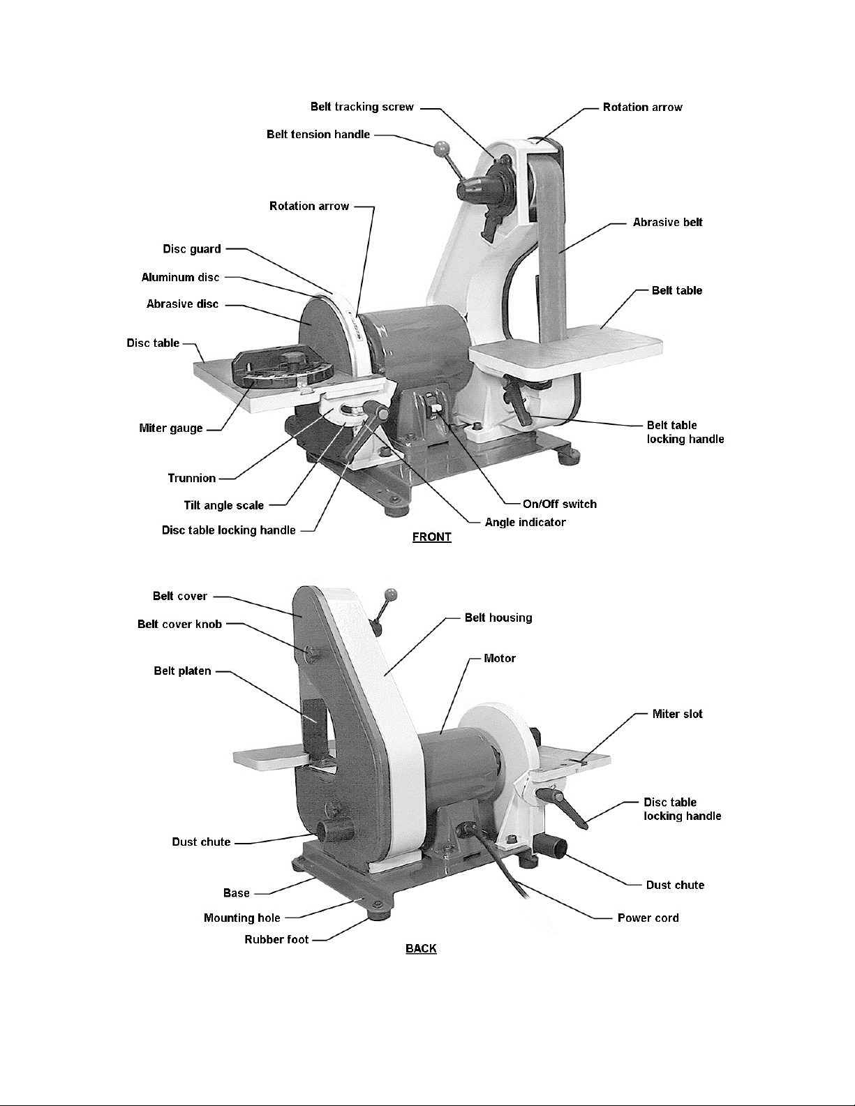
Features and Terminology
7
Page 8
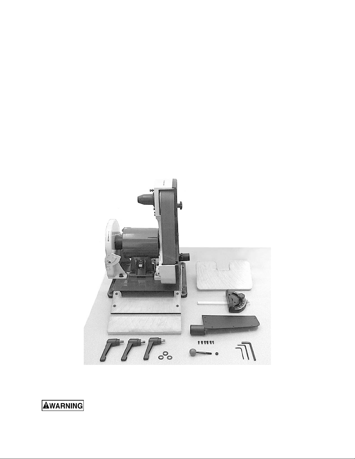
Unpacking
Open shipping cont ainer and check f or shipping
damage. Report any damage immediately to
your distributor and shipping agent. Do not
discard any shippi ng material until t he sander is
assembled and running properly.
Compare the c ontent s of y our cont ainer wit h t he
following parts list to make sure all parts are
intact. Mi ssing parts, i f any, should be reported
to your distributor. Read the instruction manual
thoroughly for assembly, maintenance and
safety instructions.
Contents of the Shipping Container
1 Belt and Disc Sander
1 Belt Table
1 Disc Table with trunnions
1 Miter Gauge
1 Dust Chute
6 Phillips Pan Hd. Machine Screws, 3/16x3/8”
3 Handles
3 Flat Washers, 3/8”
1 Tension Handle
1 Hex Nut, 1/4”
3 Hex Wrenches, 3, 4 and 6mm
1 Owner's Manual
1 Warranty Card
Read and understand the entire contents of this manual before attempting set-up
or operation! Failure t o co mply may cause serious injury.
8
Page 9

Assembly
Tools needed for assembly:
• 10mm open-end wrench
• Cross-point (P hillips) screwdriver
• Combination square, or similar angle
measuring devic e.
Sander must be unplugged
from power source during assembl y.
Remove the pr otective coating from the surf ac es
of the sander and from any loose parts. This
coating may be removed with a soft cloth
moistened with kerosene (do not use acetone,
gasoline or lacquer thinner for this purpose).
After cleaning, cover the table surfaces with a
good quality paste wax.
Leave enough space aroun d the sander f or l ong
workpieces and for gener al maintenance.
If needed, the sander c an be bolt ed to a t abl e or
workbench using the holes in the base. If the
sander has a tendency to walk or slide during
operation, it must be bolted to a supporting
surface.
Installing Belt Table
1. Unscrew the stud. See Figur e 1.
2. Position the brac k et of the belt table over the
holes in the ca sting as sh own, and re-i nstal l
the stud into its hole.
3. Place a flat washer onto a handle, and insert
the handle through the table bracket and
into the hol e. Screw the handle all the way
into the hole.
NOTE: The handle i s spring loaded; screw
the handle in by rot ating cloc kwise, then pul l
outward on the handle. Rotate the handle
back to position, then release it, making sure
it seats itself upon the pin. Continue the
process until the handle is tightened in the
hole.
Installing Dust Chute
The sander has two 1- 1/2” diam eter dust chutes.
The dust chute for the belt is locat ed on the belt
cover. The dust chute for the disc should be
install ed as shown in Figure 2, using the six (6)
pan head machine screws that ar e pr ov ided.
Figure 1
The dust chutes can be connect ed to a vacuum
system to collect dust particles.
Figure 2
9
Page 10

Installing Disc Table
1. Position the disc table at an angle, as shown
in Figure 3, and sli de the table on so that the
trunnion slots fit over the raised tracks on
the disc guard.
2. Install a flat washer onto each of the two
remaini ng handles. Insert the handle into the
holes through the left and right trunnions.
See Figure 4.
3. The gap between the sanding di sc and the
disc table sho uld be a m aximum of 1/ 16”. If
it is larger than this, loosen the two socket
head cap screws on the disc guard (one is
shown in Fi gure 4) and sli de the disc guard
to achieve this gap m easurement.
4. When finished, tighten the two socket head
cap scre ws securely.
Figure 3
Installing Miter Gauge
Insert the miter gauge bar into one end of the
miter slot in the disc table. See Figure 5.
The mit er gauge can be used in eit her directi on
in the slot to achieve the most effective
positioning of the workpiece against the abrasive
disc.
Installing Tension Handle
1. Place the 1/4” hex nut onto the threads of
the tension handl e.
2. Screw the tension handle into the hole on
the hub, then ti ght en the hex nut against the
hub. See Figure 6.
Figure 4
Figure 5
Figure 6
10
Page 11

Grounding Instructions
This machine must be
grounde d while in use to protect the ope r a t or
from electri c sho ck.
In the event of a malfunction or breakdown,
grounding prov i des a path of least resistanc e f or
electric current to reduce the risk of electric
shock. This tool is equipped with an electric cord
having an equipment-grounding conductor and a
grounding plug. The plug must be inserted into a
matching receptacle that is properly installed
and grounded in acc orda nce with al l l ocal codes
and ordinances.
Do not modify the pl ug pr ovided. If it will not fit
the outlet , have the proper outlet i nstalled by a
qualified elec trician.
Improper connection of the equipmentgrounding conductor can result in a risk of
electric shock. The conductor, with insulation
having an outer surface that is green with or
without yellow stripes, is the equipmentgrounding conduct or. If repair or replacement of
the electric cord or plug is necessary, do not
connect the equipment-gr ounding conductor t o a
live terminal.
Check with a qualified electrician or service
personnel if the grounding instructions are not
completely understood, or if in doubt as to
whether the tool is properl y grounded. Use onl y
three wire ex tension cords that have three-pr ong
grounding plugs and t hree-pole recept acles that
accept the tool ’s pl ug.
115 Volt Operation
As received from the factory, your sander is
ready to run at 115 volt oper ation. This sander is
intended for use on a circuit that has an outlet
and a plug that looks like the one illustrated in
Figure 7.
A temporary adapt er, like the adapter i n Figure
8, may be used to connect this plug to a twopole receptacle, as shown in Figure 8, if a
properly grounded outlet is not available. The
temporary adapter should only be used until a
properly grounded outlet can be installed by a
qualified electrician. This adapter is not
applicable in Canada. The green colored rigi d
ear, lug, or tab, extending from the adapter,
must be connect ed to a permanent ground such
as a properly gr ounded outlet box, as shown in
Figure 8.
Figure 8
Extens ion Cords
Use proper ext ension cor ds. Make sur e the cor d
rating is suitable for the amperage of the
machine’s mot or. An undersized cord will cause
a drop in line voltage r esulting i n loss of power
and overheating.
Use the chart in F igure 9 as a general gui de in
choosing the correc t size cord. The smaller the
gauge number, the heavier the cord.
Recommended Gauges (AWG ) of Extension Cords
Extension Cord Length *
25
50
75
100
150
200
feet
feet
feet
feet
feet
Amps
< 5 16 16 16 14 12 12
5 to 8 16 16 14 12 10 NR
feet
8 to 12 14 14 12 10 NR NR
12 to 15 12 12 10 10 NR NR
15 to 20 10 10 10 NR NR NR
21 to 30 10 NR NR NR NR NR
*based on li miting th e lin e vol tage drop to 5V at 15 0% of t h e
rated amp eres.
NR: Not Recommended.
Figure 7
Figure 9
11
Page 12

Adjustments
Tilting the Belt Table
The belt table til ts from zero ( horizont al) down to
45°.
1. Loosen the handle and adjust t he table into
desired positi on.
2. Check the angle with a machinist’s
protractor or similar measuring device that
has the required angle. Figure 10 shows a
square being used to confirm the zero, or
horizontal, positi on. Place the square flat on
the table and agai nst the bel t. Push against
the belt until the square is against the
platen.
3. Make any adjustment s to the table angle as
necessary until it is square with the belt.
4. Tighten the handle securely.
To avoid trapping the
workpiece or fingers between the table and
abrasive belt, the table edge should be
positioned a maximum of 1/16” from the
abrasive bel t.
Tilting the Disc Table
The disc table tilts from zero (horiz ontal) down to
45°.
1. Loosen both handles and adjust the table
until the indicator lines up with the desired
angle on the scale. It is a good idea to
confirm this angle using your angle
measuring devi ce placed flat upon the table
and against the abrasive disc.
2. Figure 11 shows a square being used to
confirm the zer o, or horizontal posi tion of the
disc table.
3. Make any necessary adjustments to the
table angle. If the table is square with the
disc but the angle indicator needs slight
adjustment, loosen the screw on the
indicator and shift the indicator as needed.
Re-tighten the screw.
4. Tighten both handles securely.
To avoid trapping the
workpiece or fingers between the table and
abrasive disc, the table edge should be
positioned a maximum of 1/16” from the
abrasive di sc.
Figure 10
Figure 11
12
Page 13

Use of the Miter Gauge
The miter gauge is used to sand accurate
angles on workpieces. When using the miter
gauge on the hori zontal table position, you c an
sand a single angl e. By tilt ing the disc t able and
using the miter gauge in combination with the
table tilted, it is possible to sand compound
angles as well.
The miter gauge rotates to 30° for bevel
sanding. Loosen t he knob and rot ate the gauge
body until the pointer li nes up with the d esired
angle on the scale.
Use a square to c onfirm that the miter gauge i s
set at 90° (perpendi c ular to the disc). See Figure
12. If slight adjustment is needed:
1. Loosen the knob.
2. Adj ust the miter gauge body unti l it is flush
with the square, and t he square i s f lush with
the disc.
3. Tighten the knob.
4. Loosen the screw on the pointer and adjust
the pointer until it aligns with 90° on the
scale.
5. Tighten the screw on the poi nter.
Belt Platen
The belt platen (Figure 13) is used to properly
support the workpi ece whi le sandi ng. T he plat en
is constructed of heavy steel to provide
adequate support.
The platen should be adjusted so it is almost
touching the back of the abrasive belt. Loosen
the socket head cap screw and adju st the pl aten
to the desired position. Tighten the screw to
secure the platen.
Figure 12
The platen can be r emoved f or operations such
as stripping, c ontour sanding, polishing or ot her
special operations. To remove the platen,
remove the socket head c ap screw and washer.
Be sure to re-install the platen to perform
operations where support of the belt is required.
Figure 13
13
Page 14

Abrasive Belt Replacement
1. Unplug the Sander from the power source.
2. Unscre w and remov e the two knobs on the
belt cover.
3. Remove the belt cover.
4. Rotate the tension handle (Figure 6) to
loosen the belt , and rem ov e the old belt from
around the wheels.
5. Install the new belt around the wheels.
IMPORTANT: Some sanding belts have a
directional arrow printed on the i nsi de of t he belt.
In these cases, t he belt m ust be install ed so the
directional arrow is in the same direction that the
machine is running. Refer to the rotation arrow
on top of the belt cover.
6. Install the belt cover and the two knobs.
7. Start the sander and check t he belt tracking
before sanding operations (See “Tracking
the Abrasive Belt”).
Tracking the Abrasive Belt
“Tracking” refers to the manner in which the
abrasive bel t is positioned on the wheel s during
operation. The belt should remain in vertical
position wit hout shifti ng to one side or the other
of the wheel. If any shifting occurs, the belt
needs to be track ed pr operl y , as follows:
1. Disconnect sander from power source.
2. Remove the side cover , and make sure the
belt is pl aced ev enly over t he center of the
wheels. Loosen the tension and re-position
the belt if necessary. Re-install the side
cover.
3. Move the belt by r otating the disc with your
hand (do not turn on the power yet).
Observe the movement of the belt on the top
wheel.
4. If the belt slips to one side or the other,
loosen the hex nut (Fi gure 14) with a 10m m
open-end wrench.
5. Rotate t he tracki ng screw (Fi gure 14) with a
5mm hex wrench. If the belt is sliding toward
the right, rotate the screw clockwise. If the
belt is sliding toward the left, rotate the
screw countercl oc k wise.
6. Continue t his procedure in sm all inc rements
until the belt is tracking properly when
moved by hand.
7. Re-connect t he sander to po wer, and cycle
the on/off switc h quic kly t o double c heck t he
tracking.
Figure 14
8. Re-connect t he sander to po wer, and cycle
the on/off switc h quic kly t o double c heck t he
tracking.
9. Make further adj ustm ents as needed.
10. Tighten the hex nut to secure the setting.
14
Page 15

Abrasive Disc Replacement
1. Unplug the sander from the power source.
2. Remove the dust cover and the disc table.
To remove the disc table, remove the
handles then til t the disc table upward while
pulling it away f r om the disc.
3. Peel off the old abr asive disc.
4. Thoroughl y clean the aluminum disc surface
using naptha or a similar non-flammable
solvent that will dr y film -free.
5. Pull the protective backing half-way off the
new abrasive disc.
6. Carefully posi tion the new abrasive disc so i t
is centered accur ately on the aluminum disc.
7. W hen accurately centered, r emove the r est
of the protective backing and press the
abrasive disc firmly against the aluminum
disc so complete adhesive contact is made.
8. Re-install dust c over and table.
9. Reconnect sander to power source.
Aluminum D isc Removal
The aluminum disc can be easily removed if
needed; for example, to facilitate cleaning the
aluminum di sc when replac ing abrasive discs.
1. Unplug sander fr om the power source.
2. Remove the disc tabl e and the dust chute.
3. Rotate the disc until the set screw is
accessible through the opening behind the
disc guard. See Fi gure 15. Y ou may need t o
loosen the socket head cap screws (see
Figure 4) on t he gu ard an d shi ft it for ward in
order to clear t he set screw.
4. Loosen the set screw with a 3mm hex
wrench, and pull the aluminum disc off the
motor shaft.
5. When re-m ounting the aluminum disc, make
sure the key is properly seated in the
keyway on the m otor shaft. Tighten t he set
screw firmly when the disc has been
mounted.
Figure 15
15
Page 16

Operation
This sander is intended for dry sanding of
metals. Do not use lubrica nts.
Do not sand or polish
magnesium; i t may creat e a fire hazard. Also,
do not sand very small or very thin
workpieces th at canno t be safely controlled.
Starting and Stopping the Sander
The on/off switch is located on the side of the
motor housing. Move the switch upward to the
ON positi on to start the sander. Move the switch
downward to the OFF position to stop the
sander.
When the sander is not being used, the switch
can be locked in OFF position to prevent
unauthorized use. Pull out the locking tab and
store in a safe pl ace. See Figure 16. The switch
will not operat e with the locking tab removed.
To use the sander, re-i nsert the locking tab.
Belt and Disc Movement
When the machine is turned on, the abrasive
belt should be moving downward and the disc
rotating clockwise. The motor is wired at the
factory for correct rotation.
The workpiece should not contact the disc or
belt during start-up. Before sanding, always
allow the motor to come up to operati ng speed,
then observe t he disc for wobble, runout, or any
unbalanced condit i on. If the disc i s not operat i ng
accurately and smoothly, stop the motor and
make repairs before attempting any sanding
operations.
Always sand on the side of the abrasive disc
that rotates downward. Sanding on the up ward
rotation side can cause the workpiece to catch
and fly out of your hands.
The table must be a maximum of 1/16” away
from the abrasive disc or belt.
Typical Operations
Figure 16
When sanding a compound angle you should
check the accur acy of your setup by sanding a
piece of scrap material before doing any finish
sanding on the actual workpiece.
Figure 17 demonstrates a basic method of
operation using the miter gauge and disc table:
1. Set the angle you wish to sand using the
scale on the miter gauge.
Figure 17
16
Page 17

2. Tighten the miter gauge securely so the
miter r eference angl e will not shif t while y ou
are sanding.
3. Place the workpiece against the miter
referenc e surf ac e and sl ide it along t he mi ter
referenc e surf ac e and into the sanding disc.
The following are just some of the many
operations that can be performed with your JET
Sander.
• Sharpening a wood chisel on the sanding
belt using a bl ock of wood. Use the bloc k of
wood to support the chisel and provide
clearance f or the chisel handle. See Figure
18. Sand a bevel in the block of wood in
order to position the block as close as
possible to the sanding belt and clamp the
block to the table.
• A cold chi sel can also be sharpened on the
belt table with the table tilted.
• Sanding alumi num on the disc unit wit h the
table tilted and using the miter gauge as a
guide. See Figure 19.
Figure 18
• Sanding outsi de curves on the belt unit wit h
the platen removed. See Figure 20.
• Polishing using a felt belt (not provided) in
place of the sanding belt.
Note: Most polishing operations are
perform ed with t he platen removed.
• Sandi ng in ti ght areas with t he sanding bel t.
See Figure 21.
Figure 19
Figure 20
Figure 21
17
Page 18

Maintenance
Before performing any
maintenance on the machine, disconnect it
from the electrical supply by pulling out the
plug or switching off the main switch.
Failure to compl y may cause seri ou s injury.
Keep the table surfaces clean and f r ee of rust. If
rust appears on the tables, use 000 steel wool
with a paste mixt ure of household amm onia and
good commercial detergent (or use a
commercial rust remover available from most
hardware stores.)
A light coat of paste wax on the tables will help
protect them from tarnish and reduce friction
between table and workpiece.
Note: Do not get pa ste wax on t he abra siv e bel t
or disc.
Check all fastener s for tightness.
Inspect the power cord; if worn, cut , or damaged
in any way, have it repl ac ed immediately.
Inspect the abrasive belt and disc. If either is
worn, replace it.
Occasionally remove the belt cover and brush
out any shavings or debris from around the
wheels.
Lubrication
All of the ball bearings are packed with grease
and sealed at the factory. They require no
further lubrication.
Replacement Parts
To order parts or reac h our service departm ent, call 1-800-274-6848, Monday throug h Friday (see our
website for business hour s: j ett ools.c om). Having t he Model Num ber and Seri al Num ber of your machine
available when you call wi ll allow us to serve you quickly and accur ately.
18
Page 19

Troubleshooting
Trouble Probable Cause Remedy
Not connected t o power source. Connect to power source.
Determine r eason for blown fuse/
Branch circuit fuse is blown or the
circuit breaker is tr ipped.
Sander will not star t.
tripped break er ( such as short circuit
or motor overload) . Correct reason for
fault. Repl ac e fuse/ r eset ci r c uit
breaker.
Voltage is too low.
Switch is defective. Replace switch.
Motor failure. Replace motor.
Motor stalls easily. Low voltage.
Abrasive disc
separates fr om
al uminum disc.
Abrasive belt will not
track correctly.
Improper bond.
Belt not cent er ed on wheels. Readjust track ing. See page 14.
Belt stretched unevenly. Replace abrasive belt.
Belt is jointed impr oper ly.
Wheel is worn. Replace affect ed wheel.
Worn bearings.
Check power source f or pr oper
voltage.
Check power source f or pr oper
voltage and correct if necessary.
Clean residual adhesive from
aluminum di sc, and re-apply
adhesive- bac ked abrasive disc.
Check the belt for an irr egular seam
or shape. Replace if needed.
Check all the beari ngs for ex c essive
heat or loose shafts. Replace if
necessary.
Abrasive belt slips or
stalls when pressure
is applied.
Frequent
replacement of
abrasive belt or disc.
Abrasive belt t ensi on inadequate;
spring in tensi on m ec hanism is worn.
Excessive pressure being applied to
platen.
Too much pressure being appl ied to
workpiece.
Full width of belt or di sc not bei ng
used.
Incorrect abr asive material or grit
size.
Replace spring.
Reduce pressure on abrasive belt
(and platen).
Allow the belt to do the cutti ng.
Excessive pressure only dulls the grit
and removes it from the cloth.
Stroke across abrasive belt using full
width of belt surfac e.
Check with your abrasives supplier for
recommendations on the type and
coarseness of the abrasive required
for your parti c ular workpieces.
19
Page 20

Assembly Drawing
20
Page 21

Parts List
Index No. Part No. Description Size Qty
1 ............... J-41002-01 ..............Base ...................................................................................................... 1
2 ............... TS-0680042 .............Flat Washe r ........................................................3/8”............................. 2
3 ............... TS-1551031 .............Lock Washer ......................................................M5 .............................. 4
4 ............... TS-1515041 .............Socket Head Cap Screw .....................................M8x30 ........................ 4
5 ............... TS-0050021 .............Hex Cap Sc re w ..................................................1/4-20x5/8” ................. 4
6 ............... TS-0720081 .............Lock Washer ......................................................5/16 ” ........................... 4
7 ............... 41002-07 .................Rubber Foot .......................................................................................... 4
8 ............... TS-0680021 .............Flat Washe r ........................................................1/4”............................. 4
9 ............... TS-0570011 .............Hex Nut ..............................................................1/4”-20........................ 4
10 ............. TS-1525021 .............Socket Set Screw ...............................................M10x12 ...................... 1
11 ............. 41002-11 .................Capacitor Cap ....................................................................................... 1
12 ............. 41002-12A ...............Capacitor ............................................................30uF, 300V ................. 1
13 ............. HBS814GH-166-5 ....Cross Head Flat Screw .......................................10-24x3/8” .................. 6
14 ............. 41002-14 .................Capacitor Clamp ................................................................................... 1
15 ............. TS-0570011 .............Hex Nut ..............................................................1/4”-20........................ 4
16 ............. TS-0720071 .............Lock Washer ......................................................1/4”............................. 4
17 ............. TS-1504051 .............Socket Head Cap Screw .....................................M8x25 ........................ 4
18 ............. 41002-18 .................Strain Relief Plate .................................................................................. 1
19 ............. 41002-19 .................Strain Relief ........................................................6N-4 ........................... 1
20 ............. 41002-20 .................Line Cord .............................................................................................. 1
22 ............. 41002-22 .................Strain Relief Bushing ............................................................................. 1
23 ............. 41002-23 .................Self Tapping Screw ............................................10-24 X3/8 ” ................. 2
24 ............. J-41002-24 ..............Motor Housing Base .............................................................................. 1
24A .......... J-41002-24A1
25 ............. 41002-25 .................Switch with Key ..................................................................................... 1
26 ............. 41002-26 .................Copper Washer ..................................................................................... 1
27 ............. TS-081C022 ............Phillips Pan Head Machine Screw ......................10-24x3/8” .................. 1
28 ............. TS-1540031 .............Hex Nut ..............................................................M5 .............................. 4
29 ............. J-41002-29 ..............End Shield ............................................................................................. 2
30 ............. BB-6203ZZ ..............Bearing...............................................................6203ZZ....................... 2
31 ............. 41002-31 .................Motor Fan .............................................................................................. 1
32 ............. 41002-32 .................Armatu re ............................................................................................... 1
33 ............. 41002-33 .................Stator .................................................................................................... 1
34 ............. 41002-34 .................Pan Head Screw ................................................1/4-20x7/8” ................. 4
35 ............. J-41002-35 ..............Motor Housing ....................................................................................... 1
36 ............. 41002-36 .................Pan Head Screw ................................................M5x0.8x163 ................ 4
37 ............. 41002-37 .................Bar ........................................................................................................ 1
38 ............. 41002-38 .................Pointer ................................................................................................... 1
39 ............. HBS814GH-200 .......Phillips Pan Head Machine Screw ......................1/4x3/8” ...................... 1
40 ............. 41002-40 .................Miter Body ............................................................................................. 1
41 ............. 41002-41 .................Knob ..................................................................................................... 1
42 ............. TS-2361081 .............Lock Washer ......................................................M8 .............................. 2
43 ............. 41002-43 .................Miter Gauge Assembly (includes index 37 thru 41, 99, 100) ................... 1
44 ............. TS-1534052 .............Phillips Pan Head Machine Screw ......................M6x15 ........................ 4
45 ............. J-41002-45 ..............Disc Table ............................................................................................. 1
46 ............. 41002-46 .................Armatu re Gu a r d ..................................................................................... 1
47 ............. 41002-47 .................Handle................................................................................................... 3
48 ............. J-41002-48 ..............Right Trunnion
49 ............. J-41002-49 ..............Disc Guard ............................................................................................ 1
50 ............. TS-1540061 .............Hex Nut ..............................................................M8 .............................. 4
51 ............. 41002-51 .................Alumin u m Disc ...................................................8" ............................... 1
52 ............. 6291479...................Key.....................................................................5x5x30 mm.................. 1
53 ............. 5640211...................Abrasive Disc, 100 grit ........................................8” ............................... 1
54 ............. 41002-54 .................Dust Chute. ........................................................................................... 1
55 ............. J-41002-55 ..............Left Trunnion ......................................................................................... 1
56 ............. TS-1523011 .............Socket Set Screw ...............................................M6x6 .......................... 1
..........Motor Assembly ..................................................115V, 1P h .................. 1
....................................................................................... 1
21
Page 22

Parts List
57 ............. TS-1505021 .............Socket Head Cap Screw .....................................M10x20 ...................... 2
58 ............. J-41002-58 ..............Belt Housing .......................................................................................... 1
59 ............. TS-0680031 .............Flat Washer ........................................................5/16” ........................... 4
60 ............. TS-0570011 .............Hex Nut ..............................................................1/4”-20........................ 1
61 ............. TS-1490021 .............Hex Cap Screw .................................................M8x16 ........................ 2
62 ............. TS-0680031 .............Flat Washer ........................................................5/16” ........................... 3
63 ............. 41002-63 .................Belt Table Bracket ................................................................................. 1
64 ............. J-41002-64 ..............Belt Table .............................................................................................. 1
65 ............. TS-1524031 .............Socket Set Screw ...............................................M8 x12 ........................ 1
66 ............. 41002-66 .................Shaft ..................................................................................................... 1
67 ............. BB-6202ZZ ..............Bearing...............................................................6202ZZ....................... 4
68 ............. 41002-68 .................Idler Wheel ............................................................................................ 2
69 ............. 5640491...................Retaining Ring ....................................................S-15 ........................... 2
70 ............. 41002-70 .................Abrasive Belt ......................................................100 Grit 2”x42” ........... 1
71 ............. 41002-71 .................Stand Off ............................................................................................... 2
72 ............. 41002-72 .................Drive Wheel ........................................................................................... 1
73 ............. TS-1523031 .............Socket Set Screw ...............................................M6 x10 ........................ 1
74 ............. 41002-74 .................Belt Cover ............................................................................................. 1
75 ............. 41002-75 .................Knob ..................................................................................................... 2
76 ............. 41002-76 .................Track in g Wheel Cam Shaft .................................................................... 1
77 ............. 5513018...................Retaining Ring ....................................................S-17 ........................... 1
78 ............. 41002-78 .................Tension Spring ...................................................................................... 1
79 ............. 41002-79 .................Spring Cap ............................................................................................ 1
80 ............. 41002-80 .................Handle with Knob .................................................................................. 1
81 ............. 41002-81 .................Tracking Bracket ................................................................................... 1
82 ............. TS-1540041 .............Hex Nut ..............................................................M6 .............................. 1
83 ............. TS-1503051 .............Socket Head Cap Screw .....................................M6x20 ........................ 1
84 ............. 41002-84 .................Spring Plate ........................................................................................... 2
85 ............. TS-1502021 .............Socket Head Cap Screw .....................................M5x10 ........................ 2
86 ............. TS-1502031 .............Socket Head Cap Screw .....................................M5x12 ........................ 2
87 ............. 41002-87 .................Belt Platen ............................................................................................. 1
88 ............. TS-1504031 .............Socket Head Cap Screw .....................................M8x16 ........................ 1
89 ............. TS-152707 ...............Hex Wrench .......................................................M6 .............................. 1
90 ............. TS-152705 ...............Hex Wrench .......................................................M4 .............................. 1
91 ............. TS-152704 ...............Hex Wrench .......................................................3mm x140L ................. 1
92 ............. TS-0680031 .............Flat Washer ........................................................5/16” ........................... 4
93 ............. 41002-93 .................Pan Head Screw ................................................10-24x1/4” .................. 3
94 ............. 41002-94 .................Serra te d Was h e r ...............................................M 5 .............................. 1
95 ............. 41002-95 .................Cable ................................................................. 18# 100m/m ............... 1
96 ............. 41002-96 .................Term inal .............................................................A-3 ............................. 1
97 ............. 41002-97 .................Cable ................................................................. 22# 200m/m ............... 1
98 ............. TS-0267041 .............Socket Set Screw ...............................................1/4-20x3/8” ................. 1
99 ............. TS-1550031 .............Flat Washer ........................................................M5 .............................. 1
100 ........... TS-0680022 .............Flat Wash er ........................................................1/4”............................. 1
101 ........... 41002-101 ...............Indicator ................................................................................................ 1
102 ........... 41002-93 .................Pan Head Screw ................................................10-24x1/4” .................. 1
22
Page 23

Notes
23
Page 24

427 New Sanford Road
LaVergne, Tennessee 37086
Ph.: 800-274-6848
www.jettools.com
24
 Loading...