

Page 1

This .pdf document is bookmarked
Operating Instructions and Parts Manual
Ferrous Manual Cold Saws
Models J- FK350-2, J-FK3 50 -4
WALTER M EIE R (Manufac turing) Inc.
427 New Sanford Road
LaVergne, Tennessee 37086 Part No. M-414214
Ph.: 800-274-6848 Revision B 02/2011
www.waltermeier.com Copyright © 2011 Walter Meier (Manufacturing) Inc.
J-FK350
Page 2
Warranty and Service
Walter Meier (Manufacturing) Inc., warrants every product it sells. If one of our tools needs service or repair, one of
our Authorized Service Centers located throughout the United States can give you quick service. In most cases, any
of these Walter Meier Authorized Service Centers can authorize warranty repair, assist you in obtaining parts, or
®
perform routine maintenance and major repair on your JET
your area call 1-800-274-6848.
MORE INFORMATION
Walter Meier is consistently adding new products to the line. For complete, up-to-date product information, check with
your local Walter Meier distributor, or visit waltermeier.com.
WARRANTY
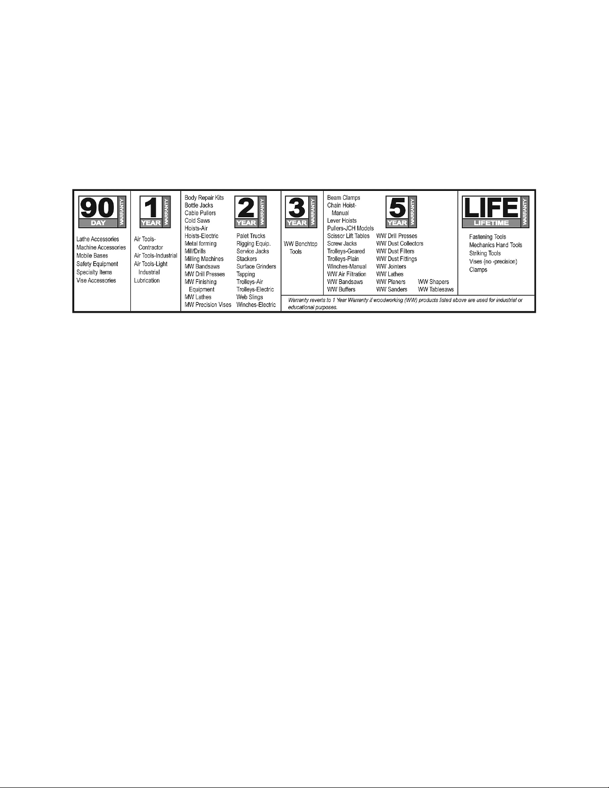
JET products carry a limited warranty which varies in duration based upon the product (MW = Metalworking, WW =
Woodworking).
WHAT IS COVERED?
This warranty covers any defects in workmanship or materials subject to the exceptions stated below. Cutting tools,
abrasives and other consumables are excluded from warranty coverage.
WHO IS COVERED?
This warranty covers only the initial purchaser of the product.
WHAT IS THE PERIOD OF COVERAGE?
The general JET warranty lasts for the time period specified in the product literature of each product.
WHAT IS NOT COVERED?
Five Year Warranties do not cover woodworking (WW) products used for commercial, industrial or educational
purposes. Woodworking products with Five Year Warranties that are used for commercial, industrial or education
purposes revert to a One Year Warranty. This warranty does not cover defects due directly or indirectly to misuse,
abuse, negligence or accidents, normal wear-and-tear, improper repair or alterations, or lack of maintenance.
HOW TO GET SERVICE
The product or part must be returned for examination, postage prepaid, to a location designated by us. For the name
of the location nearest you, please call 1-800-274-6848.
You must provide proof of initial purchase date and an explanation of the complaint must accompany the
merchandise. If our inspection discloses a defect, we will repair or replace the product, or refund the purchase price,
at our option. We will return the repaired product or replacement at our expense unless it is determined by us that
there is no defect, or that the defect resulted from causes not within the scope of our warranty in which case we will,
at your direction, dispose of or return the product. In the event you choose to have the product returned, you will be
responsible for the shipping and handling costs of the return.
HOW STATE LAW APPLIES
This warranty gives you specific legal rights; you may also have other rights which vary from state to state.
LIMITATIONS ON THIS WARRANTY
WALTER MEIER (MANUFACTURING) INC., LIMITS ALL IMPLIED WARRANTIES TO THE PERIOD OF THE
LIMITED WARRANTY FOR EACH PRODUCT. EXCEPT AS STATED HEREIN, ANY IMPLIED WARRANTIES OR
MERCHANTABILITY AND FITNESS ARE EXCLUDED. SOME STATES DO NOT ALLOW LIMITATIONS ON HOW
LONG THE IMPLIED WARRANTY LASTS, SO THE ABOVE LIMITATION MAY NOT APPLY TO YOU.
WALTER MEIER SHALL IN NO EVENT BE LIABLE FOR DEATH, INJURIES TO PERSONS OR PROPERTY, OR
FOR INCIDENTAL, CONTINGENT, SPECIAL, OR CONSEQUENTIAL DAMAGES ARISING FROM THE USE OF
OUR PRODUCTS. SOME STATES DO NOT ALLOW THE EXCLUSION OR LIMITATION OF INCIDENTAL OR
CONSEQUENTIAL DAMAGES, SO THE ABOVE LIMITATION OR EXCLUSION MAY NOT APPLY TO YOU.
Walter Meier sells through distributors only. The specifications in Walter Meier catalogs are given as general
information and are not binding. Members of Walter Meier reserve the right to effect at any time, without prior notice,
those alterations to parts, fittings, and accessory equipment which they may deem necessary for any reason
®
whatsoever. JET
branded products are not sold in Canada by Walter Meier.
tool s. F or th e nam e of an Aut hori zed Ser vic e Cent er in
2
Page 3

Table of Contents
Warranty and Servic e .............................................................................................................................. 2
Table of Contents .................................................................................................................................... 3
Warnings ................................................................................................................................................. 4
Introduction ............................................................................................................................................. 6
FK350 Featur es ................................................................................................................................... 6
Specifica tions .......................................................................................................................................... 6
Cutting Capacity (All Models) ............................................................................................................... 6
Features .................................................................................................................................................. 7
Miter Cutting Head ............................................................................................................................... 7
Miter Position Lock ............................................................................................................................... 7
Self-ce n te rin g Vise ............................................................................................................................... 7
J-FK350 Contr ols ................................................................................................................................. 7
Trigger Handle ..................................................................................................................................... 7
Flood Coolant Sy stem .......................................................................................................................... 7
Installation ............................................................................................................................................... 8
Unpacking the machine ........................................................................................................................ 8
Anchoring and handli ng the machine .................................................................................................... 8
Electric al Connec tions ............................................................................................................................. 8
Controls ................................................................................................................................................... 8
Control Panel ....................................................................................................................................... 8
Trigger Handle ..................................................................................................................................... 8
Operation ................................................................................................................................................ 9
Miter Adjustment .................................................................................................................................. 9
Depth Stop ........................................................................................................................................... 9
Maintenance .......................................................................................................................................... 10
Maintenance Requirements ................................................................................................................ 10
Periodic Maintenance ......................................................................................................................... 10
Coolan t .............................................................................................................................................. 10
Changing the Saw Blade .................................................................................................................... 1 0
Lubrication ......................................................................................................................................... 10
Coolant System.................................................................................................................................. 10
Blade Selection ..................................................................................................................................... 11
Troubleshooting ..................................................................................................................................... 14
Parts ......................................................................................................................... ............................ 1 5
Ordering Replacement Parts .............................................................................................................. 15
Head Assembly .................................................................................................................................. 16
Stock Stop Assembly ......................................................................................................................... 18
Stand Assembly ................................................................................................................................. 19
Base Assembly .................................................................................................................................. 20
Manual Vise Assembly ....................................................................................................................... 22
Guard Assembly ................................................................................................................................ 24
In-Feed Table A ssembly .................................................................................................................... 26
Out-Feed Table .................................................................................................................................. 2 7
Wiring Diagram ...................................................................................................................................... 28
3
Page 4

Warnings
1. Read and understand the entire owner's manual before att empting assembly or operation.
2. Read and understand the warnings po sted on the m achine and i n thi s manual. Failur e to comply wit h
all of these warnings m ay cause seriou s i njury.
3. Replace the warning labels if they become obscured or removed.
4. The cold saw is designed and intended for use by properly trained and experienced personnel onl y. If
you are not familiar with t he proper and safe operation of a cold saw, do not use until proper training
and knowledge have been obtained.
5. Do not use this cold saw for other than its intended use. If used for other purposes, Walter Meier
(Manufactur ing) Inc., di sclaims any real or implied warranty and hol ds itself harmless from any injur y
that may result from that use.
6. Always wear approved safety glasses/face shields while using this cold saw. Everyday eyeglasses
only have impact resi stant lenses; they are not safety glasses.
7. Before operating the cold saw, remove tie, rings, watches and other jewelry, and roll sleev es up past
the elbows. Remove all loose cl othing and c onfine long hair. Non-sl ip foot wear or anti-ski d floor strips
are recommended. Do not wear gloves.
8. Wear ear protector s (plugs or muffs) during extended periods of operation.
9. Some dust created by power sanding, sawing, grinding, drilling and other construction activities
contain chemi cals known to cause cancer , birt h defects or other repr oductiv e harm. Some examples
of these chemic als are:
• Lead from lead based paint.
• Crystalline sil ic a from bricks, cement and other masonry produc ts.
• Arsenic and chromium from chemically treated lumber.
10. Your risk of exposure varies, depending on how often you do this type of work. To reduce your
exposure to these chemicals, work in a well-ventilated area and work with approved safety
equipment, such as face or dust masks that are specifically designed to filter out microscopic
particles.
11. Do not oper ate this machine while tired or under the influence of drugs, alcohol or any medication.
12. Make c er tain the switch is in the OFF position before connecting the machine to the power supply.
13. Make c er tain the machine is properly grounded.
14. Make all machine adjustments or mai ntenance with the machine unplugged from the power source.
15. Remove adjusting keys and wrenches. Form a habit of checking to see that keys and adjusting
wrenches are removed from the machine before turning it on.
16. Keep safety guards in place at all times when the machine is in use. If removed for maintenance
purposes, use ext r eme caution and replace the guards immediat ely .
17. Make sure t he c old saw is firmly placed on a secure foundation.
18. Check damaged parts. Before further use of the machine, a guard or other part that is damaged
should be carefully checked to determine that it will operate properly and perform its intended
function. Check for alignment of moving part s, binding of moving parts, break age of parts, mounting
and any other conditions that may affect its operation. A guard or other part that is damaged should
be properly repaired or replaced.
19. Prov ide for adequate space surrounding work area and non-glare, overhead lighting.
20. Keep t he floor around the machine clean and free of scrap mater ial, oil and grease.
21. Keep visitors a safe distance from the work area. Keep ch il dren away.
22. Make y our workshop chi ld proof with padlocks, m aster switc hes or by r em ov ing starter keys.
4
Page 5

23. Giv e your work undivided attention. Looking around, carrying on a conversation and “horse-play” are
careless acts that can result in serious injury.
24. Maintain a balanced stance at all times so that you do not fall into the blade or other m ov ing par ts. Do
not overreach or use excessive force to perform any machine operation.
25. Use the right tool at the correct speed and f eed rate. Do not for ce a tool or attachm ent to do a j ob for
which it was not designed. T he ri ght tool will do the job better and safer.
26. Use recommended accessories; im pr oper accessories may be hazardous.
27. Maintain tools with care. Keep saw blades sharp and clean for the best and safest performance.
Follow instructions for lubricating and changing accessories.
28. Turn off the machine bef ore cleaning. Use a brush or compr essed air to remove chips or debri s — do
not use your hands.
29. Do not stand on the machine. Serious injury c ould oc c ur if the mac hine tips over.
30. Never leave the machine runni ng unattended. Turn the power off and do not leave the machine until it
comes to a complete stop.
31. Remove loose items and unnecessary work pieces from the area before starting the mac hine.
Familiarize you rself with the following safety notices used in this manual:
This means that if precautions are not heeded, it may result in minor injury and/or
possible machine damage.
This means that if precautions are not heeded, i t may result in serious inj ury or possibly
even death.
The specifications in this manual are given as general information and are not binding. Walter Meier
(Manufacturing) Inc., reserves the right to effect, at any time and without prior notice, changes or
alterations to par ts, fittings, and accessory equipment deemed necessary for any reason whatsoever.
5
Page 6
Introduction
The J-FK350 circ ular saw is designed to provide a reliable solution to the needs of machine shops and
production envi ronments that work wit h steel or iron. The J-FK350 i s manually operated. Aft er clamping
the material in the vise, the operator presses the trigger handle starting the blade, and brings the
operating l ev er downward to cut the material. The saw can perf orm miter c uts up to 45º to the right or left.
FK350 Features
J-FK350 Cold Saw
Specifications
Model......................................................................... J-FK350-2............................................. J-FK350-4
Stock Number .............................................................. 414214.................................................. 414217
Disc Blade
Disc diameter ...................................................... 14" (350mm).......................................... 14" (350mm)
Hole diameter ........................................................1.3" (32mm)........................................... 1.3" (32mm)
Blade thickness .................................................... 0.1" (2.5mm).......................................... 0.1" (2.5mm)
Cutting Speed
Blade Speed (RPM) ......................................................... 44/88..................................................... 44/88
Motor
Motor ........................................................................ 2HP, 3PH............................................... 2HP, 3PH
Voltage ........................................................................ 220VAC................................................. 440VAC
Other
Coolant Capacity ............................................................. 3 gal.......................................................3 gal.
Dimensions................................................ 25"L x 43"W x 75"H................................ 25"L x 43"W x 75"H
Weight .......................................................................... 720 lbs................................................... 720 lbs
Cutting Capacity (All Models)
Degree Round Square Rectangle
Tubing
Solid
90° 4.5" 4.25" 5.5" x 3.75"
45° 3.5" 3.5" 3.5" x 3.5"
90° 2" 2" 2" x 2"
45° 1.75" 1.75" 1.75" x 1.75"
6
Page 7
Features
Flood Coolant System
Miter Cutting Head
The miter cutting head is the unit that cuts the
material and c onsists of a cast i ron base, blade
support unit and guard, transmission unit, and
motor. The depth of cut is set by adjusting the
depth cut stop. The miter cutting head swivels
and locks into -45º, 90º, and +45º by means of a
locking mechanism. Depressing the mechani sm
overrides the lock, permitti ng the head to adjust
to any position between -45º and +45°.
Miter Position Lock
The miter position lock secu res th e mit er cut tin g
head from movement. The miter is secured
when the lock is pushed all the way to the left
and can be positioned when the l oc k is moved to
the right.
Self-centering Vise
The self-centering vise holds the work piece in
place during c utting. The work piece is secur ed
in the vise by turning the vise handles.
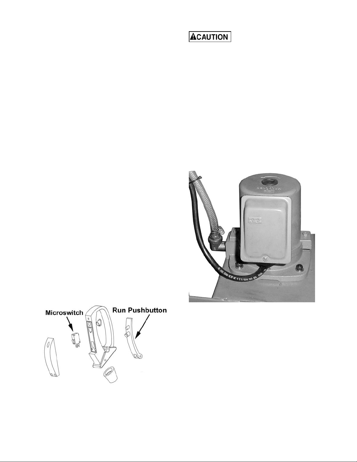
The coolant pump must be
submerged before operating to prevent
damage to the pump.
Coolant is di spensed directl y onto t he saw blade
from a coolant fitting on the upper blade guard.
Coolant is provided through tubing from the
coolant pump (Figur e 2) in the mac hine base.
Adjust the coolant flow valve on coolant fitti ng to
achieve desired fl ow. When the coolant switch is
in the ON position, flow starts when the drive
motor is started. Turning off the coolant switch
stops coolant fl ow.
This coolant system can operate with either a
soluble oil base coolant or water-soluble
synthetic coolant. Coolant should be changed
regularly. Some r ecommended brands are DoAll
and Lenox. These coolants are availabl e at your
local industrial distributor.
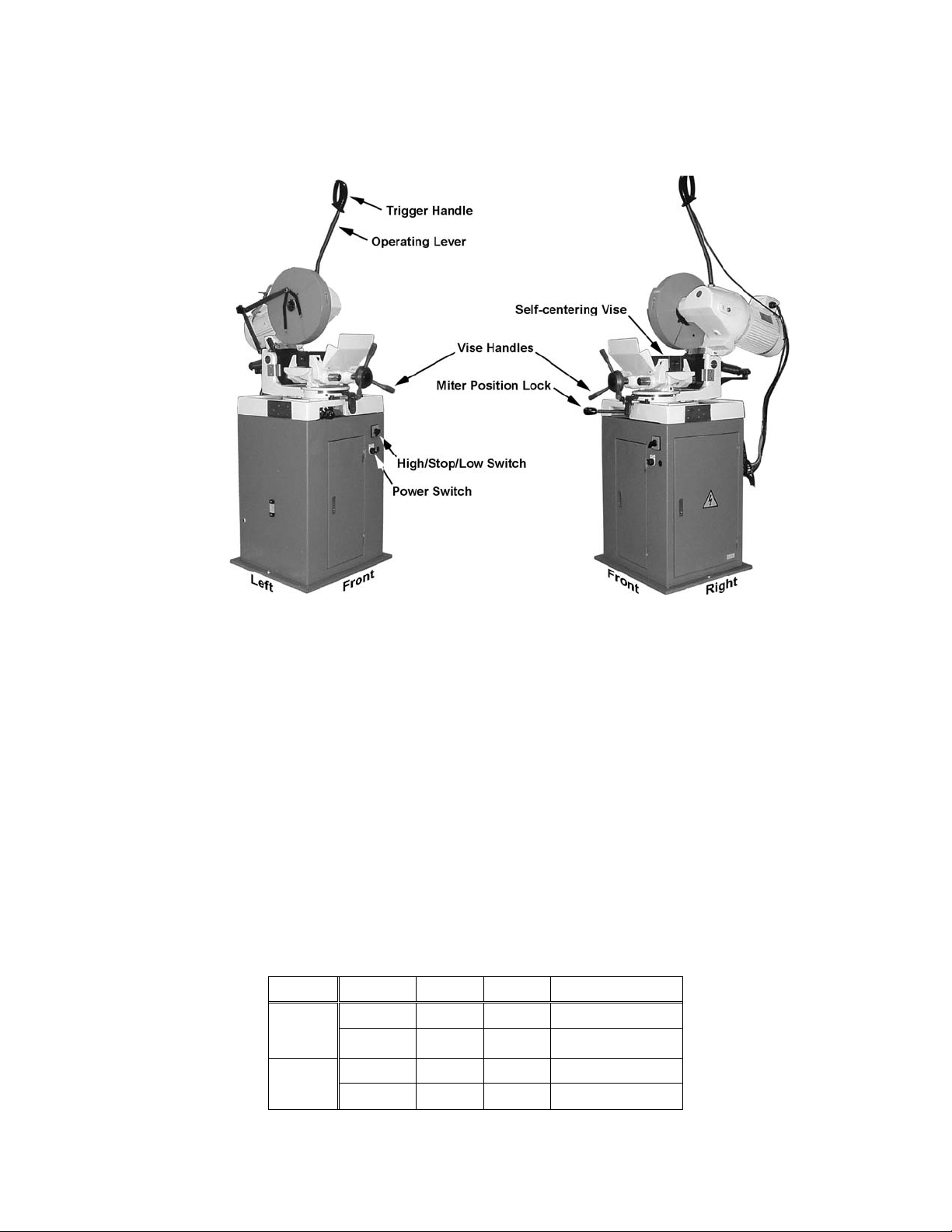
J-FK350 Controls
The cont rol panel c onsist s of the Power (On/Off)
switch and High/Stop/Low switch, and an
integral coolant system. To operate the
machine, the Power switch must be set to on
and the High/Stop/Low swi tc h m ust be se t fo r Hi
or Low. Then depr ess the tr igger handle to start.
Trigger Handle
The trigger handle (Figure 1) is located on the
operating lever used to rai se and lower the saw.
It contains a micro-switch, which is activated
when the operator depres se s the r un trigger.
Figure 2
Figure 1
7
Page 8
Installation
Controls
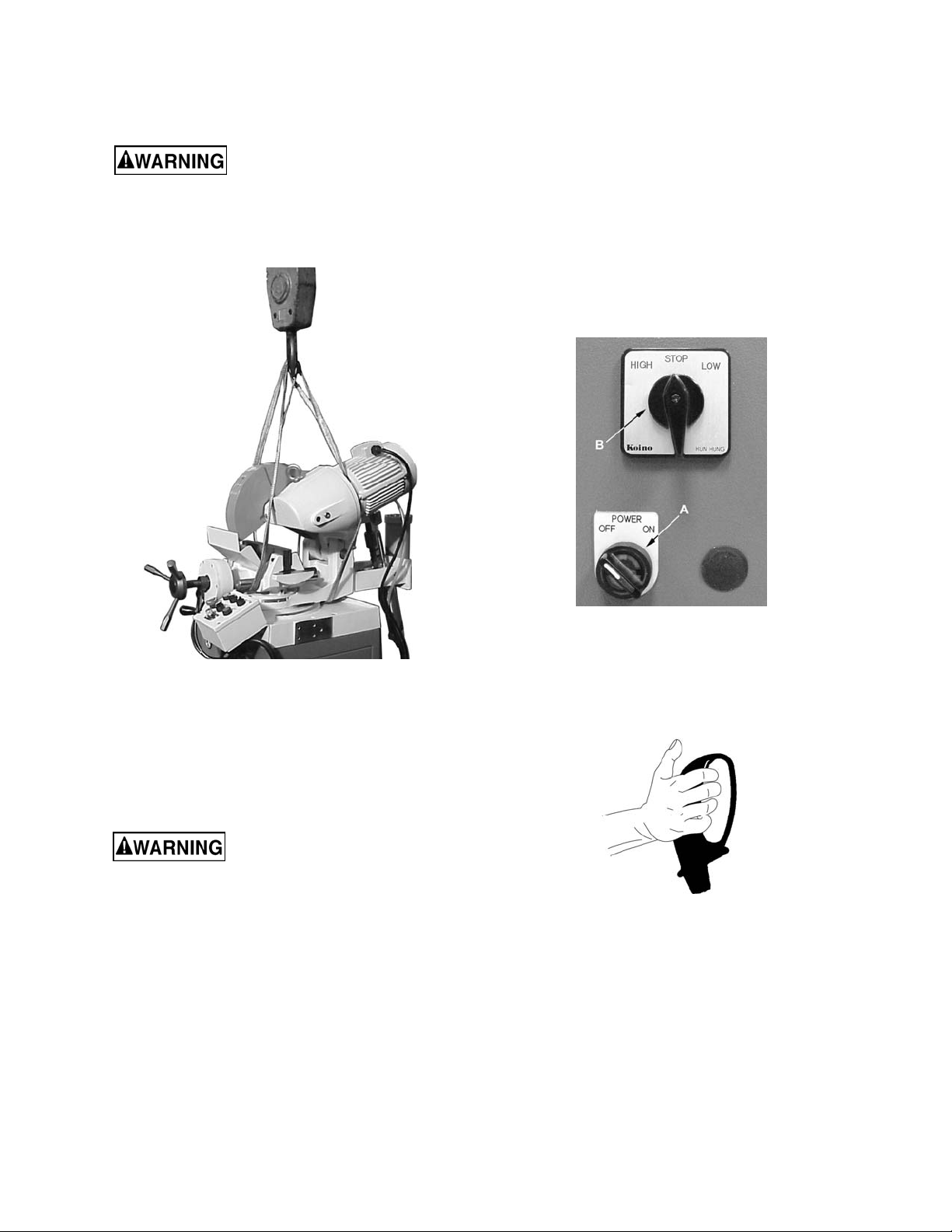
Unpacking the machine
Do not handle the packed
machine using slings.
To install t he machine, fi rst rem ove the packing,
paying particular att ention not to cut any electric
wires or hydraulic hoses. Lift using straps
(Figure 3).
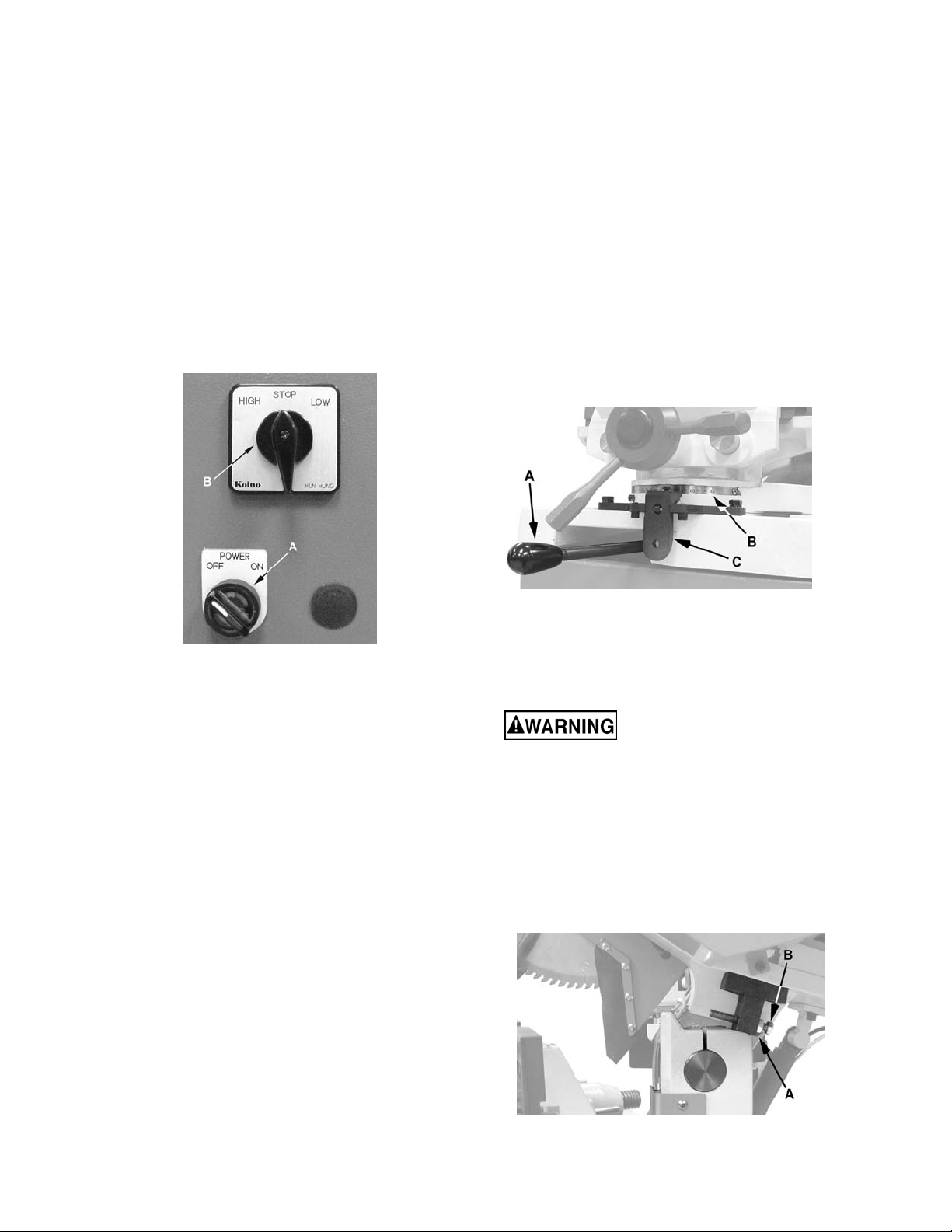
Control Panel
The Control Panel (Figure 4) is located on the
front of the cabinet stand and consists of the
Power and High/Stop/Low switches, described
below.
Power Switch – The Power switch has two
positions, Off and On.
High/Stop/Low Switch – This switch controls
the blade speed. To operat e the saw, the power
switch must set to on, High or Low must be
selected, and the Run Trigger depressed.
Figure 3
Anchoring and handling the machine
The base of the machine must be anchored to
the floor by two lag bolts or studs properly
anchored into conc r ete.
Electrical Connection s
All electrical connections
must be done by a qualified
electrician. All adjustments or repairs must
be done with the machine discon nect ed from
the power source, unplugged. Failure to
comply may result in seri ou s injury!
The J-FK350-2 is rated at 220V.
The J-FK350-4 is rated at 440V.
These machines not suppli ed with a plug. Use a
plug and outlet rated at least 20amps. The
circuit for the machi ne should al so be protected
by at least a 20 amp circuit break er or fuse.
Make sure that the blade turns in the correct
direction. If it does not, simply reverse two of
the phase wires on the supply input.
Figure 4
Trigger Handle
To operate, t he Power switch must b e set t o on
a Hi or Low speed selection made, and the
trigger handle depressed.
Figure 5
The sawing machi ne is now ready for use.
8
Page 9
Operation
Miter Adjustment
Before using the m ac hine:
Check that safety devices (e.g., blade
guards) are in position and work perfectly
and that personal safety requirements are
complied with.
Check the sharpness of the blade and verify
coolant flow.
Operation
1. Make sure the work piece is securely
clamped in the vise.
2. Turn the power on (A, Fig. 8).
3. Select the cutting speed (B , Fig. 8).
To adjust the miter position follow the steps
below while referring to Figure 10:
1. Mov e the miter position lock (A) to the right
to release.
2. Adj ust the head t o the desired angl e rangi ng
from –45º to +45º by pushing on the back of
the motor to the right or left. The miter
position is shown on the scale (B).
3. A detent mechanism locks the head in the -45º,
90º and +45º positions to pre vent the head from
rotating. For a miter position other than -45º,
90º and +45º, press the lever (C) to release
while rotating the head.
4. When the desir ed cutti ng angle is set, m ove
miter position loc k (A) to the left to secure.
Figure 8
4. Grip the trigger handle (Figure 5) on the
cont r o l lever.
5. Start the blade by pressing the micr o-switch
on the handgrip.
The down stroke speed of the head is controlled
manually by the operator. The coolant pump is
activated during t he time that the head is below
the upper limit positi on.
When the cut is complete:
6. Raise the head.
7. Rem ove the work piece from the vise using
the vise hand wheels.
Figure 10
Depth Stop
The depth cut stop ad justment limits the lower travel
of the saw blade du r ing a cutting operation.
Remove power when making
this adjustment. Failure to
comply may result in serious injury!
To adjust the depth of cut (refer to Figure 12):
1. Using t wo 13mm wrenches, loosen the lock
nut (A).
2. With the saw in the fully lowered position,
turn the screw (B) until the saw blade
bottoms out at the desir ed level.
3. Tighten the lock nut.
Figure 12
9
Page 10

Maintenance
Maintenance Requirements
All maintenance must be
carried out with the power switched off.
Failure to comply may result in serious
injury!
On completion of maintenance, ensure that
replaced parts and/or any tools used have been
removed from the machine before starting it up.
Periodic Maintenance
Remove chips from the m ac hine, preferably
with a cloth
Remove chips from the c oolant tank and
change coolant regularly (see Coolant
section)
Top up the coolant level ( see Coolant)
Check the wear of the blade and change if
necessary (see Changing the Saw Blade)
Empty the chips out of the base.
Clean the vi se and lubricate all the joints
and sliding surfac es, usi ng good quality oil.
Attend to daily, weekl y and annual
lubrication recommendations (see the
Lubrication secti on)
Coolant
The c oolant tank access door is located on the
back of the cabinet stand. Remove four hex cap
screws with a 5mm hex wrench. Check coolant
level in t he c oolant tank periodically and top off if
necessary. Coolant can also be added by
pouring directly on the table, which will drain int o
the tank through the c hip s trainer .
Lubrication
For long life and trouble-free operation, it is
essential that this machine be kept well
lubricated. The vise and leadscrew should be
oiled daily. Pivot joints and bearings should be
greased weekly. Check the gearbox oil level
weekly; full level is top of sight gl ass with head
in full up position. The gearbox oil should be
changed annually.
Recommended Lubricants:
Gearbox
Use Texaco Meropa 460 or equivalent.
Grease fittings
Texaco Star plex 2 or equivalent
Vise and Leadscrew
Regal R & O 68
Coolant System
This coolant system can operate with either a
soluble oil base coolant or water-soluble
synthetic coolant. Coolant should be changed
regularly. Some r ecommended brands are DoAll
and Lenox. These coolants are availabl e at your
local industrial distributor.
Coolant Type:
Soluble Oil Base
Water-Soluble Synthetic Coolant
Remove excess chips periodically from the tank.
Use the coolant l evel gauge to check the c oolant
level.
Changing the Saw Blade
The cold saw must not be
connected to the power source when
changing saw blad es. Failure to comply may
result in serious injury!
To change the saw blade:
1. Switch off the m achi ne.
2. Release the lower disc guard.
3. Move the lower guard upwards.
4. Remove the bl ade and replace it wit h a new
one.
5. To secure the saw blade, reverse the
preceding steps.
10
Page 11

Blade Selection
When using the J-FK350 cold saw, it is
important to sel ect the correct type of blade for
the material to be cut. Thi s section explains the
limitations and specific applications of the
different t y pes of blades.
General Characteristics:
Fine Tooth Pitch – used for thin wall materials
such as sheet steel, tubes and prof iles
Coarse Tooth Pitch – used for large crosssections – for soft materials (aluminum alloys
and soft alloys in general).
Determining Proper Tooth Pitch
Proper tooth pit c h depends on:
a) the size of the section;
b) the hardness of the m aterial;
c) wall thickness.
Solid sections call for
discs with a coarse
tooth pitch, while
small cross-sections
require blades with
finer teeth. This is
because when cutting
walls of small crosssection (1–7 mm)
profiles, it is im portant that the number of teeth
actually m aking the cut should not be too small,
otherwise the effect obtained will be one of
tearing rat her than of chip remov al, leading to a
large increase in shearing stress. On the other
hand, when cutting thick materials or solid
sections using an excessively fine tooth pitch,
the chip collects as a spiral inside the gull et, and
since fine tooth pitches have small gullets, the
accumulat ed chip will exceed the gullet capacity
and press against the walls of the workpieces,
resulting in poor cutting (same situati on with soft
materials), greater shearing stress and hence
breakage of the bl ade.
Table 1
A larger pitch should be chosen when, as a
result of the shape of the piece to be cut, the
cross-section at any given point exceeds the
average cross-sect ion given above.
Cutting and Feeding Speed
The cutting speed, in m/min, and the head
feeding speed, in cm
amount of heat generated near t he points of the
teeth. If t he head feeding speed is too hi gh, the
cut will not be straight i n either the vertic al or the
horizontal plane. As we have already said, the
cutting speed depends on the strengt h (kg/mm
and hardness (HRC) of the material and the
dimensions of the thickest section. The feeding
speed depends on the cross-section of the
material. Solid or thick-walled materials
(thickness>5mm) can therefore be cut at high
speed providi ng there is sufficient swarf rem oval
by the blade, while t hin-wall ed mat erials such as
tubes or thin profiles must be cut with a low
feeding speed.
break-in p eriod, du ring which time abou t half
the normal feeding sp eed shoul d be used.
2
/min, are limited by the
2
)
A new blade requires a
Coolant
The cooling fluid ensures that the blade teeth
and material in the area of the cut do not
overheat. The fluid must be an excellent
lubricant so as to prev ent abrasion of the teet h
and welding of t he chips to t he teet h themselv es
(seizing).
11
Page 12

Blade Structure
For non-ferrous metals, it is common to use
circular saws wit h brazed hard m etal HM cutting
edge, consisting of a disc made of alloy tool
steel (71Cr1) on which the shape of the teeth
and the seats for the cutti ng edges are made of
Widia K10. These saws have shown excellent
wear resistance but low resistance to impact,
which is in any case a minor pr oblem with nonfe rrous materials.
Table 2
Types of Blades
Figure 14
”BW” TYPE SHARPENING DIN 1838--UNI 4014
Coarse toothing with teeth alternately raked to
the right and left.
Toothing generally used on cutti ng-off machines
for cutting ferrous and alloy materials with
tubular and profil ed sect ions.
The blades fitted to the J-FK350 have
dimensions 350 x 32 x 2.5 mm and are of HM
hard steel type sinc e the machi ne is to be used
for cutting non-ferrous materials. In addition to
the size and pitch of the teeth, however, the
blades also have different geometric
characteri stic s i n accordance with thei r partic ular
use:
tooth cutting angle – may be negative or
positive
tooth sharpening –may be BW with an
alternate raked tooth or C with a roughing tooth
raked on both sides and a non--raked finishing
tooth
tooth pi tch – the distance between the crest of
one tooth and the crest of t he next toot h (tooth
pitch = T)
Teeth Shape
”C” TYPE SHARPENING (HZ)
Coarse toothing with roughing tooth raked on
both sides and non--raked finishing tooth. The
roughing tooth is about 0.3 mm higher.
Coarse toothing with roughing tooth and
finishing tooth. Used in saws with pitch greater
than or equal to 5 mm for cutting ferrous and
non-ferrous m ateri als with soli d or solid-profiled
sections.
Figure 15
POSITIVE AND NEGATIVE CUTTING ANGLES
The cutting angle may vary from positive to
negative depending on the cutting speed, the
profile and the type of m at eri al to be cut.
Figure 16
A positive angle determines bett er penetrati on of
the tool and hence lower shear stress and
greater ease of sliding for the swarf over the
cutting edge. On the other hand, the cutting
edge has lower mechanical resistance, so as the
breaking load of the material to be cut increases,
the cutting angl e decreases from positiv e until it
becomes negativ e so as to offer a cutting edge
with a larger resistant sect ion.
12
Page 13

Figure 17
Short swarf material such as brass, bronze,
aluminum and hard cast iron require smaller
cutting angles because the swarf becomes
crushed immediately and the rake angle has
little effec t during the cutting stage.
Figure 18
The J-FK350 uses discs with positive cutting
angles for cutting solid materials and with
negative cutting angles for cutting hollow
profiles. Thi s is because, as a result of the hi gh
cutting speeds (3400 rpm), even with
non-ferrous materials the tool ”strikes” against
the wall of the profile to be cut several times,
thus requiring a cutting edge with a larger
resistant section.
Figure 19
Circular saws can also be characterized by other
parameter s such as the whine r educti on f eature,
which cuts down noise at high speeds, or
expansion, which compensates for the pushing
of chips inside the cutting edge, thus reducing
the thrust on the walls of t he material to be cut.
Figure 20
13
Page 14

Troubleshooting
Troubleshooting – Blade and Cutting Problems
Problem Probable Cause Solution
Incorrect lubricant/coolant fluid Ensure proper coolant flow.
Check the cutting speed, feed speed and air pressure
parameters and the type of blade you are u sing.
With a new blade it is necessary to start cutting at half
feeding speed. After t he wear ing- - in period (a cutting
surface of about 300 cm2 for hard materials and about
1000 cm
speeds can be brought up to normal values
The s warf w edges into t he bott om of the teeth caus ing
excessive pressure on the teeth themselves
The surface of the cut may have undergone work
hardening. When starting work again, use a lower
cutting speed and head feed speed. A tooth from the
old blade may be left in the cut: check and remove
before starting work again.
Any movement of the work piece during cutting can
cause broken teeth: check the vise, jaws and clamping
pressure.
The blade runs over the material without removing it:
increase feed sp eed.
The teeth slid e over t he mater ial withou t cutting it :
reduce the blad e speed.
Check the coolant level and clean coolant lines and
nozzles.
The materials may pres ent al tered zones either on the
surface, such as oxides or sand, or in section, such as
under-cooled inclusions. These zones, which are
much harder than the blade, caus e t he teet h to br eak:
discard or clean these materials.
Always check the position of the blade before starting
a new job.
Check the coolant level and clean coolant lines and
nozzles.
Teeth breaking
Rapid to oth wear
Broken blade
Material too hard
Disc not worn-in correctly
Disc with excessively fine
tooth pitch
New blade inserted in a
partially completed cut
Work piec e not cl amped firmly
in place
Feed speed t oo slow
Cutting pressure too high Reduce cutting pressure.
Blade speed too high
Insufficient coolant
Incorrect fluid concentration Check and use the correct concentration.
Material defective
Feed speed too high Reduce blade speed.
Teeth in contact with material
before starting the cut
Insufficient coolant
2
for soft materials) the cutting and feed
14
Page 15

Troubleshooting
Troubleshooting – Machine Fault & Operating Problems
Problem Probable Cause Solution
Electrical power supply
Transformer
Contactor
Spindle motor will not
turn
Thermal relay
Motor
Check: the phases; the cables; the plug; the socket.
Also check that the motor connections are in place.
Chec k that the voltag es are present both on the input
and output. Otherwise replace.
Chec k that the phases in it are present both on the
input and output, that it is not jammed, that it closes
when powered and that it is not causing short circuits.
Change if any of these problems are found.
Make sure it is closed, i.e. check that the phases are
present in input and output, that it is not causing short
circuits and responds when the reset coil is closed. If it
has tripped to protect the motor, check the amperage
setting, reset, and check the motor. Change if
necessary.
Check that it has not burnt out, that it turns freely and
that there is no moisture in the connection terminal
board box. The winding can be rewound or replaced.
Parts
Ordering Replacement Parts
To order parts or reach our service department, call 1-800-274-6848 Monday through Friday (see our
website for business hours, www.walt ermei er.com). Hav ing the Model Number and Serial Number of your
machine avail able when you call will allow us to serve you quickly and acc ur ately.
15
Page 16

Head Assembly
Index No. Part No. Description Size Qty
1 ............... J-FK350-201 ............Head Body ............................................................................................ 1
2 ............... FK350-202A.............Spindle .................................................................................................. 1
3 ............... FK350-203 ...............Spindle Housing .................................................................................... 1
4 ............... FK350-204 ...............Cutter Cap ............................................................................................. 1
5 ............... FK350-205 ...............Cutter Cap Pin ....................................................................................... 2
6 ............... FK350-206 ...............Stopper Ring ......................................................................................... 1
7 ............... FK350-207 ...............Spring Block .......................................................................................... 1
8 ............... FK350-208 ...............Tension Bolt .......................................................................................... 1
9 ............... FK350-209 ...............Belleville Spring ..................................................................................... 4
10 ............. FK350-210 ...............Taper S haft ........................................................................................... 1
11 ............. FK350-211 ...............Wor m Wheel ......................................................................................... 1
12 ............. FK350-212 ...............Wor m Shaft ........................................................................................... 1
13 ............. FK350-213 ...............36NTGear ............................................................................................. 1
14 ............. FK350-214 ...............21NTGear ............................................................................................. 1
15 ............. FK350-215 ...............Collar A ................................................................................................. 1
16 ............. FK350-216 ...............Collar B ................................................................................................. 1
17 ............. FK350-217 ...............Bearing Cover ....................................................................................... 1
18 ............. FK350-218 ...............Handle................................................................................................... 1
19 ............. FK350-219 ...............Handl e S witch ....................................................................................... 1
21 ............. BB-32007 .................Tapered Roller Bearing .......................................#32007 ....................... 1
22 ............. BB-32008 .................Tapered Roller Bearing .......................................#32008 ....................... 1
23 ............. FK350-223 ...............Retainer ................................................................................................ 1
24 ............. FK350-224 ...............Tooth Washer ........................................................................................ 1
25 ............. FK350-225
26 ............. FK350-226 ...............Retainer Nut .......................................................................................... 1
27 ............. FK350-227 ...............Tooth Washer ........................................................................................ 1
28 ............. FK350-228 ...............Tooth Washer ........................................................................................ 1
29 ............. FK350-229 ...............Retainer Nut .......................................................................................... 1
30 ............. FK350-230 ...............Fl at Key ..............................................................8x7x42mm.................. 1
31 ............. FK350-231 ...............Fl at Key ..............................................................8x7x27mm.................. 1
32 ............. FK350-232 ...............O-Ring................................................................................................... 1
33 ............. FK350-233 ...............O-Ring................................................................P8 .............................. 1
34 ............. FK350-234 ...............Pin......................................................................5mm Dia. x 28 ............ 2
35 ............. TS-1540071 .............Hex Nut ..............................................................M10 ............................ 2
36 ............. FK350-236 ...............Needl e Roller Bearing.........................................BK3026 ...................... 1
37 ............. BB-51206 .................Thrust Bearing ....................................................#51206 ....................... 1
38 ............. BB-6206...................Deep Groove Ball Bearing ..................................#6206 ......................... 1
39 ............. J-FK350-239 ............Motor 220V ............................................................................................ 1
................. J-FK350-239-4 .........Motor 440V ............................................................................................ 1
40 ............. ................................Saw Blade ............................................................................................. 1
41 ............. FK350-241 ...............Stopper ................................................................................................. 1
42 ............. FK350-242 ...............Oil Sight Glass....................................................................................... 1
43 ............. TS-1504051 .............Socket Head Cap Screw .....................................M8x25 ........................ 2
44 ............. TS-1504041 .............Socket Head Cap Screw .....................................M8x20 ........................ 4
45 ............. TS-1504131 .............Socket Head Cap Screw .....................................M8x70 ........................ 1
46 ............. FK350-246 ...............Oil Plug ................................................................................................. 1
47 ............. FK350-247A.............Socket Head Cap Screw (left-hand thread) .........M20x45 (LH) .............. 1
48 ............. FK350-248
49 ............. FK350-249 ...............Oil Plug ................................................................................................. 1
50 ............. TS-1504061 .............Socket Head Cap Screw .....................................M8x30 ........................ 2
51 ............. TS-1492051 .............Hex Cap Screw ..................................................M1 2x50 ...................... 4
52 ............. TS-154012 ...............Hex Nut ..............................................................M20 ............................ 1
53 ............. TS-1540061 .............Hex Nut ..............................................................M8 .............................. 1
54 ............. TS-2361201 .............Lock Was h e r ......................................................M20 ............................ 1
55 ............. TS-2361121 .............Lock Was h e r ......................................................M12 ............................ 4
...............Retainer Nut .......................................................................................... 1
...............Oil Plug ................................................................................................. 1
16
Page 17

Head Assembly
17
Page 18

Stock Stop Assembly
Index No. Part No. Description Size Qty
1 ............... FK350-501 ...............Block ..................................................................................................... 1
2 ............... FK350-502 ...............Shaft ..................................................................................................... 1
3 ............... FK350-503 ...............Stop Rod ............................................................................................... 1
4 ............... FK350-504 ...............Scale (Inch) ........................................................................................... 1
6 ............... FK350-506 ...............Handle................................................................M8x30 ........................ 2
7 ............... FK350-505 ...............Rivet ...................................................................................................... 2
18
Page 19

Stand Assembly
Index No. Part No. Description Size Qty
1 ............... J-FK350-601 ............Cabinet Stand........................................................................................ 1
2 ............... FK350-602 ...............Coolant Pump........................................................................................ 1
3 ............... FK350-603 ...............Cam Switch ........................................................................................... 1
4 ............... FK350-604 ...............Magnetic Switch .................................................................................... 1
5 ............... FK350-605 ...............Overload Relay ...................................................................................... 1
6 ............... FK350-606 ...............Lighted Selector Switch ......................................................................... 1
7 ............... TS-1502051 .............Socket Head Cap Screw .....................................M5x20 ........................ 4
8 ............... TS-1551031 .............Lock Washer ......................................................M5 .............................. 4
9 ............... FK350-609 ...............Cable Lock ............................................................................................ 3
10 ............. J-FK350-610 ............Rear Cover ............................................................................................ 1
11 ............. TS-1503021 .............Socket Head Cap Screw .....................................M6x10 ........................ 4
12 ............. FK350-612 ...............Taper ed P lug ......................................................PT1/4 ......................... 1
13 ............. FK350-613 ...............Coolant Gauge ...................................................................................... 1
14 ............. TS-1502051 .............Socket Head Cap Screw .....................................M5x20 ........................ 2
15 ............. FK350-615 ...............Transformer (440V only) .....................................AU-20DW(50/60Hz) .... 1
................. FK350-615-2 ............Transformer (220V only) ........................................................................ 1
19
Page 20

Base Assembly
Index No. Part No. Description Size Qty
1 ............... J-FK350-101 ............Base ...................................................................................................... 1
2 ............... J-FK350-102 ............Hinge Body ............................................................................................ 1
3 ............... FK350-103 ...............Locking Mount ....................................................................................... 1
4 ............... FK350-104 ...............Release Handle ..................................................................................... 1
5 ............... FK350-105 ...............Pin......................................................................................................... 1
6 ............... FK350-106 ...............Coil Spring............................................................................................. 1
7 ............... FK350-107 ...............Scale ..................................................................................................... 1
8 ............... FK350-108 ...............Pivot Shaft ............................................................................................. 1
9 ............... J-FK350-109A ..........Spring Bracket A ................................................................................... 1
10 ............. J-FK350-110A ..........Spring Bracket B ................................................................................... 1
11 ............. FK350-111A.............Retur n Spring ........................................................................................ 1
12 ............. FK350-112 ...............Chip Screen .......................................................................................... 1
13 ............. TS-1505031 .............Socket Head Cap Screw .....................................M10x25 ...................... 2
14 ............. TS-1551071 .............Lock Was h e r ......................................................M10 ............................ 2
15 ............. TS-1504041 .............Socket Head Cap Screw .....................................M8x20 ........................ 2
16 ............. TS-1504101 .............Socket Head Cap Screw .....................................M8x50 ........................ 2
17 ............. TS-1491041 .............Hex Cap Screw ..................................................M1 0x30 ...................... 2
18 ............. TS-2361101 .............Lock Was h e r ......................................................M10 ............................ 2
19 ............. TS-1504021 .............Socket Head Cap Screw .....................................M8x12 ........................ 2
20 ............. TS-1490041 .............Hex Cap Screw ..................................................M8 x25 ........................ 1
21 ............. TS-223A911.............Socket Head Cap Screw .....................................M12x100 .................... 2
22 ............. FK
23 ............. FK350-123 ...............Pin......................................................................10mm Dia. x 22 .......... 3
24 ............. FK350-124 ...............Grease Fitting .....................................................PT 1/8 ........................ 2
350-122 ...............Pipe ....................................................................................................... 1
20
Page 21

Base Assembly
10
15
17
8
16
24
7
23
1
11
9
2
12
21
14
13
18
3
20
22
19
6
5
4
FK-350-BASE ASS'Y
21
Page 22

Manual Vise Assembly
Index No. Part No. Description Size Qty
................. FK350-300 ...............Complete Vise Assembly (includes index #1-32) ......................................
1 ............... J-FK350-301 ............Base ...................................................................................................... 1
2 ............... J-FK350-302 ............Front Vise Jaw....................................................................................... 1
3 ............... FK350-303 ...............Tip ......................................................................................................... 1
4 ............... FK350-304 ...............Vi se Screw ............................................................................................ 1
5 ............... FK350-305 ...............Jaw Insert A (Steel, Smooth) ................................................................. 2
FK350-305ST ..........Jaw Insert A (Steel, Serrated) ................................................................ 2
6 ............... FK350-306 ...............Jaw Insert B (Steel, Smooth) ................................................................. 2
................. FK350-306ST ..........Jaw Insert B (Steel, Serrated) ................................................................ 2
7 ............... FK350-307 ...............Guide Rod ............................................................................................. 2
8 ............... FK350-308 ...............Handle Hub ........................................................................................... 1
9 ............... FK350-309 ...............Handle................................................................................................... 3
10 ............. FK350-310 ...............Filling Block ........................................................................................... 1
12 ............. FK350-312 ...............Cap ....................................................................................................... 1
13 ............. FK350-313 ...............Setting Screw ........................................................................................ 1
14 ............. FK350-314 ...............Hex Nut ..............................................................M20x1.5P ................... 1
15 ............. J-FK350-315 ............Cover .................................................................................................... 1
16 ............. FK350-316 ...............Tension Handle ..................................................................................... 1
17 ............. FK350-317 ...............Tension Nut ........................................................................................... 1
18 ............. FK350-318 ...............Pressure Plate ....................................................................................... 1
19 ............. FK350-319 ...............Scale Centering ..................................................................................... 1
20 ............. FK350-320 ...............Pin......................................................................10mm Dia. x 30 .......... 2
21 ............. FK350-321 ...............Retainer ................................................................................................ 2
22 ............. TS-1505051 .............Socket Head Cap Screw .....................................M10x35 ...................... 4
23 ............. TS-1540071 .............Hex Nut ..............................................................M10 ............................ 4
25 ............. TS-1502031 .............Socket Head Cap Screw .....................................M5x12 ........................ 2
26 ............. TS-1550031 .............Flat Washe r ........................................................M5 .............................. 2
27 ............. TS-1490091 .............Hex Cap Screw ..................................................M8 x50 ........................ 3
28 ............. TS-1540061 .............Hex Nut ..............................................................M8 .............................. 3
29 ............. TS-1505041 .............Socket Head Cap Screw .....................................M10x30 ...................... 2
30 ............. TS-1505011 .............Socket Head Cap Screw .....................................M10x16 ...................... 2
31 ............. FK350-331 ...............Rivet ...................................................................2mm Dia. x 4 .............. 2
32 ............. J-FK350-332 ............Rear Vise Jaw ....................................................................................... 1
22
Page 23

Manual Vise Assembly
23
Page 24

Guard Assembly
Index No. Part No. Description Size Qty
1 ............... J-FK350-401 ............Guard A ................................................................................................. 1
2 ............... J-FK350-402 ............Guard B ................................................................................................. 1
3 ............... J-FK350-403 ............Guard C ................................................................................................ 1
4 ............... FK350-404 ...............Link A .................................................................................................... 1
5 ............... FK350-405 ...............Nylon Spacer A ..................................................................................... 6
6 ............... FK350-406 ...............Nylon Spacer B ..................................................................................... 3
7 ............... FK350-407 ...............Nylon Spacer C ..................................................................................... 2
8 ............... FK350-408 ...............Link B .................................................................................................... 1
9 ............... FK350-409 ...............Link C .................................................................................................... 1
10 ............. FK350-410 ...............Link Ring ............................................................................................... 1
11 ............. FK350-411 ...............Link Pin ................................................................................................ 1
12 ............. FK350-412 ...............Link Bracket .......................................................................................... 1
13 ............. FK350-413 ...............Link D .................................................................................................... 1
14 ............. FK350-414 ...............Link D Ring ............................................................................................ 1
15 ............. TS-1504031 .............Socket Head Cap Screw .....................................M8x16 ........................ 3
16 ............. TS-1550061 .............Flat Washe r ........................................................M8 .............................. 3
17 ............. TS-1504061 .............Socket Head Cap Screw .....................................M8x30 ........................ 2
18 ............. TS-1551061 .............Lock Was h e r ......................................................M8 .............................. 2
19 ............. TS-1521021 .............Set Screw ...........................................................M4x6 .......................... 1
20 ............. FK350-420 ...............Snap Ring ..........................................................S48 ............................ 1
21 ............. FK350-421 ...............Snap Ring ..........................................................S10 ............................ 2
22 ............. FK350-422 ...............Bushing ................................................................................................. 1
23 ............. FK350-423 ...............Knob ..................................................................M8x30 ........................ 1
24 ............. FK350-424 ...............Shut off Valve ........................................................................................ 1
25 ............. FK350-425
26 ............. FK350-426 ...............Hose ..................................................................................................... 1
...............Hose Band ............................................................................................ 1
24
Page 25

Guard Assembly
25
Page 26

In-Feed Table Assembly
Index No. Part No. Description Size Qty
1 ............... J-FK350-701 ............Bracke t ................................................................................................. 1
2 ............... J-FK350-702 ............Stand .................................................................................................... 1
3 ............... FK350-703 ...............Leveling Foot ......................................................................................... 2
4 ............... TS-154010 ...............Hex Nut M16 ......................................................................................... 2
5 ............... FK350-705 ...............Angle Rail .............................................................................................. 2
6 ............... J-FK350-706 ............Base A .................................................................................................. 1
7 ............... J-FK350-707 ............Base B .................................................................................................. 1
8 ............... TS-1491041 .............Hex Cap Screw ..................................................M10x30 ...................... 8
9 ............... TS-1491061 .............Hex Cap Screw ..................................................M10x40 ...................... 2
10 ............. TS-1491121 .............Hex Cap Screw ..................................................M1 0x70 ...................... 2
11 ............. TS-2361101 .............Lock Was h e r ......................................................M10 .......................... 1 2
12 ............. TS-1540071 .............Hex Nut ..............................................................M10 .......................... 16
13 ............. FK350-713 ...............Roller .................................................................................................... 6
14 ............. FK350-714 ...............Roller Bracket ...................................................................................... 12
15 ............. TS-1502021 .............Socket Head Cap Screw .....................................M5x10 ...................... 12
16 ............. J-FK350-716 ............Cover A ................................................................................................. 2
17 ............. J-FK350-717 ............Cover B ................................................................................................. 5
18 ............. TS-1533032 .............Pan Head Screw ................................................M5x10 ........................ 7
26
Page 27

Out-Feed Ta ble
1 ............... FK350-801 ...............Guide Block ........................................................................................ EA
2 ............... FK350-802 ...............Guide Rail .......................................................................................... EA
3 ............... TS-1502051 .............Socket Head Cap Screw .....................................M5x20 ..................... EA
4 ............... FK350-804 ...............Stopper Base...................................................................................... EA
5 ............... TS-1502051 .............Socket Head Cap Screw .....................................M5x20 ..................... EA
6 ............... FK350-806 ...............Connecting Plate ................................................................................ EA
7 ............... TS-1502071 .............Socket Head Cap Screw .....................................M5x30 ..................... EA
8 ............... FK350-808 ...............Lock Block A ...................................................................................... EA
9 ............... FK350-809 ...............Lock Block B ...................................................................................... EA
10 ............. FK350-818 ...............Spring................................................................................................. EA
11 ............. FK350-811 ...............Stopper .............................................................................................. EA
12 ............. TS-1503051 .............Socket Head Cap Screw .....................................M6x20 ..................... EA
13 ............. FK350-813 ...............Stopper P ad ....................................................................................... EA
14 ............. TS-1502041 .............Socket Head Cap Screw .....................................M5x16 ..................... EA
15 ............. FK350-815 ...............Scale Indicator .................................................................................... E A
16 ............. FK350-816 ...............Rivet ................................................................................................... EA
17 ............. FK350-817 ...............Inch Scale .......................................................................................... EA
18 ............. FK350-810 ...............Handle................................................................................................ EA
27
Page 28

Wiring Diagram
WALTER M EIE R (Manufac turing) Inc.
427 New Sanford Road
LaVergne, Tennessee 37086
Phone: 800-274-6848
www.waltermeier.com
28
 Loading...