

Page 1

This .pdf document is bookmarked
Operating Instructions and Parts Manual
8x12-inch Gear Head Horizontal Band Saw
Model HBS-812G
JET
427 New Sanford Road Part No. M-413460
LaVergne, Tennessee 37086 Revision B2 06/2015
Ph.: 800-274-6848 ECR TW0148
www.jettools.com Copyright © 2015 JET
Page 2

1.0 Warranty and Service
JET warrants every product it sells against manufacturers’ defects. If one of our tools needs service or repair, please
contact Technical Service by calling 1-800-274-6846, 8AM to 5PM CST, Monday through Friday.
Warranty Period
The general warranty lasts for the time period specified in the literature included with your product or on the official JET
branded website.
• JET products carry a limited warranty which varies in duration based upon the product. (See chart below)
• Accessories carry a limited warranty of one year from the date of receipt.
• Consumable items are defined as expendable parts or accessories expected to become inoperable within a
reasonable amount of use and are covered by a 90 day limited warranty against manufacturer’s defects.
Who is Covered
This warranty covers only the initial purchaser of the product from the date of delivery.
What is Co vered
This warranty covers any defects in workmanship or materials subject to the limitations stated below. This warranty does
not cover failures due directly or indirectly to misuse, abuse, negligence or accidents, normal wear-and-tear, improper
repair, alterations or lack of maintenance. JET woodworking machinery is designed to be used with Wood. Use of these
machines in the processi ng of metal, plastics, or other materia ls outsi de rec ommend ed gui delines m ay void th e warrant y.
The exceptions are acrylics and other natural items that are made specifically for wood turning.
Warranty Limitations
Woodworking products with a Five Year Warranty that are used for commercial or industrial purposes default to a Two
Year Warranty. Please contact Technical Service at 1-800-274-6846 for further clarification.
How to Get Technical Support
Please contact Technical Service by calling 1-800-274-6846. Please note that you will be asked to provi d e pr o of of
initial p u rchase when calling. If a product requir es fu rther inspection, the Technical Ser vi c e r epr esent a tive will explain
and assist with any additional action needed. JET has Authorized Service Centers located throughout the United States.
For the name of an Authorized Service Center in your area call 1-800-274-6846 or use the Service Center Locator on the
JET website.
More Information
JET is constantly adding new products. For complete, up-to-date product information, check with your local distributor or
visit the JET website.
How State Law Appli es
This warranty gives you specific legal rights, subject to applicable state law.
Limitations on This Warranty
JET LIMITS ALL IMPLIED WARRANTIES TO THE PERIOD OF THE LIMITED WARRANTY FOR EACH PRODUCT.
EXCEPT AS STATED HEREIN, ANY IMPLIED WARRANTI ES OF MERCHANTABILITY AND FITNESS FOR A
PARTICULAR PURPOSE ARE EXCLUDED. SOME STATES DO NOT ALLOW LIMITATIONS ON HOW LONG AN
IMPLIED WARRANTY LASTS, SO THE ABOVE LIMITATION MAY NOT APPLY TO YOU.
JET SHALL IN NO EVENT BE LIABLE FOR DEATH, INJURIES TO PERSONS OR PROPERTY, OR FOR INCIDENTAL,
CONTINGENT, SPECIAL, OR CONSEQUENTIAL DAMAGES ARISING FROM THE USE OF OUR PRODUCTS. SOME
STATES DO NOT ALLOW THE EXCLUSION OR LIMITATION OF INCIDENTAL OR CONSEQUENTIAL DAMAGES, SO
THE ABOVE LIMITATION OR EXCLUSION MAY NOT APPLY TO YOU.
JET sells through distributors only. The specifications listed in JET printed materials and on official JET website are given
as general information and are not binding. JET reserves the right to effect at any time, without prior notice, those
alterations to parts, fittings, and accessory equipment which they may deem necessary for any reason whatsoever. JET
branded products are not sold in Canada by JPW Industries, Inc.
Product Listing with Warranty Period
90 Days – Parts; Consumable items; Light-Duty Air Tools
1 Year – Motors; Machine Accessories; Heavy-Duty Air Tools; Pro-Duty Air Tools
2 Year – Metalworking Machinery; Electric Hoists, Electric Hoist Accessories; Woodworking Machinery used
for industrial or commercial purposes
5 Year – Woodworking Machinery
Limited Lifetime – JET Parallel clamps; VOLT Series Electric Hoists; Manual Hoists; Manual Hoist
Accessories; Shop Tools; Warehouse & Dock products; Hand Tools
NOTE: JET is a division of JPW Industries, Inc. References in this document to JET also apply to JPW Industries, Inc., or
any of its successors in interest to the JET brand.
®
2
Page 3

2.0 Table of Contents
Section Page
1.0 Warranty and Service ............................................................................................................................................. 2
2.0 Table of Contents ................................................................................................................................................... 3
3.0 Safety Warnings ..................................................................................................................................................... 4
4.0 About this manual .................................................................................................................................................. 5
5.0 Features ................................................................................................................................................................. 6
6.0 Specifications ......................................................................................................................................................... 6
7.0 Set-Up and Assembly ............................................................................................................................................ 8
7.1 Unpacking and cleanup ...................................................................................................................................... 8
7.2 Shipping contents ............................................................................................................................................... 8
7.3 Assembly ............................................................................................................................................................ 9
7.4 Vertical cutting plate ........................................................................................................................................... 9
7.5 Coolant system ................................................................................................................................................. 10
8.0 Electrical connections .......................................................................................................................................... 11
8.1 Grounding instructions ................................................................................................... .................................. 11
8.2 Voltage conversion ........................................................................................................................................... 11
8.3 Extension cords ................................................................................................................................................ 12
9.0 Adjustments ......................................................................................................................................................... 12
9.1 Squaring blade to table .................................................................................................................................... 12
9.2 Squaring blade to vise ...................................................................................................................................... 12
9.3 Vise positioning ................................................................................................................................................ 13
9.4 Setting feed rate ............................................................................................................................................... 13
9.5 Counterbalance spring ..................................................................................................................................... 14
9.6 Blade installation/replacement ......................................................................................................................... 14
9.7 Blade tension .................................................................................................................................................... 15
9.8 Blade tracking ................................................................................................................................................... 15
9.9 Test cutting to verify adjustment ....................................................................................................................... 16
9.10 Blade speed ................................................................................................................................................... 16
9.11 Blade guide adjustment .................................................................................................................................. 17
9.12 Chip brush ...................................................................................................................................................... 17
9.13 On/off switch ................................................................................................................................................... 17
10.0 Operating controls .............................................................................................................................................. 18
11.0 Operation ........................................................................................................................................................... 18
11.1 Pre-Operation inspection ................................................................................................................................ 18
11.2 Blade break-in procedure ............................................................................................................................... 18
11.3 General operating procedure ......................................................................................................................... 18
11.4 Evaluating cutting efficiency ........................................................................................................................... 19
12.0 Maintenance ....................................................................................................................................................... 19
12.1 Coolant level ................................................................................................................................................... 19
12.2 Gear box ......................................................................................................................................................... 19
13.0 Troubleshooting the HBS-812G ......................................................................................................................... 20
14.0 Replacement Parts ............................................................................................................................................. 21
14.1.1 HBS-812G Table and Stand Assembly – Exploded View ........................................................................... 22
14.1.2 HBS-812G Bow Assembly – Exploded View ............................................................................................... 23
14.1.3 HBS-812G Table, Bow, Stand Assemblies – Parts List .............................................................................. 24
14.2.1 HBS-812G Gearbox Assembly – Exploded View ........................................................................................ 28
14.2.2 HBS-812G Gearbox Assembly – Parts List ................................................................................................. 29
15.0 Electrical Connections for HBS-812G ................................................................................................................ 30
3
Page 4

3.0 Safety Warnings
1. Read and understand the entire owner’s
manual before attempting assembly or
operation.
2. Read and understand the warnings posted on
the machine and in this manual. Failure to
comply with all of these warnings may cause
serious injury.
3. Replace the warning labels if they become
obscured or removed.
4. This band saw is designed and intended for
use by properly trained and experienced
perso nnel on ly. If you are no t fam iliar w ith the
proper and safe operation of a band saw, do
not use until proper training and knowledge
have been obtained.
5. Do not use this band saw for other than its
intended use. If used for other purposes, JET
disclaims any real or implied warranty and
hold s itself harmles s from a ny injury t hat may
result from that use.
6. Always wear ANSI approved safety
glasses/face shields while using this band
saw. Everyday eyeglasses only have impact
resistant lenses; they are not safety glasses.
7. Before operating this machine, remove tie,
rings, watches and other jewelry, and roll
sleeves up past the elbows. Remove all loose
clothing and confine long hair. Non-slip
footwear or anti-skid floor strips are
recommended.
8. Wear ear protectors (plugs or muffs) during
extended periods of operation.
9. Some dust created by power sanding, sawing,
grinding, drilling and other construction
activities contains chemicals known to cause
cancer, birth defects or other reproductive
harm. Some examples of these chemicals are:
• Lead from lead based paint.
• Crystalline silica from bricks, cement and
other masonry products.
• Arsenic and chromium from chemically
treated lumber.
Your risk of exposure varies, depending on
how often you do this type of work. To reduce
your exposure to these chemicals, work in a
well-ventilated area and work with approved
safety equipment, such as face or dust masks
that are specifically designed to filter out
microscopic particles.
10. Do not operate this machine while tired or
under the influence of drugs, alcohol or any
medication.
11. Make certain the switch is in the OFF position
before connecting the machine to the power
supply.
12. Make certain the machine is properly
grounded.
13. Make all machine adjustments or maintenance
with the machine unplugged from the power
source.
14. Remove adjusting keys and wrenches. Form a
habit of checking to see that keys and
adjusting wrenches are removed from the
machine before turning it on.
15. Keep safety guards in place at all times when
the machine is in use. If removed for
maintenance purposes, use extreme caution
and replace the guards immediately after
maintenance is complete.
16. Make sure workpiece is securely clamped in
the vise. Never use your hand to hold the
workpiece.
17. Check coolant level frequently. Replace dirty
or weak coolant.
18. Check damaged parts. Before further use of
the machine, a guard or other part that is
damaged should be carefully checked to
determine that it will operate properly and
perform its intended function. Check for
alignment of moving parts, binding of moving
parts, breakage of parts, mounting and any
other conditions that may affect its operation.
A guard or other part that is damaged should
be properly repaired or replaced.
19. Inspect blade for cracks, wear or missing
teeth. Replace blade if these symptoms are
found.
20. Provide for adequate space surrounding work
area and non-glare, overhead lighting.
21. Keep the floor around the machine clean and
free of scrap material, oil and grease.
22. Keep visitors a safe distance from the work
area. Keep children away.
23. Make your workshop child proof w ith padlocks,
master switches or by removing starter keys.
24. Give your work undivided attention. Looking
around, carrying on a conversation and “horseplay” are careless acts that can result in
serious injury.
25. Maintain a balanced stance at all times so that
you do not fall or lean against the blade or
other moving parts. Do not overreach or use
excessive force to perform any machine
operation.
4
Page 5

26. Use the right tool at the correct speed and
feed rate. Do not force a tool or attachment to
do a job for which it was not designed. The
right tool will do the job better and more safely.
27. Use recommended accessories; improper
accessories may be hazardous.
28. Maintain tools with care. Keep blades sharp
and clean for the best and safest performance.
Follow instructions for lubricating and changing
accessories.
29. Turn off the machine and disconnect from
power before cleaning. Use a brush to remove
chips or swarf — do not use your hands.
30. Do not stand on the machine. Serious injury
could occur if the machine tips over.
31. Never leave the machine running unattended.
Turn the power off and do not leave the
machine until it comes to a complete stop.
32. Remove loose items and unnecessary work
pieces from the area before starting the
machine.
Familiarize yourself with the following safety
notices used in this manual:
This means that if precautions
are not heeded, it may result in minor injury
and/or possible machine damage.
This means that if precautions
are not heeded, it may r esult i n serious or e ven
fatal injury.
4.0 About this manual
This manual is provided by JET covering the safe operation and maintenance procedures for a JET Model
HBS-812G Band Saw. This manual contains instructions on installation, safety precautions, general operating
procedures, maintenance instructions and parts breakdown. Your machine has been designed and constructed
to provide years of trouble-free operation if used in accordance with the instructions set forth in this document.
This manual is not intended to be a n exha ustive g uide to band saw operat ions, stock selection, etc . Co ns ult a
machinery handbook and/or experienced users for additional information. Whatever accepted methods or
materials are used, always make personal safety a priority.
If there are questions or comments, please contact your local supplier or JET. JET can also be reached at our
web site: www.jettools.com.
Retain this manual for future reference. If the machine transfers ownership, the manual should accompany it.
5
Page 6
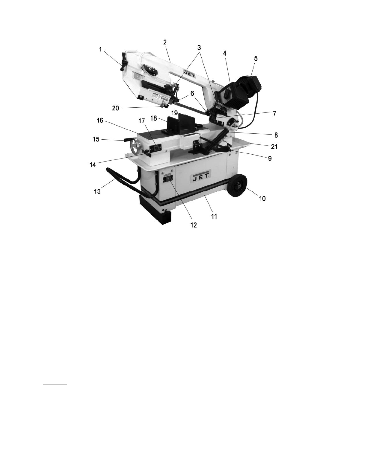
5.0 Features
Figure 1
1. Blade tension handle
2. Cast iron bow
3. Coolant taps
4. 3-speed gearbox
5. 1HP motor
6. Ball bearing bl ade g u ides
7. Chip brush
8. Hydraul ic cyl inder with regul ator valve
9. Adjustable work stop
10. Rubber tires
11. Steel st and with coolant t ank
12. Coolant toggle switch
13. Handle
14. Bow s top screw
15. Vise handwheel
16. Cast iron table
17. On/off toggle s witch
18. Floating vise jaw (adjustable)
19. Fixed vise jaw ( adjustable)
20. Shut-off tab
21. Drain pan
6.0 Specifications
Model Number .......................................................................................................................................... HBS-812G
Stock Number ................................................................................................................................................ 413460
Materials:
Frame .................................................................................................................................................... cast iron
Table ...................................................................................................................................................... cast iron
Band wheels ........................................................................................................................................... cast iron
Stand ........................................................................................................................................................... steel
Blade included ................................................................................................................... bi - metal, variable tooth
Blade guides ..................................................................................................................................... ball bear in g
Tires .......................................................................................................................................................... rubber
6
Page 7

Capacities:
Vise adjustment angle ........................................................................................................................ 0 to 45 deg.
Round capacity at 90° ........................................................................................................................8” (203 mm)
Round capacity at 45° ........................................................................................................................5” (127 mm)
Rectangle capacity at 90° (W x H) .............................................................................. 8” x 11-1/4” (203 x 286 mm)
Rectangle capacity at 45° (W x H) ...................................................................................... 5” x 8” (127 x 203 mm)
Gearbox capacity .......................................................................................................................... 0.3L (10.14 oz)
Coolant tank capacity ........................................................................................................................ 9L (2.25 gal)
Motor an d Electric al s:
Motor type (UL Listed) ................................................................................. totally enclosed fan cooled, induction
Horsepower .................................................................................................................................. 1 HP (0.75 kW)
Phase......................................................................................................................................................... sing le
Voltage ....................................................................................................................... 115/230 V (prewired 115V)
Cycle ........................................................................................................................................................... 60H z
Listed FLA (full l oad am ps) ......................................................................................................................... 10/5 A
Starting amps ................................................................................................................................................ 28 A
Running amps (no load) ................................................................................................................................ 6.2A
Power transfer ......................................................................................................................................... gearbox
Control switch ............................................................................................................................................. toggle
Motor speed .......................................................................................................................................... 1720 rpm
Blade speeds............................................................................................................................ 145, 200, 245 fpm
Power cord length ......................................................................................................................... 6 feet (180 cm)
Power cord type.................................................................................................................................. 16AWGx3c
Power plug installed ........................................................................................................................................ yes
Recommended circuit size
1
........................................................................................................................... 15 A
Noise emission:
without load......................................................................................................... 70 dB at 60 inches from blade
with load ............................................................................................................. 75 dB at 60 inches from blade
Coolant pump:
Horsepower ............................................................................................................................................... 1/8 HP
Phase......................................................................................................................................................... sing le
Voltage .................................................................................................................................................115/230 V
Cycle ........................................................................................................................................................... 60H z
Listed FLA (full l oad am ps) ....................................................................................................................0.5/0.25 A
Control switch ............................................................................................................................................. toggle
Weights:
Net Weight .................................................................................................................................. 308 lb (140 kg)
Shipping We ig ht ............................................................................................................... ............ 364 lb (165 kg)
Dimensions:
Blade .............................................................................................. 3/4"W x 0.032”T x 93”L (19 x 0.9 x 2360 mm)
Blade wheel diameter ................................................................................................................. 11-1/2” (292mm)
Vise jaw height ..................................................................................................................................4” (1 0 2 mm)
Vise jaw depth ............................................................................................................................. 8-1/2” (216 mm)
Table si ze (LxW) .............................................................................................................. 21” x 7” (533 x 178 mm)
Table height from floor .................................................................................................................. 24” (60 9.6 mm)
Tire diameter .....................................................................................................................................8” (203 mm)
Overall assembled, horizontal position............................................... 48”L x 22”W x 42”H (1219 x 559 x 1067 mm)
Overall assembled, vertical position................................................... 60”L x 22”W x 66”H (1524 x 559 x 1676 mm)
Other:
Blade tension range .................................................................................. 22000-25000 lb/in² (1550-1760 kg/cm²)
1
subject to local and national electrical codes.
The specifications in this manual were current at time of publication, but because of our policy of continuous
improvement, JET reserves the right to change specifications at any time and without prior notice, without incurring
obligations.
7
Page 8
7.0 Set-Up and Assembly
7.1 Unpacking and cleanup
Insp ect co nte nt s of sh ipp ing co nta ine r f or ship pi ng
damage. Report any damage to your distributor.
Remove all contents from carton, and compare to
the contents list in this manual. Report any part
shortages to your distributor. Do not discard carton
or packing material until machine is assembled and
running satisfactorily.
Exposed metal areas have a rust preventative
applied. Remove this with a soft rag a nd solvent or
degreaser. Do not use cellulose-based solvents
such as paint thinner or lacquer thinner; these will
damage painted and plastic surfaces.
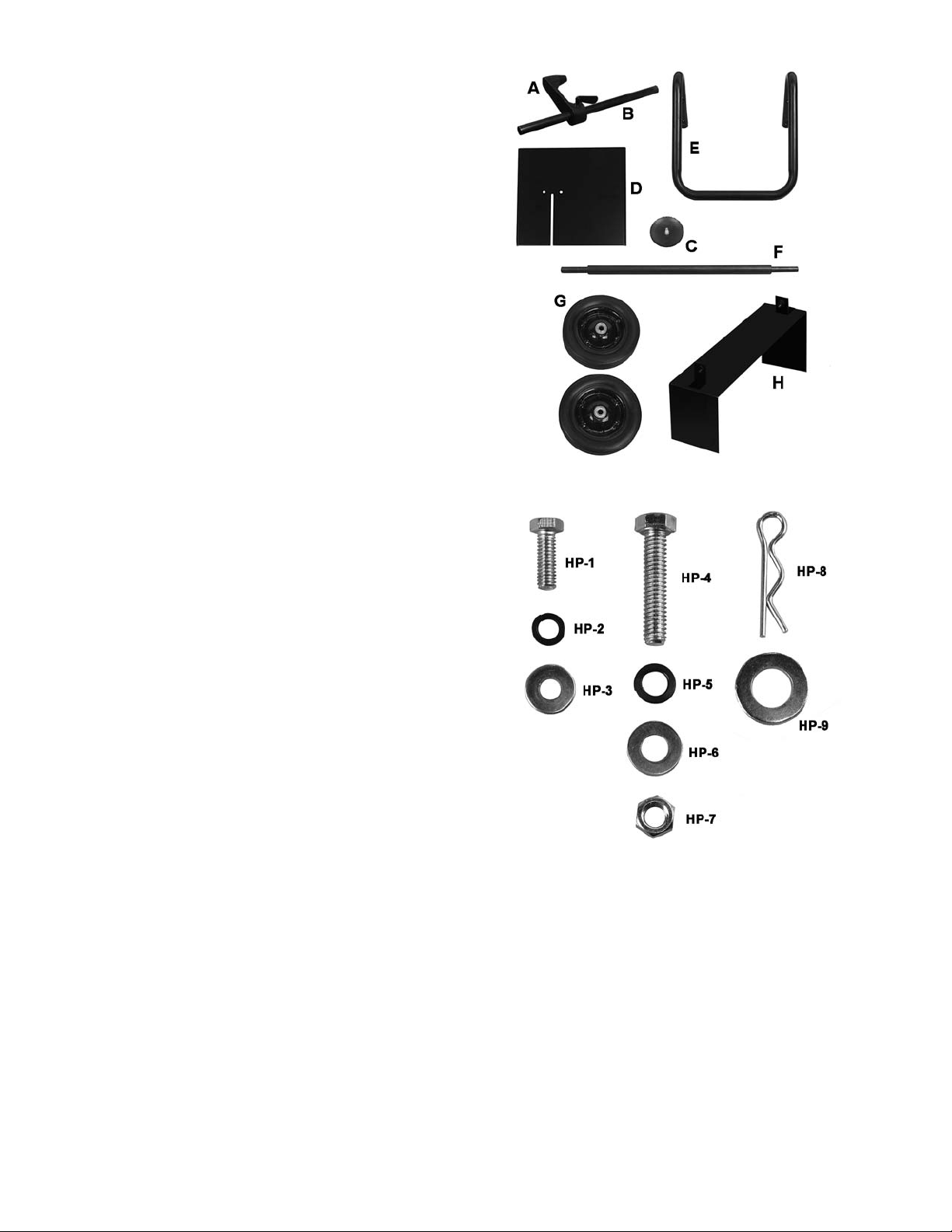
7.2 Shipping contents
If you do not see a part below, check the machine;
some parts may have come pre-assembled to t he
saw.
Refer to Figures 2 and 3.
1 Band Saw
1 Workstop – A
1 Workstop rod – B
1 Filter screen – C
1 Vertical cutting plate – D
1 Handle – E
1 Axle – F
2 Wheels – G
1 Foot stand – H
1 Instructions and Parts Manual (not shown)
1 Warranty Card (not shown)
Hardware Package (p/n HBS812G-HP):
Figure 2
2 Hex cap screws 1/4"x3/4" – HP-1
2 Lock washers 1/4" – HP-2
2 Flat washers 1/4" – HP-3
4 Hex cap screws 5/16"x1-1/2" – HP-4
4 Lock washers 5/16" – HP-5
4 Flat washers 5/16" – HP-6
4 Hex nuts 5/16" – HP-7
2 Cotter pins – HP-8
2 Flat washers 1/2" – HP-9
Tools required for assembly:
(2) 12mm wrenches
10mm wrench
Pliers
Figure 3
Hardware package HBS812G-HP
8
Page 9
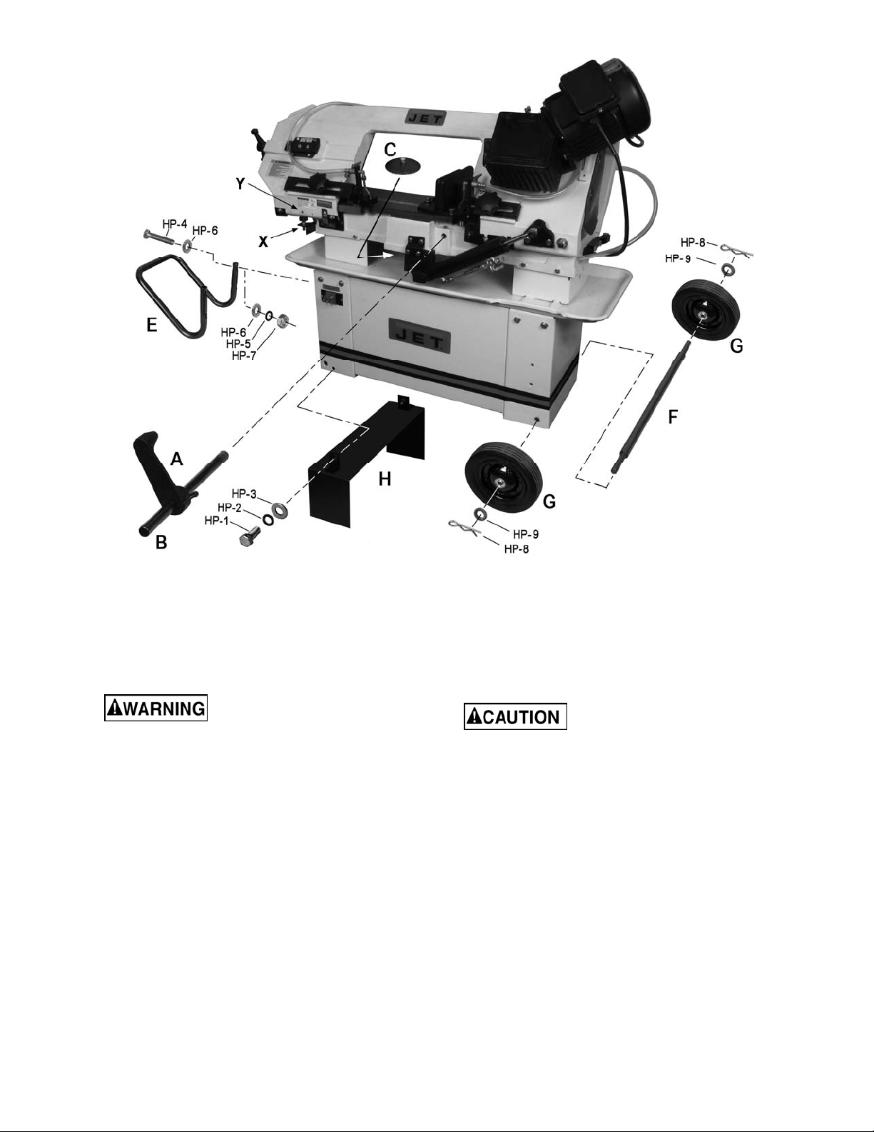
7.3 Assembly
Refer to Figure 4.
Figure 4
7. Remove stop bolt (X, Figure 4) and remove
shipping bracket (Y). Retain bracket in case
you must transport the machine in the future.
Reinstall stop bolt.
Band Saw should be
disconnected from electrical power during
assembly and setup.
1. Remove brackets holding saw to pallet.
2. Use properly rated lifting equipment (hoist or
forklift) with straps placed beneath cast iron
portion of saw.
3. Use blocking beneath saw, and install foot
stand (H). Secure with four screws and
washers (HP-1/2/3).
4. Install axle and wheels (F/G). Install cotter pin
(HP-8) through hole in axle, and bend back
legs of cotter pin to secure each wheel.
5. Slide workstop rod (B) into hole on saw base
and slide workstop (A) onto rod. (NOTE: Do
not insert rod too far so that it hits the vise
leadscrew).
6. Install handle (E), and place filter screen (C)
over coolant drain hole in pan.
After removal of shipping
bracket (Y), the stop bolt (X) must be reinstalled
and properly adjusted to prevent damage to the
on/off switch.
7.4 Vertical cutting plate
These steps are only necessary when using band
saw in vertical pos ition.
1. Disconnect machine from power source.
2. Raise bow to vertical position.
3. Remove two screws and remove seat plate, as
shown in Figure 5.
9
Page 10
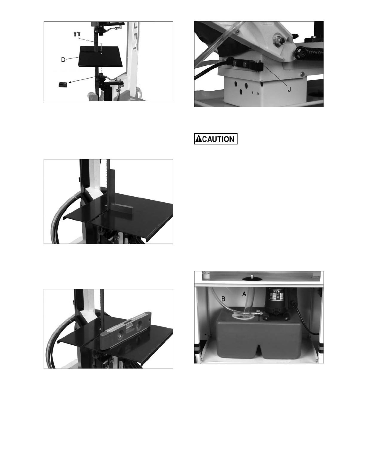
Figure 5
4. Guide blade through slot in vertical cutting
plate (D, Figure 5), and tighten with the two
screws.
5. Verify that vertical cutting plate is square to
blade, using a machinist’s square on the plate
and against the blade (Figure 6).
Figure 6
6. If adjustment is needed, loosen screws and
place shims where required. Tighten screws.
Figure 8
7.5 Coolant system
Make sure there is coolant in
the tank before operating, to prevent damage to
pump.
Use of a water-soluble coolant will increase cutting
efficiency and prolong blade life. Do not use black
cutting oil as a substitute.
1. Remove coolant return hose (A, Figure 9) from
filter cup, and slide tank out of saw base.
2. Fill tank to approximately 80% of capacity. Full
capacity is 9 liters (2.25 gal).
3. Place tank into base. Place coolant return
hose into the filter cup. Verify that opposite
end of coolant return hose is connected to the
coolant pan.
4. The coolant supply hose (B, Figure 9) should
connect to the taps on the blade guide
assemblie s.
7. Place a level on vertical cutting plate (Figure
7).
Figure 7
8. Turn stop screw (J, Figure 8) as needed, until
cutting plate is level. Tighten hex nut.
9. Close valve on c ylinder (lever perpendic ular to
cylinder) to secure bow in position.
Reinstall seat plate before using bow in horizontal
position.
Figure 9
10
Page 11

8.0 Electrical connections
2. Grounded, cord-connected tools intended for
use on a supply circuit having a nominal rating less
than 150 volts:
Electrical connections must
be made by a qualified electrician in
compliance with all relevant codes. This
machine must be properly grounded to help
prevent electrical shock and possible fatal
injury.
The HBS-812G Band Saw is rated at 115/230V
power, and pre-wired for 115 volt. The band saw
comes with a plug designed for use on a circuit
with a grounded outlet that looks like the one
pictured in A, Figure 10.
Before connecting to power source, be sure switch
is in off position.
It is recommended that the band saw be connected
to a dedicated 15 amp circuit with a 15 amp circ uit
breaker or time-delay fuse. Local codes take
precedence over recommendations.
8.1 Grounding instructions
1. All Grounded, Cord-connected Tools:
In the event of a malfunction or breakdown,
grounding provides a path of least resistance for
electric current to reduce t he risk of electr ic shock.
This tool is equipped with an electric cord having
an equipment-grounding conductor and a
grounding plug. The plug must be plugged into a
matching outlet that is properly installed and
grounded in accordance with all local codes and
ordinances.
Do not modify the plug provided - if it will not fit the
outlet, have the proper outlet installed by a
qualified electrician.
Improper connection of the equipment-grounding
conductor can result in a risk of electric shock. The
cond uctor with insulation having an o uter surface
that is green with or without yellow stripes is the
equipment-grounding conductor. If repair or
replacement of the electric cord or plug is
necessary, do not connect the equipmentgrounding conductor to a live terminal.
Check with a qualified
electrician or service personnel if the
grounding instructions are not completely
understood, or if in doubt as to whether the
tool is properly grounded. Failure to comply
may cause serious or fatal injury.
Use only 3-wire extension cords that have 3-prong
grounding plugs and 3-pole receptacles that accept
the tool's plug.
Repair or replace damaged or worn cord
immediately.
This tool is intended for use on a circuit that has an
outlet that looks like the one illustrated in A, Figure
10. An adapter, shown in B and C, may be used to
connect this plug to a 2-pole receptacle as shown
in B if a properly grounded outlet is not available.
The temporary adapter should be used only unt il a
properly grounded outlet can be installed by a
qualified electrician. This adapter is not permitted
in Canada. The green-colored rigid ear, lug, and
the like, extending from the adapter must be
connected to a permanent ground such as a
properly grounded outlet box.
3. Grounded, cord-connected tools intended for
use on a supply circuit having a nominal rating
between 150 - 250 volts, inclusive:
This tool is intended for use on a circuit that has an
outlet that looks like the one illustrated in D, Figure
10. The tool has a grounding plug that looks like
the plug illustrated in D. Make sure the tool is
connected to an outlet having the same
configuration as the plug. No adapter is available
or should be used with this tool. If the tool must be
reconnected for use on a diff erent type of electric
circuit, the reconnection should be made by
qualified service personnel; and after reconnection,
the tool should comply with all local codes and
ordinances.
Figure 10
8.2 Voltage conversion
1. To switch the incoming power leads for 230
volt operation, follow the wiring diagram on the
inside cover of motor junction box. Similar
diagrams are shown in Figures 11/12.
2. Change the wiring inside the junction box of
the coolant pump, according to the diagram
found there.
3. The plug on the end of the motor cord must be
replaced with a UL/CSA listed plug rated for
230V.
11
Page 12

9.0 Adjustments
The settings on your band saw, such as blade
squareness and tracking, were caref ully perf ormed
by the manufacturer. You should, however, verify
these before operating, in case misalignment has
occurred during shipping.
9.1 Squaring blade to table
Figure 11
Figure 12
8.3 Extension cords
The use of extension cords is discouraged; try to
position equipment near the power source. If an
extension cord becomes necessary, make sure the
cord rating is suitable for the amperage listed on
the machine’s motor plate. An undersized cord will
cause a drop in line voltage resulting in loss of
power and overheating.
Use Table 1 as a general guide in choosing the
correct size cord. If in doubt, use the next heavier
gauge. The smaller the gauge number, the heavier
the cord.
Ampere
Rating
More
Than
00 06 18 16 16 14
06 10 18 16 14 12
10 12 16 16 14 12
12 16 14 12
Not
More
Than
Extension Cord Recommendations
Volts
120
240
AWG
Total length of
cord in f eet
25
50
50
100
Table 1
100
200
Not
Recommended
150
300
1. Disconnect machine from power source.
2. Place machinist’s square (A, Figure 13) on
table and against blade.
3. Check to see that blade contacts the square
along entire width of blade.
4. If adjustment is needed, loosen screws (B,
Figure 13) and rotate blade guide assemblies
until blade makes contact with square along its
entire width.
5. Tighten screws (B).
NOTE: If adjustment of squaring blade to table was
necessary, re-verify all other blade adjustments.
Figure 13
9.2 Squaring blade to vise
1. Disconnect machine from power source.
2. Place a machinist’s square (A, Figure 14) on
the bed against the blade and the fixed vise
jaw. The square should lie along entire length
of jaw and blade without a gap.
3. If adjustment is necessary, loosen screws
holding vise (C, Figure 14) and shift vise until it
aligns with square.
4. Retighten screws.
12
Page 13

Figure 14
9.3 Vise positioning
9.3.1 90-degree cut
Keep hands away from blade
while adjusting vise. Do not make any
adjustments to vise while the machine is
running.
1. Make sure fixed jaw (D, Figure 15) has been
squared (section 9.2, Squaring blade to vise).
2. Position workpiece against fixed jaw.
3. Loosen screws (E) on floating jaw, and use
handwheel (F) to bring floating jaw into contact
with workpiece, allowing it to conform to the
shape.
4. Tighten screws (E).
5. Tighten clamping pressure with handwheel.
with workpiece, allowing it to conform to the
angle.
4. Tighten screws (E).
5. Tighten clamping pressure with handwheel.
9.3.3 Extended capacity
1. Remove two screws (C, Figure 16).
2. Reposition fixed vise in the secondary holes
(H).
3. Reinstall screws (C) and tighten.
Figure 16
9.4 Setting feed rate
The feed rate of the blade into the workpiece is
important to band saw performance. Excessive
pressure of blade against the workpiece may break
the blade or stall the saw. In contrast, insufficient
pressure rapidly dulls the blade.
The hydraulic cylinder resists movement of the bow
in the downward direction. It offers no resistance
when the bow is raised.
Figure 15
9.3.2 Miter c u t
1. Loosen screws on fixed jaw (C, Figure 16),
and floating jaw (E).
2. Swing both jaws to match desired angle on
scale (G). Tighten screws (C).
Note: The angle scale is sufficient for most
mitering operations. If greater precision is
needed, verify setting with a protractor.
3. Loosen screws (E) on floating jaw, and use
handwheel (F) to bring floating jaw into contact
To increase feed rate, turn dial (A, Figure 17)
counterclockwise. To decrease, turn clockwise.
To close hydraulic flow, turn lever (B) down,
perpendicular to cylinder, as shown in Figure 17.
To open hydraulic flow, turn lever (B) parallel to
cylinder.
Figure 17
Feed rate is adjusted by t he operator unt il the saw
is operating efficiently, usually determined by
13
Page 14

observing chip formation. See section 11.4,
Evaluating cutting efficiency.
9.5 Counterbalance spring
The counterbalance spring helps control the
amount of weight the saw bow puts on the
workpiece when the hydraulic control valve is fully
open. The hydraulic cylinder will not compensate
for improper counterbalance.
If the spring is not set properly, one can expect
poor performance, crooked cuts, tooth stripping,
stalling, and/or the blade running off the wheels.
Spring tension has been set by the manufacturer,
and should not require adjustment. If future
problems arise, indicating improper
counterbalance, adjust spring as follows:
1. Disconnect machine from power source.
2. Turn ON hydraulic cylinder valve and place
saw bow in horizontal position.
3. Turn feed rate valve on hydraulic cylinder
counterclockwise until it stops.
4. Place a weigh scale (such as a spring or
hanging scale) beneath blade tension handle,
and lift saw bow. Scale should indicate
approximately 5 to 6 kg (11-13 lb).
5. If adjustment is needed, loosen one nut and
tighten th e other (A, Figure 18) on the eye bolt,
until scale indicates 5 to 6 kg.
they straddle the work, severe damage to the
workpiece and to the blade can result.
To replace a blade:
1. Disconnect machine from power source.
2. Raise bow to vertical position, and secure in
place by turning off hydraulic cylinder.
3. Remove red blade guard by removing two
screws (A, Figure 19).
Red blade guard must be
reinstalled after new blade is fitted.
Figure 19
4. Remove brush assembly (B, Figure 19) by
removing two screws.
5. Loosen blade tension by turning handle (C,
Figure 20) counterclockwise.
Figure 18
9.6 Blade installation/replacement
This band saw is designed for
use with blades that are 3/4" wide by 0.032”
thick x 93” long. Use of blades with different
specification may cause inferior performance.
A general-use variable-tooth blade is provided with
this band saw.
The choice of blade pitch is governed by the
thickness of the work to be cut: the thinner the
workpiece, the more teeth advised. A minimum of
three teeth should engage the workpiece at all
times. If the teeth of the blade are so far apart that
Figure 20
6. Open back cover by loosening two lock knobs.
7. Carefully remove old blade. NOTE: Leather
gloves are recommended when handling saw
blades.
8. Install new blade first between bearing guides.
Make sure blade teeth face same direction as
shown on the blade direction label on saw. (If
teeth still point in wrong direction despite
mounting blade properly, the blade has been
turned inside-out. Twist blade right side-out
and reinstall.)
14
Page 15

9. Position blade around wheels, making sure it
rests near the flange on both wheels.
10. Tension blade using handle. Do not overtension. See section 9.7, Blade tension.
11. Close back cover and secure with knobs.
12. Install red blade guard, and brush assembly.
13. Connect machine to power source.
14. Run machine to verify that blade is tracking
properly. See section 9.8, Blade tracking.
9.7 Blade tension
Disconnect machine from
power source, and use caution when working
with sharp blade.
Blade tension is vital to achieving proper results
from the band saw. For shipping purposes, the
blade may not be at full tension – verify tension
before operating.
Proper blade tension is 1550 to 1760 kg/cm2
(22000-25000 lb/in2) as measured on a blade
tension gauge (not provided).
To set tension without the use of a tension gauge:
1. Disconnect machine from power source.
2. Install blade between wheels and between
bearings on blade guides.
3. Lightly tension blade to remove any sag by
turning handle (C, Figure 20) slightly
clockwise.
4. Turn tension handle (C, Figure 20) 1-3/4 to two
revolutions clockwise. This is equivalent to 800
kg (1764 lb) of blade tension.
Do not overtighten blade;
this may cause it to stretch or warp.
9.8 Blade tracking
Tracking the blade requires
that the band saw be operating while t he back
cover is removed. This adjustment should be
performed by qualified persons only.
Blade tracking has been tested at the factory.
Adjustment is rarely required when the blade is
used properly and if the blade is correctly welded.
If a tracking problem occurs, first inspect blade
condition, then adjust tracking as follows:
1. Raise bow to vertical position and secure by
turning off hydraulic cylinder valve.
2. The blade should be properly tensioned. Refer
to section 9.7 Blade tension.
3. Open back cover.
While performing the following
steps, keep the blade from rubbing excessively
on wheel flange. Excess rubbing will damage
wheel and/or blade.
4. Start saw and observe blade movement. Blade
should run next to, but not tightly against,
wheel flange.
5. If blade will not track in position, loosen
screws (E, Figure 21), but do not remove.
6. Turn set screw (F, Figure 21) counterclockwise so that blade starts to move away
from the flange; then immediately turn set
screw in the other direction so that blade
stops, then moves slowly back toward flange.
NOTE: This adjustment is sensitive; do it
gradually and in small increments allowing
blade to respond to the changes.
5. Close covers, connect to power source, and
run saw for 2 to 3 minutes to allow blade to
seat properly.
6. Disconnect machine from power source. Open
cover and loosen blade until it just begins to
sag.
7. Tighten blade until it straightens between
blade wheels and all sag is eliminated.
8. Tighten blade b y turning handle (C, Fig ure 20)
two full revolutions.
TIP: Slacken blade tension when finished with
operations, to prolong blade life. Make note of
indicator position on tension label (D, Figure 20) for
quickly returning tension to its previous setting.
Figure 21
15
Page 16

Keep fingers clear of blade
and wheel to avoid injury .
7. Turn set screw to stop shifting of blade on the
wheel as it gets closer to wheel flange. Put a
six-inch length of paper between blade and
wheel. The paper should not be cut as it
passes between wheel flange and blade.
8. Turn set screw a small amount. Repeat the
insertion of paper between wheel flange and
blade until paper is cut into two pieces.
NOTE: You may have to repeat the c heck with
the paper several times before the blade and
the flange cut the paper into two pieces. Do
not hurry the adjustment. Patience and
accuracy here will pay off with better, more
accurate, quieter cutting and longer machine
and blade life.
9. When the paper is cut, back off the set screw
slightly. This assures that the blade is not
touching the flange of the wheel.
10. Tighten two screws (E, Figure 21).
Figure 22
9.9 Test cutting to verify adjustment
Test cuts can be used to determine whether or not
you have adjusted the blade accurately. Use 2-inch
round bar stock to perform these test cuts, as
follows:
1. With bar stock securely clamped in the vise,
make a cut through the bar stock (see Figure
22.)
2. Mark the top of the bar stock.
3. Move the bar stock about 1/4-inch past the
blade so that you can begin a second cut.
4. Rotate the bar stock 180 degrees so the mark
you made is now at the bottom of the cut.
5. Make a cut through the bar stock.
6. Use a micrometer to measure the thickness
variation of the disk you have cut from the bar
stock. Measure at top and bottom of disk.
The saw blade can be considered correctly
adjusted when the variation measure is no more
than 0.012 inch across the face of the disk.
If you do not have a piece of 2-inch bar stock
available for a test cut, use a larger diameter test
piece rather than a smaller one. The maximum
thickness variation on any test piece should be no
more than 0.003 inch, per side, per inch of stock
diameter.
9.10 Blade speed
1. Turn machine OFF.
2. Turn lever (Figure 23) to desired setting –
1 = 145 feet per minute
2 = 200 feet per minute
3 = 245 feet per minute
Do not change blade speed
during cutting operation.
Material chips or shavings are the best indicator of
proper blade speed and downfeed rate. See
section 11.4, Evaluating cutting efficiency.
Figure 23
16
Page 17

9.11 Blade guide adjustment
1. Loosen knobs (A, Figure 24).
2. Slide guide assemblies as close to workpiece
as possible without interfering with cut. This
will prevent excessive blade exposure, and
deflection of blade during cutting.
3. Retighten knobs.
Figure 24
The guide bearings come pre-adjusted from the
factory, but should be inspected frequently and
adjustments made as needed.
For most efficient operation and maximum
accuracy, provide 0.001” clearance between the
blade and the guide bearings. The bearings will still
turn freely with this clearance. If the clearance is
incorrect, the blade may track off the drive wheel.
1. Disconnect machine from power source.
2. Raise bow to vertical and secure in place by
turning off hydraulic cylinder.
3. Loosen socket head cap screw (B, Figure 25)
and adjust guide assembly until back roller
bearing (C) is slightly contacting back edge of
blade.
Make sure power is
disconnected and hands are protected
before handling blade.
6. Tighten nut (D).
7. Repeat for other blade guide assembly.
Figure 26
9.12 Chip brush
The chip brush (B, Figure 19) must be properly
adjusted and maintained in working condition;
otherwise damage to blade can occur. Adj ust the
brush so that its bristles overlap the blade.
Replace brush if it becomes worn or damaged.
9.13 On/off switch
The stop scr ew (A, Figure 27)
must be properly adjusted to prevent damage
to the on/off switch.
Make sure the stop screw (A, Figure 27) is properly
adjusted in conjunction with the shut-off tab (B,
Figure 27). Too much pressure from the shut-off
tab can damage the on/off switch.
Figure 25
4. Loosen nut (D) and rotate eccentric shaft (E)
to adjust side bearing until bearing just
touches side of blade. Do not pinch the blade.
5. Blade should still move up and down freely
when grasped as in Figure 26. Make sure
blade teeth do not interfere with guide
bearings.
Figure 27
17
Page 18

10.0 Operating controls
To start saw, toggle switch (C, Figure 27) to ON.
To stop saw before it reaches the end of cut, toggle
switch (C) to OFF. Otherwise, saw will
automatically stop at the end of a cut.
Toggle the coolant switch (D, Figure 28) to ON.
Flow of coolant to blade area is controlled by the
taps connected to the blade guide assemblies.
Figure 28
IMPORTANT: When cutting magnesium, never
use soluble oils or emulsions (oil-water mix) as
water will greatly intensify any accidental
magnesium chip fire. See your industrial coolant
supplier for specific coolant recommendations
when cutting magnesium.
11.0 Operation
11.1 Pre-Operation inspection
Give machine an overall inspection and verify the
following:
1. Guards and covers are in place and in working
order.
2. Blade tooth direction matches diagram on
bow.
3. Blade is properly tensioned, and tracking
correctly on wheels.
following procedure will be adequate for break-in of
JET-supplied blades on lower alloy ferrous
materials.
1. Clamp a round section workpiece in the vise.
The workpiece should be 2 inc hes or larger in
diameter.
2. Set the saw on low speed. Start the c ut with a
very light feed rate.
3. When the saw has completed 1/3 of the cut,
increase the feed rate slightly and allow the
saw to complete the cut.
4. Keep the same hydraulic cylinder setting and
begin a second cut on the same or similar
workpiece.
5. When the blade has completed about 1/3 of
the cut, increase feed rate. Watch the chip
formation until cutting is at its most efficient
rate and allow the saw to complete the cut
(see section 11.4, Evaluating cutting
efficiency).
6. The blade is now ready for regular service.
11.3 General operating procedure
1. Raise bow until it will clear workpiece by a few
inches, and close hydraulic cylinder valve to
secure it in place.
NOTE: Never start a cut with blade
contacting workpiece.
2. Place workpiece in vise and tighten vise. The
workpiece should be fitted directly between the
jaws without adding other objects.
When workpiece to be cut is a profiled section,
flat piece or special shape, refer to examples
in Figure 29 for proper clamping positions. The
top row shows acceptable clamping positio ns;
the bottom row shows unacceptable positions.
If thickness of profiled section is very thin, a
piece which duplicates the profile should be
fitted inside the workpiece itself, to prevent
workpiece being crushed between the jaws.
4. Side and rear blade guide bearings are
properly adjusted.
5. Coolant level is sufficient.
6. Gearbox is properly lubricated.
7. Do not begin cut on a sharp edge; file edge
first.
11.2 Blade break-in procedure
New blades are very sharp and, therefore, have a
tooth geometry which is easily damaged if a careful
break-in procedure is not followed. Consult the
blade manufacturer’s literature for break-in of
specific blades on specific materials. However, the
Figure 29
Never hold a workpiece by
hand when cutting it – t he workpiece s hould be
firmly secured in the vise. Do not reach into the
cutting area during cutting operations.
18
Page 19

3. Position work stop if needed.
4. Position blade guides as close to workpiece as
possible.
5. Move speed setting lever to desired position.
Do not move speed setting lever during a
cutting operation.
6. Set a suitable feed rate for that operation on
the hydraulic cylinder dial.
7. Toggle ON switch to begin blade rotation.
Allow blade to reach full speed before
beginning cut.
8. Turn on coolant flow. Adjust flow valves as
needed.
9. Open valve on hydraulic cy linder to allow bow
to descend in a gradual and controlled
ma nne r .
10. The machine will shut off at the completion of
the cut. Turn off coolant flow and remove
workpiece.
11. Return bow to raised position for next cut.
11.4 Evaluating cutting efficiency
Is the blade cutting efficiently? The best way to
determine this is to observe the chips formed by
the cut.
If chip formation is powdery, then t he feed rate is
much too light, or the blade is dull.
If chips are curled, but colored — that is, either
blue or straw-colored from heat generated during
the cut — then the feed rate is too high.
If chips are slightly curled and are not colored by
heat, the blade is sufficiently sharp and is cutting at
its most efficient rate.
Check guide bearings frequently to make sure t hat
they are properly adjusted and turning freely.
Grease the vise lead screw (Figure 30) as needed,
with a general purpose grease.
Figure 30
If the power cord is worn, c ut, or damaged in any
way, have it replaced immediately.
Ball bearings on blade guide assemblies and blade
wheels are permanently lubricated and sealed.
They require no further lubrication.
Place a thin coat of oil on the table surface on
which the vise jaw slides.
12.1 Coolant level
Maintain coolant level. Low coolant level can cause
foaming and high blade temperatures. Replace
dirty coolant; dirty or weak coolant can clog the
pump, cause crooked cuts, a low cutting rate
and/or permanent blade damage. To fill the tank,
remove the filter cup and pour coolant into the hole
to about 80% of full capacity. Full capacity is 9
liters (2.5 gal). Follow coolant manufacturer’s
instructions for proper use and disposal.
12.0 Maintenance
Before doing maintenance on
the machine, disconnect it from the electrical
supply by pulling out the plug or switching off
the main switch! Failure to comply m ay cause
serious inju ry.
Keep all surfaces clean and free of rust, slag,
chips , and coolant build-up.
Clear metal particles with a small paint brush or
parts cleaning brush.
Clean filter screen.
Do not use compressed air, as it may force chips
into the guide bearings and ot her critical areas of
the saw.
Wipe saw down with a clean, dry cloth, and oi l all
unpainted surfaces with light machine oil.
Keep blade guides clean and free of metal
particles.
12.2 Gear box
To change gear box oil:
1. Disconnect machine from power source.
2. Place bow in vertical position.
3. Remove drain plug (A, Figure 31) and drain oil.
(Follow local regulations for disposal of used
oil.)
4. Reinstall drain plug and return bow to
horizontal position.
5. Remove vent plug (B), and fill gear box
through the hole with approximately 0.3L
(10.14 oz.) of 90W oil.
6. Rein st all vent plug ( B ) .
Completely drain and refill gear box after the first
90 days of operation. Thereafter, change every six
months.
19
Page 20

Periodically, after draining remove screws, cover
and gasket, and wipe out residual oil from gearbox
interior with a rag, before refilling. Also do this if
ch anging oil brands.
Figure 31
13.0 Troubleshooting the HBS-812G
Trouble Probable Cause Remedy
Motor will not start. No incoming po wer. Check plug connect ion.
Blown electrical panel fuses or tripped
ci r cuit breaker s.
Defective motor, switch, power cable, or
plug.
Band Saw vibrates
excessively.
Miter cuts not accurate.
Cuts not square. Feed rate too fast. Decrease feed rate.
Base on uneven surface. Adjust base for even support.
Saw blade has cracks. Replace blade immediately.
Too heavy a cut. Reduce feed rate and blade speed.
Mat eri al not clamped p roperly, or v i se
screws not tightened.
Blade is worn, cutting crooked. Replace blade.
Incorrect blade toothing in relation to
workpiece.
Blade is worn, cutting crooked. Replace blade.
Incorrect adjustment of bearing guides
and guide assembly.
Workpiece incorrectly positioned in vise.
Replace fuses, or reset breakers.
Qualified electrician/service personnel
should inspect these items.
Tighten vise screws securely. Use an
adjustable square or protractor to verify
angle settings.
Check Machinery’s Handbook for
recommended blade type.
Readjust guide assemblies.
Check positioning and clamping in the
vise.
Finished s urface of
workpiece is rough,
unsatisfactory.
Poor blade tension. Check and correct if neede d.
Blade is dull. Replace blade.
Improper blade for cutting operation.
Feed rate too fast. Reduce feed rate.
Check Machinery’s Handbook for blade
recommendations.
20
Page 21

Trouble Probable Cause Remedy
Excessive blade
breakage.
Unusual wear on
side/back of blade,
Premature blade
dulling.
Blade tension too low.
Incorrect blade tension. Adjust blade tension.
Incorrect blade speed or feed rate. Adjust accordingly.
Workpiece loos e in vi se. Clamp workpiece secu rely.
Blade rubs on wheel flange. Adjust blade tracking.
Teeth too coarse for material. Use appropriate blade for material.
Teeth in contact w ith w orkp iece before
saw is started.
Blade guides are misaligned. Adjust blade guides as needed.
Blade too thick for wheel diameter. Use thinner blade.
Cracking at weld; poor annealing of blade. Replace blade.
Blade guides worn. Replace guides.
Blade guide bearings not adjusted. Adjust blade guide bearings.
Blade guide bearing bracket is loose. Tighten blade guide bearing bracket
Teeth too coarse. Use finer tooth blade.
Blade speed too fast. Reduce speed.
Inadequate feed rate. Adjust cylinder dial setting as needed.
Hard spots or scale on material.
Increase blade tension.
Start motor before blade contacts
workpiece.
Hard Spots: Increase feed rate. Scale:
Reduce speed and increase feed rate.
No coolant flow.
Work hardening of mat eri al (es pecially
stainless steel)
Blade installed backwards.
Insufficient blade tension. Adjust as needed.
Pump motor burned out. Replace pump.
Filter screen c logged. Cl ean fi lt er screen.
Coolant level low. Add coolant to tank.
Increase feed rate.
Remove blade, twist inside-out and re-
install.
14.0 Replacement Parts
Replacement parts are listed on the followi ng pages. To order parts or reach our service departm ent, call 1800-274-6848, Monday through Friday (see our website for business hours, www.jettools.com). Having the
Model Number and Serial Number of your machine available when you call will allow us to serve you quickly
and accurately.
21
Page 22

14.1.1 HBS-812G Table and Stand Assembly – Exploded View
22
Page 23

14.1.2 HBS-812G Bow Assembly – Exploded View
23
Page 24

14.1.3 HBS-812G Table, Bow, Stand Assemblies – Parts List
Index No. Part No . Description Size Qty
1 ................ HBS812G-1 ............... Bottom Pan .............................................................. ...................................... 1
2 ................ HBS812G-2 ............... Leg (Left) ................................................................. ...................................... 1
2-1 ............. HBS812G -2-1........... Foot Stand ............................................................... ...................................... 1
2-2 ............. TS-0680021 .............. Flat Washer ............................................................. 1/4" ................................ 2
2-3 ............. TS-0720071 .............. Spring Washer ......................................................... 1/4" ................................ 2
2-4 ............. TS-0050031 .............. Hex Cap Screw ........................................................ 1/4" x 3/4"...................... 2
2-5 ............. HVBS710S-13 ........... Handl e ..................................................................... ...................................... 1
2-6 ............. TS-0051071 .............. Hex Cap Screw ........................................................ 5/16" x 1-1/2" ................ 4
2-7 ............. TS-0680041 .............. Flat Washer ............................................................. 5/16" .............................. 4
2-8 ............. TS-0680041 .............. Flat Washer ............................................................. 5/16" .............................. 4
2-9 ............. TS-0720081 .............. Spring Washer ......................................................... 5/16" .............................. 4
2-10 ........... TS-0561021 .............. Hex Nut .................................................................... 5/16" .............................. 4
3 ................ HBS812G-3 ............... Leg (Right) ............................................................... ...................................... 1
4 ................ HBS812G-4 ............... Front Panel .............................................................. ...................................... 1
5 ................ HBS812G-5 ............... Shelf......................................................................... ...................................... 1
10 .............. HBS812G-10 ............. Switch Bracket ......................................................... ...................................... 1
11 .............. HBS812G-11 ............. Toggle Switch .......................................................... ...................................... 1
12 .............. HBS812G-12 ............. Switch Box ............................................................... ...................................... 1
13 .............. TS-0081031 .............. Hex Cap Screw ........................................................ 5/16" x 3/4".................... 8
14 .............. TS-0680041 .............. Flat Washer ............................................................. 5/16" .............................. 8
15 .............. TS-0680041 .............. Flat Washer ............................................................. 5/16" .............................. 8
16 .............. TS-0720081 .............. Spring Washer ......................................................... 5/16" .............................. 8
17 .............. TS-0561021 .............. Hex Nut .................................................................... 5/16" .............................. 8
18 .............. TS-0051011 .............. Hex Cap Screw ........................................................ 5/16" x 1/2".................... 6
19 .............. TS-0561021 .............. Hex Nut .................................................................... 5/16" .............................. 6
20 .............. HBS812G-20 ............. Hydraulic Cylinder.................................................... ...................................... 1
21 .............. TS-1505061 .............. Socket Head Cap Screw.......................................... M10 x 40 ....................... 1
22 .............. TS-0680041 .............. Flat Washer ............................................................. 3/8" ................................ 1
24 .............. TS-1540071 .............. Hex Nut .................................................................... M10 ............................... 1
25 .............. TS-0051051 .............. Hex Cap Screw ........................................................ 5/16" x 1"....................... 2
26 .............. TS-0720081 .............. Spring Washer ......................................................... 5/16" .............................. 2
27 .............. HBS812G-27 ............. Support Pin .............................................................. ...................................... 1
28 .............. TS-0267041 .............. Socket Set Screw .................................................... 1/4" x 3/8"...................... 1
29 .............. HBS812G-29 ............. Bottom Support ........................................................ ...................................... 1
30 .............. HBS812G-30 ............. Holding Plate ........................................................... ...................................... 1
31 .............. TS-0720081 .............. Spring Washer ......................................................... 5/16" .............................. 2
32 .............. TS-0051021 .............. Hex Cap Screw ........................................................ 5/16" x 5/8".................... 2
33 .............. TS-0680061 .............. Flat Washer ............................................................. 1/2" ................................ 2
34 .............. HVBS710S-16 ........... Wheel....................................................................... 8" ................................... 2
35-1 ........... HVBS710S-18 ........... Axle .......................................................................... ...................................... 1
36 .............. HVBS710S-19 ........... Cotter Pin ................................................................. ...................................... 2
37 .............. HBS812G-37 ............. Toggle Switch .......................................................... ...................................... 1
38 .............. HBS812G-38 ............. Electric Cord Assembly............................................ ...................................... 1
39 .............. HBS812G-39 ............. Table ........................................................................ ...................................... 1
40 .............. TS-0051051 .............. Hex Cap Screw ........................................................ 5/16" x 1"....................... 5
41 .............. TS-0680041 .............. Flat Washer ............................................................. 5/16" .............................. 5
42 .............. TS-0720081 .............. Spring Washer ......................................................... 5/16" .............................. 5
43 .............. TS-0561021 .............. Hex Nut .................................................................... 5/16" .............................. 5
44 .............. HVBS710S-26 ........... Filter ......................................................................... ...................................... 1
45 .............. HVBS710SG-204 ...... Round Hd. Screw..................................................... 3/16" x 3/8".................... 2
46 .............. HBS812G-46 ............. Switch Box Asse mbl y .............................................. ...................................... 1
47 .............. HVBS710S-82 ........... Handwheel ............................................................... ...................................... 1
48 .............. TS-0270031 .............. Socket Set Screw .................................................... 5/16" x 3/8".................... 1
49 .............. HVBS710S-85 ........... Key........................................................................... 5 x 20mm ...................... 1
50 .............. HVBS710S-84 ........... Lead Screw .............................................................. .......... ............................ 1
51 .............. HBS812G-51 ............. Nut Seat ................................................................... ...................................... 1
57 .............. TS-0051021 .............. Hex Cap Screw ........................................................ 5/16" x 5/8".................... 2
58 .............. TS-0720081 .............. Spring Washer ......................................................... 5/16" .............................. 2
58-1 ........... TS-0680041 .............. Flat Washer ............................................................. 5/16" .............................. 2
24
Page 25

Index No. Part No . Description Size Qty
59 .............. HBS812G-59 ............. Support Bracket ....................................................... ...................................... 1
60 .............. HBS812G-60 ............. Stop Screw .............................................................. ...................................... 1
61 .............. TS-0561021 .............. Hex Nut .................................................................... 5/16" .............................. 2
62 .............. TS-0060051 .............. Hex Cap Screw ........................................................ 3/8" x 1"......................... 1
64 .............. HBS812G-64 ............. 90° Position Support ................................................ ...................................... 1
65 .............. TS-0561031 .............. Hex Nut .................................................................... 3/8" ................................ 2
66 .............. TS-0720091 .............. Spring Washer ......................................................... 3/8" ................................ 2
70 .............. TS-0060071 .............. Hex Cap Screw ........................................................ 3/8" x 1-1/2" .................. 2
71 .............. TS-0081031 .............. Hex Cap Screw ........................................................ 5/16" x 3/4".................... 1
72 .............. HVBS710S-107 ......... Thumb Screw........................................................... ...................................... 1
73 .............. HBS812G-73 ............. Work Stop ................................................................ ...................................... 1
74 .............. HBS812G-74 ............. Work Stop Rod ........................................................ ...................................... 1
75 .............. TS-0640112 .............. Nylon Hex Nut.......................................................... 1/2" ................................ 2
76 .............. TS-0680061 .............. Flat Washer ............................................................. 1/2" ................................ 2
77 .............. HVBS710S-182 ......... Bearing Bushing ...................................................... ...................................... 1
80 .............. HVBS710S-62 ........... Pivot Shaft ............................................................... 22mm ............................ 1
80-1 ........... HVBS710S-61 ........... Bushing .................................................................... Ø22 x 28 x 7mm............ 1
81 .............. HBS812G-81 ............. Pivot Arm ................................................................. ...................................... 1
85 .............. TS-0720091 .............. Spring Washer ......................................................... 3/8" ................................ 2
85-1 ........... TS-0680041 .............. Flat Washer ............................................................. 3/8" ................................ 2
86 .............. TS-0060071 .............. Hex Cap Screw ........................................................ 3/8" x 1-1/2" .................. 2
87 .............. HVBS710S-126 ......... Spring ...................................................................... ...................................... 1
88 .............. HVBS710S-125 ......... Spring Adjusting Rod ............................................... 3/8" ................................ 1
89 .............. HVBS710S-124 ......... Spring Bracket ......................................................... ...................................... 1
90 .............. TS-0051051 .............. Hex Cap Screw ........................................................ 5/16" x 1"....................... 1
91 .............. TS-0561031 .............. Hex Nut .................................................................... 3/8" ................................ 2
92 .............. TS-0720081 .............. Spring Washer ......................................................... 5/16" .............................. 1
92-1 ........... TS-0680041 .............. Flat Washer ............................................................. 5/16" .............................. 1
93 .............. TS-0561021 .............. Hex Nut .................................................................... 5/16" .............................. 1
94 .............. HBS812G-94 ............. Floating Vise Jaw..................................................... ...................................... 1
95 .............. HBS812G-95 ............. Fixed Vise Jaw......................................................... ...................................... 1
96 .............. HVBS710S-119 ......... Hexagonal Stud ....................................................... ...................................... 1
96-1 ........... TS-0720091 .............. Spring Washer ......................................................... 3/8" ................................ 2
96-2 ........... TS-0680041 .............. Flat Washer ............................................................. 3/8" ................................ 1
97 .............. TS-0060071 .............. Hex Cap Screw ........................................................ 3/8" x 1-1/2" .................. 1
98 .............. TS-0070031 .............. Hex Cap Screw ........................................................ 1/2" x 1-1/2" .................. 1
98-1 ........... TS-0720111 .............. Spring Washer ......................................................... 1/2" ................................ 2
98-2 ........... TS-0680061 .............. Flat Washer ............................................................. 1/2" ................................ 1
99 .............. TS-0100041 .............. Hex Cap Screw ........................................................ 1/2" x 1-1/4" .................. 1
100 ............ HBS812G-100 ........... Scale ........................................................................ ...................................... 1
101 ............ TS-0209080 .............. Socket Head Cap Screw.......................................... 3/8" x 1-3/4" .................. 1
101-1 ......... TS-0561032 .............. Hex Nut .................................................................... 3/8" ................................ 1
102 ............ HVBS710S-5 ............. Clear Hose ............................................................... 1" ................................... 1
103 ............ HVBS710S-6 ............. Pump ....................................................................... 1/8HP 1PH .................... 1
104 ............ TS-0050011 .............. Hex Cap Screw ........................................................ 1/4" x 1/2"...................... 4
107 ............ HVBS710S-12 ........... Coolant Tank ........................................................... 9L .................................. 1
107-1 ......... HVBS7M W-66-1N ..... Plastic Funnel .......................................................... ...................................... 1
108 ............ HVBS710S-9 ............. Hose Fitting.............................................................. ...................................... 1
109 ............ HVBS710S-10 ........... Hose Clamp ............................................................. 13 mm ........................... 1
110 ............ HVBS710S-11 ........... Hose ........................................................................ 5/16" .............................. 1
111 ............ HBS812G-111 ........... Bow .......................................................................... ...................................... 1
117 ............ HVBS710SG-130 ...... Key........................................................................... 6 x 6 x 20mm ................ 1
119 ............ TS-0060051 .............. Hex Cap Screw ........................................................ 3/8" x 1"......................... 1
119-1 ......... TS-0720091 .............. Spring Washer ......................................................... 3/8" ................................ 1
119-2 ......... TS-0680041 .............. Fl at Washer ............................................................. 3/8" ................................ 1
121-1 ......... HVBS710SG-196-1 ... Gear Box Assembly (serial No. 150400349 and lower)..................................... 1
121-1 ......... HVBS710SG-196-1N Gear Box Assembly (serial No. 150600350 and higher) ................................... 1
122 ............ TS-0720081 .............. Spring Washer ......................................................... 5/16" .............................. 4
123 ............ TS-0051061 .............. Hex Cap Screw ........................................................ 5/16" x 1-1/4" ................ 4
123-1 ......... TS-0267041 .............. Socket Set Screw .................................................... 1/4" x 3/8"...................... 2
124 ............ HVBS710S-133 ......... Drive Wheel ............................................................. ...................................... 1
125 ............ TS-1503051 .............. Socket Head Cap Screw (serial No. 150400349 and lower) 6 x 20mm ............ 5
25
Page 26

Index No. Part No . Description Size Qty
126 ............ HVBS710SG-129 ...... Vent Plug ................................................................. ...................................... 1
127 ............ .................................. Blade (local purchase) ............................................. 3/4" x 0.032" x 93" ........ 1
128 ............ HBS812G-128 ........... Blade Back Cover .................................................... ...................................... 1
129 ............ HVBS710S-136 ......... Wheel Cover ............................................................ ...................................... 1
130 ............ HVBS710S-137 ......... Knob ........................................................................ 1/4" ................................ 2
130-1 ......... TS-0680021 .............. Fl at Washer ............................................................. 1/4" ................................ 2
131 ............ HVBS710S-140 ......... Adjustable Guide Knob ............................................ 3/8" ................................ 2
132 ............ HVBS710S-141 ......... Adjustable Bracket (Rear)........................................ ...................................... 1
133 ............ BB-608ZZ .................. Ball Bearing ............................................................. 608ZZ............................ 2
134 ............ HVBS710S-144 ......... Adjustable Blade Seat (Rear) .................................. ...................................... 1
135 ............ HVBS710S-143 ......... Bearing Pin .............................................................. 8mm .............................. 2
136 ............ HVBS710S-146 ......... Eccentric Shaft Assembly ........................................ ...................................... 2
136-1 ......... HVBS710S-146-1...... Center Shaft Assembly ............................................ ...................................... 2
137 ............ TS-0561032 .............. Hex Nut .................................................................... 3/8" x 24UNF ................ 4
137-1 ......... TS-0720091 .............. Spring Washer ......................................................... 3/8" ................................ 4
141 ............ TS-081F031 .............. Flat Head Screw ...................................................... 1/4" x 1/2"...................... 2
142 ............ HVBS710S-147-1...... Seat Plate ................................................................ ...................................... 1
143 ............ HVBS710S-144-1...... Adjustable Blade Seat (Front).................................. ...................................... 1
144 ............ TS-0060061 .............. Hex Cap Screw ........................................................ 3/8" x 1-1/4" .................. 2
145 ............ HBS812G-145 ........... Top Support ............................................................. ...................................... 1
146 ............ TS-0720091 .............. Spring Washer ......................................................... 3/8" ................................ 2
147 ............ TS-0561032 .............. Hex Nut .................................................................... 3/8" ................................ 2
148 ............ HVBS710S-139 ......... Round Hd. Screw..................................................... 1/4" x 1/2"...................... 2
149 ............ TS-0680021 .............. Flat Washer ............................................................. 1/4" ................................ 2
150 ............ HVBS710S-158 ......... Brush Holder ............................................................ ...................................... 1
153 ............ HVBS710S-161 ......... Brush ....................................................................... ...................................... 1
156 ............ HVBS710S-163 ......... Nozzle Cock............................................................. ...................................... 2
157 ............ TS-0267041 .............. Socket Set Screw .................................................... 1/4" x 3/8"...................... 2
158 ............ HVBS710S-164 ......... Nozzle Cock Support ............................................... ...................................... 2
159 ............ HVBS710S-170 ......... Valve ........................................................................ ....... ............................... 2
160 ............ TS-0267021 .............. Socket Set Screw .................................................... 1/4" x 1/4"...................... 1
160-1 ......... HVBS710S-160 ......... Fixed Bushing .......................................................... ...................................... 1
161 ............ HVBS710S-166 ......... Hex Cap Screw ........................................................ 5/16" x 1-1/8" ................ 2
161-1 ......... TS-0720081 .............. Spring Washer ......................................................... 5/16" .............................. 2
163 ............ HVBS710S-173 ......... Adjustable Bracket (Front) ....................................... ...................................... 1
164 ............ HVBS710S-174 ......... Blade Guard............................................................. ...................................... 1
164-1 ......... HVBS710S-175 ......... Round Hd. Screw..................................................... 3/16” x 1/4" .................... 2
165 ............ TS-0050011 .............. Hex Cap Screw ........................................................ 1/4" x 1/2"...................... 4
166 ............ HVBS710S-176 ......... Sliding Guide Plate .................................................. ...................................... 2
167 ............ TS-0270071 .............. Socket Set Screw .................................................... 5/16" x 3/4".................... 1
168 ............ TS-0051071 .............. Hex Cap Screw ........................................................ 5/16" x 1-1/2" ................ 2
169 ............ HVBS710S-178 ......... Blade Tension Sliding Block .................................... ...................................... 1
170 ............ TS-0050011 .............. Hex Cap Screw ........................................................ 1/4" x 1/2"...................... 1
170-1 ......... TS-0720071 .............. Spring Washer ......................................................... 1/4" ................................ 1
170-2 ......... TS-0680021 .............. Fl at Washer ............................................................. 1/4" ................................ 1
171 ............ HVBS710S-181 ......... Sliding Draw Block ................................................... ...................................... 1
172 ............ HBS812G-172 ........... Shipping Bracket...................................................... ...................................... 1
174 ............ BB-6203ZZ ................ Ball Bearing ............................................................. 6203ZZ.......................... 2
175 ............ HVBS710S-184 ......... Idler Wheel............................................................... ...................................... 1
176 ............ TS-0680041 .............. Flat Washer ............................................................. 5/16" .............................. 1
176-1 ......... TS-0720081 .............. Spring Washer ......................................................... 5/16" .............................. 1
177 ............ TS-0081031 .............. Hex Cap Screw ........................................................ 5/16" x 3/4".................... 1
178 ............ HVBS710S-139 ......... Round Hd. Screw..................................................... 1/4" x 1/2"...................... 2
179 ............ TS-0680021 .............. Flat Washer ............................................................. 1/4" ................................ 2
180 ............ TS-0680041 .............. Flat Washer ............................................................. 3/8" ................................ 1
181 ............ HVBS710S-188 ......... Blade Tension Handle ............................................. ...................................... 1
182 ............ HVBS710S-147 ......... Vertical Cutting Plate ............................................... ...................................... 1
192-1 ......... HVBS710SG-192-1 ... Motor........................................................................ 1HP 1PH ....................... 1
………….HVBS710SG-192-MF ... Motor Fan (not shown)............................................. ...................................... 1
………….HVBS710SG-192-MFC . Motor Fan Cover (not shown) .................................. ...................................... 1
………….HVBS710SG-192-JB .... Juncti on Box ............................................................ ...................................... 1
………….HVBS710SG-192-JBC .. Junction Box Cover.................................................. ...................................... 1
26
Page 27

Index No. Part No . Description Size Qty
192-2 ......... HVBS710SG-192-2 ... Strain Relief ............................................................. ...................................... 1
193 ............ HVBS710S-193 ......... Key........................................................................... 5 x 5 x 20 mm ............... 1
194 ............ HVBS710SG-328 ...... Worm Shaft .............................................................. ...................................... 1
195 ............ TS-1503051 .............. Socket Head Cap Screw.......................................... 6 x 20mm ...................... 1
196 ............ HVBS710SG-195-1 ... Gear Flange ............................................................. ...................................... 1
197 ............ TS-1490031 .............. Hex Cap Screw ........................................................ 8 x 20mm ...................... 2
198 ............ TS-1550061 .............. Spring Washer ......................................................... 8mm .............................. 2
204 ............ TS-0050011 .............. Hex Cap Screw ........................................................ 1/4" x 1/2"...................... 2
205 ............ TS-0680021 .............. Flat Washer ............................................................. 1/4" ................................ 2
206 ............ HVBS710S-189 ......... Support Plate ........................................................... ...................................... 1
218 ............ HBS812G-218 ........... Shut-off Tab ............................................................. ...................................... 1
219 ............ TS-0680021 .............. Flat Washer ............................................................. 1/4" ................................ 1
220 ............ TS-0720071 .............. Spring Washer ......................................................... 1/4" ................................ 1
221 ............ TS-0050011 .............. Hex Cap Screw ........................................................ 1/4" x 1/2"...................... 1
222 ............ HVBS710S-171 ......... Hose Clamp ............................................................. ...................................... 5
223 ............ HVBS710S-169 ......... Hose ........................................................................ ...................................... 1
224 ............ HVBS710S-168 ......... Hose ........................................................................ ...................................... 1
225 ............ HVBS710S-167 ......... Connection Tube ..................................................... ...................................... 1
226 ............ HVBS710S-WL ......... Warning Label (not shown) ...................................... ...................................... 1
227 ............ HVBS710S-LBDA ..... Label – Blade Direction Arrow (not shown) ............. ...................................... 1
228 ............ HBS812G-ID ............. I.D. Label (not shown).............................................. ...................................... 1
.................. HBS812G-HP ............ Hardware Package (see contents page 8) .............. ...................................... 1
.................. JETLOGO-1 .............. JET Logo ................................................................. 2-3/4" x 8" ..................... 1
.................. JETLOGO-2 .............. JET Logo ................................................................. 2" X 6" ........................... 1
.................. STRIPE-1-3/4 ............ JET Stripe ................................................................ 1-3/4" ..................... per ft.
27
Page 28

14.2.1 HBS-812G Gearbox Assembly – Exploded View
28
Page 29

14.2.2 HBS-812G Gearbox Assembly – Parts List
Index No. Part No. Description Size Qty
.................. HVBS710SG-196-1N .... Gearbox Assembly (index #1 thru 42) (serial #150600350 and higher) ........ 1
1 ................ HVBS710SG-129 .......... Vent Plug .............................................................. ...................................... 1
2 ................ TS-1504061 .................. Hex Socket Head Cap Screw .............................. M8x30 .......................... 5
3N ............. HVBS710SG-331N ....... Gear Box Bas e ..................................................... ...................................... 1
4N ............. HVBS710SG-304N ....... Gasket ................................................................. ...................................... 1
5N ............. HVBS710SG-305N ....... Drive Gear Assembly .......................................... ...................................... 1
6 ................ HVBS710SG-306 .......... Drive Shaft .......................................................... ...................................... 1
7 ................ HVBS710SG-307 .......... Key ...................................................................... 5x5x75 ......................... 1
8 ................ HVBS710SG-308 .......... C-Ring ................................................................. S-25 ............................. 3
9 ................ BB-6205 ........................ Ball Bearing ......................................................... 6205Z ........................... 2
10 .............. BB-6201 ........................ Ball Bearing ......................................................... 6201RS ........................ 5
12N ........... HVBS710SG-312N ....... Transfer Gears Assembly ................................... ...................................... 1
15 .............. HVBS710SG-315 .......... Adjustable Bracket .............................................. ...................................... 1
16 .............. HVBS710SG-316 .......... Key ...................................................................... 6x6x12 ......................... 1
17 .............. HVBS710SG-317 .......... Bushing ............................................................... ...................................... 1
18 .............. HVBS710SG-318 .......... Drain Plug ........................................................... 1/4" ................................ 1
20 .............. HVBS710SG-320 .......... Worm Gear .......................................................... ...................................... 1
21N ........... HVBS710SG-321N ....... Input Gear ........................................................... ...................................... 1
24 .............. HVBS710SG-324 .......... Motor Cover ........................................................ ...................................... 1
26 .............. HVBS710SG-326 .......... Set Pin ................................................................. 6x15 ............................. 2
27 .............. HVBS710SG-327 .......... O-Ring ................................................................. G60x3.5 ....................... 1
28 .............. HVBS710SG-328 .......... Worm Shaft ......................................................... ...................................... 1
29 .............. HVBS710SG-329 .......... Gear Flange ......................................................... ...................................... 1
30 .............. TS-1503051 .................. Hex Socket Head Cap Screw .............................. M6x20 .......................... 1
31N ........... HVBS710SG-303N ....... Gear Box Housing ................................................ ...................................... 1
32 .............. HVBS710SG-332 .......... Oil Seal ................................................................ 30x4 0x8 ....................... 1
33N ........... HVBS710SG-333N ....... Indicator Plate ..................................................... ...................................... 1
34 .............. TS-2284081 .................. Flat Head Screw .................................................. M4x8 ............................ 3
35 .............. SB-1/4 ........................... Steel Ball .............................................................. 1/4" ................................ 1
36 .............. HVBS710SG-336 .......... Compression Spring ............................................ 1/4" ............................... 1
37 .............. HVBS710SG-337 .......... Plastic Handle ..................................................... ...................................... 1
40 .............. JJP12-103 ..................... Set Screw ............................................................ M8x6 ............................ 2
41 .............. TS-1490031 .................. Hex. Head Screw ................................................ M8x20 .......................... 2
42 .............. TS-2361081 .................. Spring Washer .................................................... M8 ................................. 2
29
Page 30

15.0 Electrical Connections for HBS-812G
30
Page 31

This page intentionally left blank.
31
Page 32

427 New Sanford Road
LaVergne, Tennessee 37086
Phone: 800-274-6848
www.jettools.com
32
 Loading...