


 Loading...
Operating Instructions and Parts Manual
Drill Press
Models JDP-15M/MF
WALTER MEIER (Manufacturing) Inc. |
|
427 New Sanford Road |
|
LaVergne, Tennessee 37086 |
Part No. M-354165 |
Ph.: 800-274-6848 |
Revision A1 04/2010 |
www.waltermeier.com |
Copyright © 2010 Walter Meier (Manufacturing) Inc. |

Warranty and Service
Walter Meier (Manufacturing) Inc., warrants every product it sells. If one of our tools needs service or repair, one of our Authorized Service Centers located throughout the United States can give you quick service. In most cases, any of these Walter Meier Authorized Service Centers can authorize warranty repair, assist you in obtaining parts, or perform routine maintenance and major repair on your JET® tools. For the name of an Authorized Service Center in your area call 1-800-274-6848.
MORE INFORMATION
Walter Meier is consistently adding new products to the line. For complete, up-to-date product information, check with your local Walter Meier distributor, or visit waltermeier.com.
WARRANTY
JET products carry a limited warranty which varies in duration based upon the product (MW = Metalworking, WW = Woodworking).
WHAT IS COVERED?
This warranty covers any defects in workmanship or materials subject to the exceptions stated below. Cutting tools, abrasives and other consumables are excluded from warranty coverage.
WHO IS COVERED?
This warranty covers only the initial purchaser of the product.
WHAT IS THE PERIOD OF COVERAGE?
The general JET warranty lasts for the time period specified in the product literature of each product.
WHAT IS NOT COVERED?
Five Year Warranties do not cover woodworking (WW) products used for commercial, industrial or educational purposes. Woodworking products with Five Year Warranties that are used for commercial, industrial or education purposes revert to a One Year Warranty. This warranty does not cover defects due directly or indirectly to misuse, abuse, negligence or accidents, normal wear-and-tear, improper repair or alterations, or lack of maintenance.
HOW TO GET SERVICE
The product or part must be returned for examination, postage prepaid, to a location designated by us. For the name of the location nearest you, please call 1-800-274-6848.
You must provide proof of initial purchase date and an explanation of the complaint must accompany the merchandise. If our inspection discloses a defect, we will repair or replace the product, or refund the purchase price, at our option. We will return the repaired product or replacement at our expense unless it is determined by us that there is no defect, or that the defect resulted from causes not within the scope of our warranty in which case we will, at your direction, dispose of or return the product. In the event you choose to have the product returned, you will be responsible for the shipping and handling costs of the return.
HOW STATE LAW APPLIES
This warranty gives you specific legal rights; you may also have other rights which vary from state to state.
LIMITATIONS ON THIS WARRANTY
WALTER MEIER (MANUFACTURING) INC., LIMITS ALL IMPLIED WARRANTIES TO THE PERIOD OF THE LIMITED WARRANTY FOR EACH PRODUCT. EXCEPT AS STATED HEREIN, ANY IMPLIED WARRANTIES OR MERCHANTABILITY AND FITNESS ARE EXCLUDED. SOME STATES DO NOT ALLOW LIMITATIONS ON HOW LONG THE IMPLIED WARRANTY LASTS, SO THE ABOVE LIMITATION MAY NOT APPLY TO YOU.
WALTER MEIER SHALL IN NO EVENT BE LIABLE FOR DEATH, INJURIES TO PERSONS OR PROPERTY, OR FOR INCIDENTAL, CONTINGENT, SPECIAL, OR CONSEQUENTIAL DAMAGES ARISING FROM THE USE OF OUR PRODUCTS. SOME STATES DO NOT ALLOW THE EXCLUSION OR LIMITATION OF INCIDENTAL OR CONSEQUENTIAL DAMAGES, SO THE ABOVE LIMITATION OR EXCLUSION MAY NOT APPLY TO YOU.
Walter Meier sells through distributors only. The specifications in Walter Meier catalogs are given as general information and are not binding. Members of Walter Meier reserve the right to effect at any time, without prior notice, those alterations to parts, fittings, and accessory equipment which they may deem necessary for any reason whatsoever. JET® branded products are not sold in Canada by Walter Meier.
2
Table of Contents |
|
Table of Contents ............................................................................................................................... |
3 |
Warnings............................................................................................................................................ |
4 |
Specifications ..................................................................................................................................... |
6 |
Shipping Contents .............................................................................................................................. |
7 |
Required Tools ................................................................................................................................... |
7 |
Assembly ........................................................................................................................................... |
8 |
Before Assembly ............................................................................................................................. |
8 |
Column Assembly ........................................................................................................................... |
8 |
Table Bracket.................................................................................................................................. |
8 |
Crank Handle and Table Lock Handle............................................................................................... |
8 |
Column Lock Handle ....................................................................................................................... |
9 |
Table Installation ............................................................................................................................. |
9 |
Head Assembly ............................................................................................................................... |
9 |
Chuck and Arbor Installation ............................................................................................................ |
9 |
Chuck and Arbor Removal ............................................................................................................. |
10 |
Adjustment ....................................................................................................................................... |
10 |
Depth Stop Adjustment .................................................................................................................. |
10 |
Changing Spindle Speeds.............................................................................................................. |
10 |
Return Spring Adjustment .............................................................................................................. |
11 |
Work Light .................................................................................................................................... |
12 |
Table Tilt Adjustment ..................................................................................................................... |
12 |
Operation......................................................................................................................................... |
12 |
Installing Drills............................................................................................................................... |
12 |
Positioning the Workpiece.............................................................................................................. |
12 |
Using the Vise............................................................................................................................... |
12 |
Basic Operation............................................................................................................................. |
12 |
Maintenance .................................................................................................................................... |
13 |
Lubrication ....................................................................................................................................... |
13 |
Electrical .......................................................................................................................................... |
13 |
115 Volt Operation ........................................................................................................................ |
13 |
230 Volt Operation ........................................................................................................................ |
13 |
Grounding Instructions................................................................................................................... |
14 |
Extension Cords............................................................................................................................ |
14 |
Troubleshooting................................................................................................................................ |
15 |
Replacement Parts ........................................................................................................................... |
16 |
Exploded View Drawing JDP-15M/MF ............................................................................................ |
17 |
Parts List JDP-15M/MF.................................................................................................................. |
18 |
Parts List JDP-15M/MF.................................................................................................................. |
19 |
Parts List JDP-15M/MF.................................................................................................................. |
20 |
Wiring Diagram................................................................................................................................. |
21 |
JDP – 15M/MF – 115V................................................................................................................... |
21 |
JDP – 15M/MF – 230V................................................................................................................... |
21 |
The specifications in this manual are given as general information and are not binding. Walter Meier (Manufacturing) Inc., reserves the right to effect, at any time and without prior notice, changes or alterations to parts, fittings, and accessory equipment deemed necessary for any reason whatsoever.
3

1.Read and understand the entire owners manual before attempting assembly or operation.
2.Read and understand the warnings posted on the machine and in this manual. Failure to comply with all of these warnings may cause serious injury.
3.Replace the warning labels if they become obscured or removed.
4.This drill press is designed and intended for use by properly trained and experienced personnel only. If you are not familiar with the proper and safe operation of a drill press, do not use until proper training and knowledge have been obtained.
5.Do not use this drill press for other than its intended use. If used for other purposes, Walter Meier (Manufacturing) Inc., disclaims any real or implied warranty and holds itself harmless from any injury that may result from that use.
6.Always wear approved safety glasses/face shields while using this drill press. Everyday eyeglasses only have impact resistant lenses; they are not safety glasses.
7.Before operating this drill press, remove tie, rings, watches and other jewelry, and roll sleeves up past the elbows. Remove all loose clothing and confine long hair. Non-slip footwear or anti-skid floor strips are recommended. Do not wear gloves.
8.Wear ear protectors (plugs or muffs) during extended periods of operation.
9.Some dust created by power sanding, sawing, grinding, drilling and other construction activities contain chemicals known to cause cancer, birth defects or other reproductive harm. Some examples of these chemicals are:
•Lead from lead based paint.
•Crystalline silica from bricks, cement and other masonry products.
•Arsenic and chromium from chemically treated lumber.
Your risk of exposure varies, depending on how often you do this type of work. To reduce your exposure to these chemicals, work in a well-ventilated area and work with approved safety equipment, such as face or dust masks that are specifically designed to filter out microscopic particles.
10.Do not operate this machine while tired or under the influence of drugs, alcohol or any medication.
11.Make certain the switch is in the OFF position before connecting the machine to the power supply.
12.Make certain the machine is properly grounded.
13.Make all machine adjustments or maintenance with the machine unplugged from the power source.
14.Remove adjusting keys and wrenches. Form a habit of checking to see that keys and adjusting wrenches are removed from the machine before turning it on.
15.Keep safety guards in place at all times when the machine is in use. If removed for maintenance purposes, use extreme caution and replace the guards immediately.
16.Make sure the drill press is firmly secured to the floor or bench before use.
17.Check damaged parts. Before further use of the machine, a guard or other part that is damaged should be carefully checked to determine that it will operate properly and perform its intended function. Check for alignment of moving parts, binding of moving parts, breakage of parts, mounting and any other conditions that may affect its operation. A guard or other part that is damaged should be properly repaired or replaced.
18.Provide for adequate space surrounding work area and non-glare, overhead lighting.
19.Keep the floor around the machine clean and free of scrap material, oil and grease.
4

20.Keep visitors a safe distance from the work area. Keep children away.
21.Make your workshop child proof with padlocks, master switches or by removing starter keys.
22.Give your work undivided attention. Looking around, carrying on a conversation and “horse-play” are careless acts that can result in serious injury.
23.Maintain a balanced stance at all times so that you do not fall or lean against the spindle or other moving parts. Do not overreach or use excessive force to perform any machine operation.
24.Use the right tool at the correct speed and feed rate. Do not force a tool or attachment to do a job for which it was not designed. The right tool will do the job better and safer.
25.Use recommended accessories; improper accessories may be hazardous.
26.Maintain tools with care. Keep drill bits sharp and clean for the best and safest performance. Follow instructions for lubricating and changing accessories.
27.Make sure the work piece is securely attached or clamped to the table. Never use your hand to hold the work piece.
28.Turn off the machine before cleaning. Use a brush or compressed air to remove chips or debris — do not use your hands.
29.Do not stand on the machine. Serious injury could occur if the machine tips over.
30.Never leave the machine running unattended. Turn the power off and do not leave the machine until it comes to a complete stop.
31.Remove loose items and unnecessary work pieces from the area before starting the machine.
Familiarize yourself with the following safety notices used in this manual:
 This means that if precautions are not heeded, it may result in minor injury and/or possible machine damage.
 This means that if precautions are not heeded, it may result in serious injury or possibly even death.
- - SAVE THESE INSTRUCTIONS - -
5
Specifications
Model Number............................................................ |
|
JDP-15M........................................... |
JDP-15MF |
Stock Number .............................................................. |
|
354165................................................ |
354166 |
Swing.................................................................................. |
|
15”....................................................... |
15" |
Type .............................................................................. |
|
Bench.................................................... |
Floor |
Drilling Capacity.................................................................. |
|
5/8”...................................................... |
5/8” |
Chuck Size......................................................................... |
|
5/8”...................................................... |
5/8” |
Spindle Travel ................................................................. |
|
3-1/8”................................................... |
3-1/8” |
Spindle Distance to Base ............................................... |
|
16-1/2”....................................................... |
48" |
Spindle Distance to Table (max.) |
..........................................24”....................................................... |
29" |
|
Table Size (Length x Width) ................................... |
|
16-1/2" x 13"......................................... |
16-1/2" x 13" |
Spindle Taper........................................................... |
|
MT-2/JT-3............................................ |
MT-2/JT-3 |
Column Diameter............................................................. |
|
2-7/8”................................................... |
2-7/8” |
Number of Spindle Speeds.................................................... |
|
16........................................................ |
16 |
Range of Spindle Speeds (RPM) .............................. |
200 - 3,630........................................... |
200 - 3,630 |
|
Base Size........................................................ |
|
10 - 7/8” x 18-1/2”......................................... |
11” x 19-3/4” |
Overall Dimensions (H x W x D)..................... |
39 - 1/2" x 13" x 31"...................................... |
63" x 13" x 31" |
|
Motor.................................. |
TEFC 3/4HP, 115/230V, 60Hz, 1Ph....... |
TEFC 3/4HP, 115/230V, 60Hz, 1Ph |
|
Net Weight, approximate .............................................. |
|
156 lbs................................................. |
161 lbs. |
Gross Weight, approximate ........................................... |
|
163 lbs................................................. |
167 lbs. |
Carton Size (L x W x H/in): ..................................... |
|
32 x 22 x 12......................................... |
56 x 20 x 11 |
The above specifications were current at the time this manual was published, but because of our policy of continuous improvement, Walter Meier (Manufacturing) Inc., reserves the right to change specifications at any time and without prior notice, without incurring obligations.
6
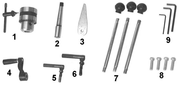
Shipping Contents
Unpack the carton and verify that all parts listed below are included.
Main Parts |
|
1 ea |
Head Assembly |
1 ea |
Table |
1 set Column and Table Bracket Assembly
1 ea |
Base |
|
Additional Parts |
||
1. |
1 set |
Chuck and Chuck Key |
2. |
1 pc |
Arbor |
3. |
1 pc |
Drift Key |
4. |
1 pc |
Table Crank Handle |
5. |
1 pc |
Table Lock Handle |
6. |
1 pc |
Column Lock Handle |
7. |
3 pcs |
Downfeed Handles and Knobs |
8. |
4 pcs |
M10 x 40 Hex Cap Screws |
9. |
1 set |
Hex Wrenches (3mm, 5mm, 6mm) |
Other Material
1 ea |
Owner’s Manual |
1 ea |
Warranty Registration Card |
Required Tools
1.17mm Box Wrench or a 6” – 8” Adjustable Wrench
2.15/16" wrench
Additional Parts
7
Assembly
Read and understand all assembly instructions before attempting assembly! Failure to comply may cause serious injury!
Before Assembly
1.Remove the contents from the shipping container.
2.Compare the contents of the shipping container with the list found above. Report any shortages or damage to your JET distributor.
3.Clean all rust protected surfaces with kerosene or a light solvent. Do not use lacquer thinner, paint thinner, or gasoline. These will damage plastic components and painted surfaces.
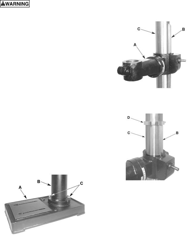
Column Assembly
Referring to Figure 1:
1.Place the base (A) on a level floor.
2.Place the column assembly (B) on the base
(A)and align the holes in the column support with the holes in the base.
Note: The column shown in Figure 1 is for the JDP-15MF. While the JDP-15M column is slightly different in appearance, the assembly procedure is the same.
3.Using a 17mm wrench, secure the column
(B) with four M10 x 40 hex cap screws (C) to the base.
Figure 1
Table Bracket
When shipped, the rack ring and rack are bundled together with the column in plastic wrap.
Referring to Figures 2 and 3:
4.Remove the wrap and take the rack ring (D) and rack (B) off the column (C).
5.Install the table bracket (A) together with the rack (B) as shown in Figure 2.
Figure 2
6.Slide the rack ring (D) over the column (C), placing it so it rests against the rack (B) as shown in Figure 3 and tighten firmly.
Figure 3
Crank Handle and Table Lock Handle
Referring to Figure 4 (shown already assembled):
1.Loosen the setscrew (B) on the table crank handle (A).
2.Slide the handle (A) onto the table bracket shaft.
3.Turn the handle until the setscrew is opposite the flat section on the shaft, and tighten the setscrew to secure the handle.
4.Install the table lock handle (C), but do not tighten.
8
Loading...