

Page 1
MSR3012
MARINE AUDIO SYSTEM
Installation and Operation Manual
Manual de la Instalación y Operación / Guide d'installation et d'opération
Manual de la Instalación y Operación / Guide d'installation et d'opération
Page 2

CONTENTS
Introduction......................................................................................................... 1
Safety Information .............................................................................................. 2
Installation........................................................................................................... 3
Wiring................................................................................................................... 4
Basic Operation .................................................................................................. 5
Tuner Operation.................................................................................................. 7
CD Player Operation........................................................................................... 8
MP3/WMA Operation.......................................................................................... . 9
SiriusXM Radio Operation................... ..................................... ........................ 11
iPod Operation.................................................................................................. 14
Care and Maintenance................................................ .................................... .. 15
Troubleshooting................... .. ........................................................................... 15
Specifications ............................................... ... ................................................. 16
MSR3012
Copyrights and Trademarks
iPhone, iPod, iPod classic, iPod nano, iPod shuffle, and iPod touch are trademarks of Apple
Inc., registered in the U.S. and other countries.
“Made for iPod” and “Made for iPhone” mean that an electronic accessory has been designed
to connect specifically to iPod or iPhone respectively, and has been certified by the developer
to meet Apple performance standards. Apple is not responsible for the operation of this device
or its compliance with safety and regulatory standards. Please note that the use of this
accessory with iPod or iPhone may affect wireless performance.
Sirius, XM and all related marks and logos are trademarks of Sirius XM Radio Inc. and its
subsidiaries. Visit www.xmradio.com/xmlineup for updates. All programming/channel lineup/
XM service subject to change or preemption. All other marks and logos are the property of their
respective owners. All rights reserved.
Important Legal Notice About Your SiriusXM Subscription
Hardware, subscription and activation fee required. Other fees and taxes will apply. Hardware
and subscription sold separately. Service automatically renews for additional periods of the
same lenqth as the Plan you choose, at the then current renewal rate unless you call to cancel.
Pricing and programming subject to change. Subscription governed by, as applicable, Sirius
Terms & Conditions (see www.sirius.com) or XM Customer Agreement (see
www.xmradio.com). SiriusXM U.S. Satell ite Servi ce available only to those at least 18 years of
age in the 48 contiguous USA and DC, with Sirius also available in PR (with coverage
limitations), while SiriusXM Internet Radio is available throughout our satellite service area and
also in AK and HI.
Important Legal Notice About Installation
Installation instructions are provided for your convenience. You must determine if you have the
knowledge, skills, and ability required to properly perform installation. Professional installation
is recommended. SiriusXM shall have no liability for damage/injury resulting from the
installation/use of any SiriusXM or other products. You must ensure that all products are
installed in adherence with local laws and regulations and in such a manner as to allow a
vehicle to be operated safely and without distraction. SiriusXM product warranties do not cover
the installation, removal, or reinstallation of any product.
ii
Page 3
MSR3012
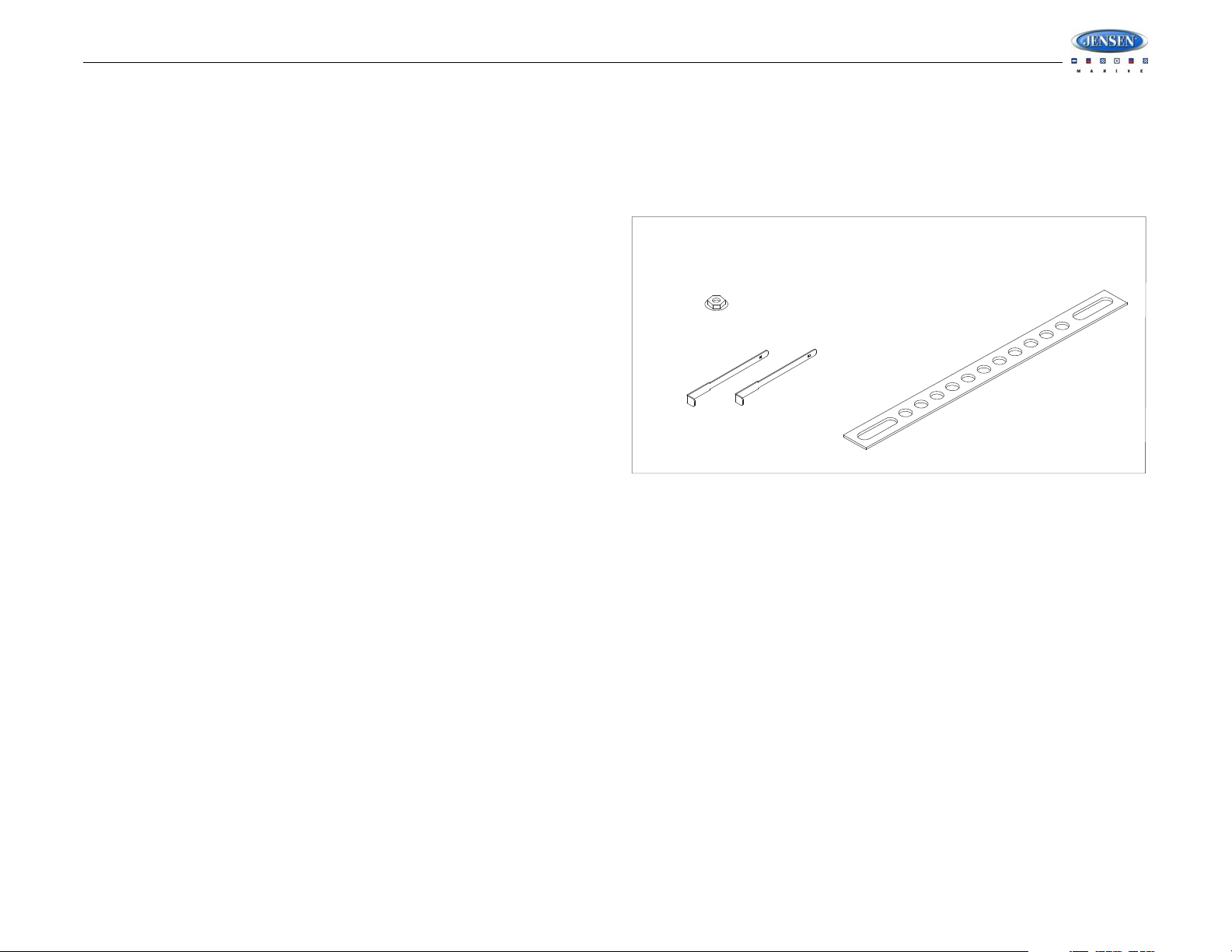
REMOVAL TOOL
MOUNTING STRAP
DIN SLEEVE
FLANGE NUT
HARDWARE KIT CONTENTS
INTRODUCTION
System Features
Features of the Jensen MSR3012 mobile audio system include:
• Full Dot Matrix LCD
• AM/FM US/EURO Tuner with 30 Presets (12 AM, 18 FM)
• SiriusXM Radio Ready
• Single In-Dash CD Player with MP3/WMA Playback Capability
• USB Playback of MP3 and WMA files
• CD ESP (Electronic Skip Protection) 30 Sec.
• iPod Ready (USB interface)
•Mute
• Pre-set Equalizer - 5 settings (USER > FLAT > POP > CLASSIC > ROCK)
• Electronic Bass, Treble, Balance and Fader Controls
• Output Power 40W x 4
• Wireled Remote Control Ready (MWR100 sold separately)
• 2-Channel Pre-amp Line Level Outputs
• Auxiliary Audio Input (Front 3.5mm Stereo Jack, Rear RCA)
Content List
• Jensen MSR3012 Radio
• Wire Harness
• Hardware Kit
• Owner’s Manual
1
Page 4
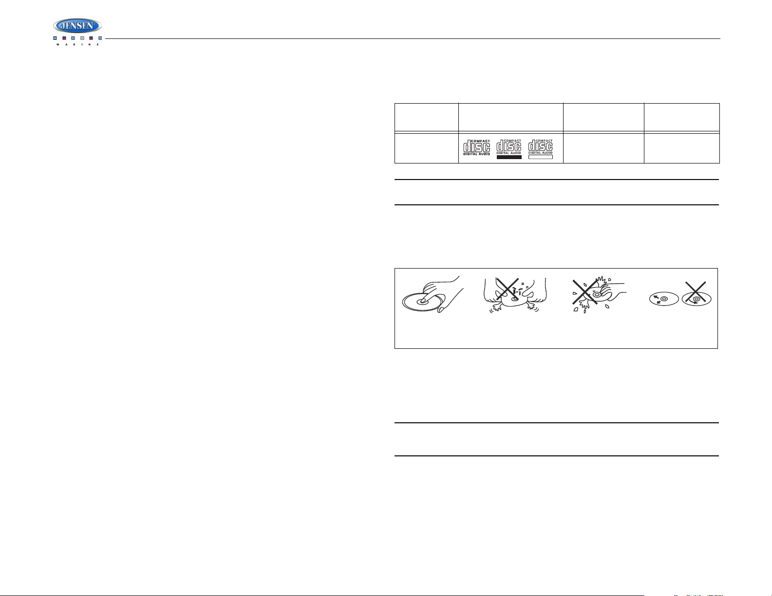
SAFETY INFORMATION
REWRITABLE
RECORDABLE
Insert label Do not bend.
Never touch
the under side
of the disc.
Wipe clean from
the center to the
edge.
side up.
When Boating
Keep the volume level Iow enough to be aware of your surroundings.
Protect from Water
Do not expose the product directly to water, as this can cause electrical shorts, fire or other
damage.
Protect from High Temperatures
Exposure to direct sunlight for an extended period of time can produce very high temperatures
inside your vessel. Give the interior a chance to cool down before starting playback.
Do not mount radio within close proximity of engine compartment.
Use the Proper Power Supply
This product is designed to operate with a 12 volt DC negative ground battery system.
Protect the Disc Mechanism
Avoid inserting any foreign objects into the disc slot. Misuse may cause malfunction or
permanent damage due to the precise mechanism of this unit.
CAUTION:
THIS MOBILE CD PLAYER IS A CLASS I LASER PRODUCT. THIS UNIT USES A VISIBLE/
INVISIBLE LASER BEAM WHICH COULD CAUSE HAZARDOUS RADIATION IF EXPOSED
DIRECTLY. BE SURE TO OPERATE THE MOBILE CD PLAYER AS INSTRUCTED.
USE OF CONTROLS OR ADJUSTMENTS OR PERFORMANCE OR PROCEDURES OTHER
THAN THOSE SPECIFIED HEREIN MAY RESULT IN HAZARDOUS RADIATION
EXPOSURE.
DO NOT OPEN COVERS AND DO NOT REPAIR BY YOURSELF. PLEASE REFER
SERVICING TO A QUALIFIED TECHNICIAN.
WARNING:
• TO REDUCE THE RISK OF FIRE OR ELECTRIC SHOCK, DO NOT EXPOSE THIS
EQUIPMENT DIRECTLY TO WATER.
• TO REDUCE THE RISK OF FIRE OR ELECTRIC SHOCK AND INTERFERENCE, USE
ONLY THE RECOMMENDED ACCESSORIES.
DISC NOTES
Depending on the recording status, conditions of the disc, and the equipment used for
recording, some CD-Rs/CD-RWs may not play on this unit. For more reliable playback, please
adhere to the following recommendations:
• Use CD-RWs with speed 1x to 4x and write with speed 1x to 2x.
• Use CD-Rs with speed 1x to 8x and write with speed 1x to 2x.
• Do not play a CD-RW which has been written more than 5 times.
MSR3012
Compatible Disc Types
Table 1: General Disc Information
Disc Type Logo
Audio CD 12 cm single side 74 minutes
NOTE: CD-R and CD-RW discs will not play unless the recording session is closed and
the CD is finalized.
Disc Maintenance
• A dirty or defective disc may cause sound dropouts while playing. Before playing, wipe
the disc using a clean cloth, working from the center hole towards the outside edge.
Never use benzene, thinners, cleaning fluids, anti-static liquids or any other solvent.
• Be sure to use only round CDs for this unit and do not use any special shape CDs. Use of
special shape CDs may cause the unit to malfunction.
• Do not stick paper or tape on the disc. Do not use CDs with labels or stickers attached or
that have sticky residue from removed stickers.
• Do not expose discs to direct sunlight or heat sources.
NOTE: A disc may become scratched (although not enough to make it unusable)
depending on how you handle it and other conditions in the usage environment. These
scratches are not an indication of a problem with the player.
Diameter/
Playable Sides
Playback Time
2
Page 5
MSR3012
182
53
Dashboard
Bend Tabs
Screw Stud
Dashboard
Plain Washer
Screw (5 x 25mm)
Hex Nut (5mm)
Spring Washer
Screw Stud
Support Strap
Removal Key
Sleeve
Removal Key
M
O
D
E
S
E
L
VO
LU
M
E
C
A
T
C
AT
VO
LU
M
E
M
SR
3012
INSTALLATION
Before You Begin
1. Disconnect Battery
2. Remove Transport Screws
Important Notes
• Before final installation, test the wiring connections to make sure the unit is connected
• Use only the parts included with the unit to ensure proper installation. The use of
• Consult with your nearest dealer if installation requires the drilling of holes or other
• Install the unit where it does not interfere with driving and cannot injure passengers if
• If the installation angle exceeds 30º from horizontal, the unit might not give optimum
• This unit is not waterproof and is intended for interior mounting applications only.
• Avoid installing the unit where it will be subject to high temperatures from direct sunlight,
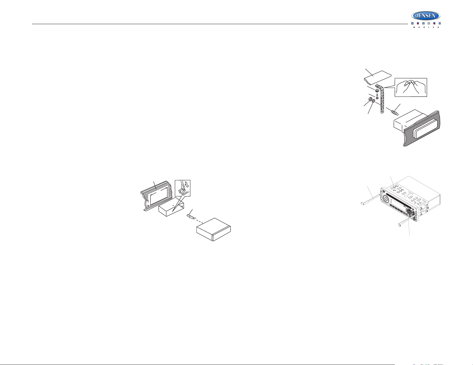
DIN Front Mount
1. Slide the mounting sleeve off of the chas-
2. Check the dashboard opening size by
3. Locate the series of bend tabs along the top, bottom and sides of the mounting sleeve.
4. Place the radio in front of the dashboard opening so the wiring can be brought through the
5. Follow the wiring diagram carefully and make certain all connections are secure and
6. After completing the wiring connections, turn the unit on to confirm operation (vessel
Before you begin, always disconnect the battery negative terminal.
properly and the system works.
unauthorized parts can cause malfunctions.
modifications to your vessel.
there is a sudden or emergency stop.
performance.
Exterior mounting of the unit requires use of an ASA approved marine housing.
hot air, or from a heater, or where it would be subject to excessive dust, dirt or vibration.
sis if it has not already been removed. If it
is locked into position, use the removal
keys (supplied) to disengage it. The
removal keys are depicted in “Removing
the Unit” on page 3.
sliding the mounting sleeve into it. If the
opening is not large enough, carefully cut
or file as necessary until the sleeve easily
slides into the opening. Do not force the
sleeve into the opening or cause it to bend
or bow. Check that there will be sufficient
space behind the dashboard for the radio chassis.
With the sleeve fully inserted into the dashboard opening, bend as many of the tabs
outward as necessary to firmly secure the sleeve to the dashboard.
mounting sleeve.
insulated with crimp connectors or electrical tape to ensure proper operation.
accessory switch must be on). If the unit does not operate, recheck all wiring until the
problem is corrected. Once proper operation is achieved, turn the accessory switch off
and proceed with final mounting of the chassis.
7. Carefully slide the radio into the mounting sleeve, making sure it is right-side-up, until it is
fully seated and the spring clips lock it into place.
8. Attach one end of the
perforated support strap
(supplied) to the screw stud on
the rear of the chassis using
the hex nut and spring washer
provided. Fasten the other end
of the perforated strap to a
secure part of the dashboard
either above or below the radio
using the screw and plain
washer provided. Bend the
strap, as necessary, to position
it. CAUTION: The rear of the
radio must be supported with
the strap to prevent damage to
the dashboard from the weight
of the radio or improper
operation due to vibration.
9. Test radio operation by referring to the operating instructions for the unit.
Removing the Unit
To remove the radio after installation, pull back
the rubber covers, insert the removal keys
straight back until they click, and then pull the
radio out. If removal keys are inserted at an
angle, they will not lock properly to release the
unit.
Reconnect Battery
When wiring is complete, reconnect the battery
negative terminal.
3
Page 6
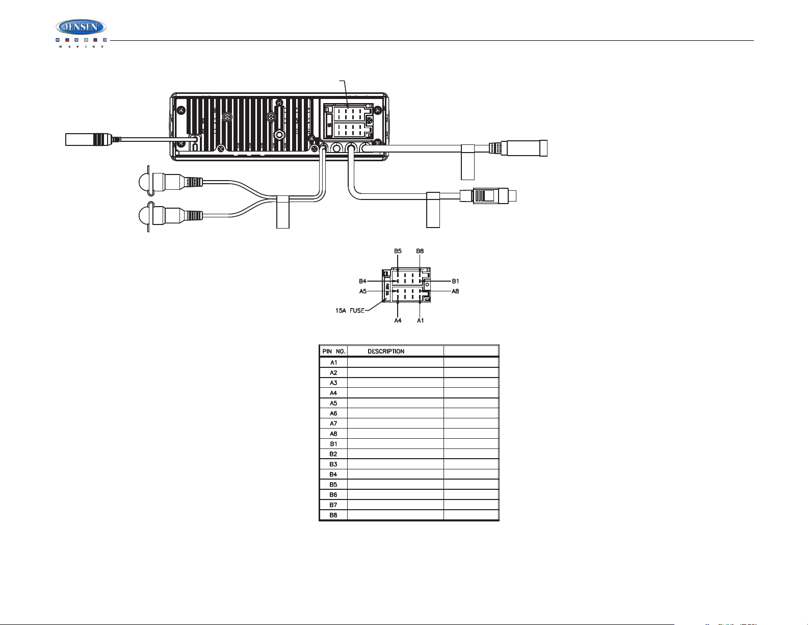
WIRING
Chassis Ground
Connect to ground terminal or clean
unpainted metal part of chassis.
12V TURN ON
Connect to existing radio wire/fuse.
Power Antenna
Connect to power antenna or amplifier.
If not used, tape bare end of wire.
RIGHT REAR SPEAKER (+)
RIGHT FRONT SPEAKER (+)
LEFT FRONT SPEAKER (+)
LEFT REAR SPEAKER (+)
LEFT REAR SPEAKER (-)
LEFT FRONT SPEAKER (-)
RIGHT FRONT SPEAKER (-)
RIGHT REAR SPEAKER (-)
NO CONNECTION
NO CONNECTION
POWER ANTENNA
NO CONNECTION
GROUND
NO CONNECTION
+12V SWITCHED
NO CONNECTION
VIOLET
GRAY
WHITE
GREEN
GREEN/BLACK
WHITE/BLACK
GRAY/BLACK
VIOLET/BLACK
EMPTY
EMPTY
BLUE
EMPTY
BLACK
EMPTY
RED
EMPTY
DETAILA
SHOWN FROM PIN VIEW
WIRE COLOR
FEMALE MOTOROLA TYPE
ANTENNA CONNECTOR
RED FEMALE
RCA CONNECTOR
WHITE FEMALE
RCA CONNECTOR
WIRED REMOTE CONNECTOR
SEE DETAILA
SiriusXM
CONNECTOR
BLACK
BLACK
BLACK
BLACK
SiriusXM
WIRED REMOTE
REAR RCA LINE-OUT
MSR3012
4
Page 7

3
2a
4
5
11
6
12
7
13
8
14
15
9
16
10
17
18
19
1
24
25
20
22
23
21
2b
MSR3012
BASIC OPERATION
Power On/Off
Press any button on the front panel to turn the unit on. Press the POWER button (1) to turn the
unit off.
• If a disc is being inserted when the radio power is off and the ACC (accessory switch) is
on, the unit will automatically power up and playback will start.
• If a CD is present, playback resumes at the last position in memory before the ignition
was turned off or the POWER button was pressed.
• If no CD is present, the unit will resume at the last mode selected (Tuner, Aux, etc.). The
POWER button is illuminated whenever the IGN lead (red wire) is powered, regardless of
whether the unit is on or off.
Volume Control
To increase the volume, press the VOLUME + button (2a). To decrease the volume, press the
VOLUME - button (2b).
Mute
Press the MUTE button (17) on the control panel to mute the audio output. Press MUTE again
to restore the audio output to the previous level.
Mode
Press the MODE/SEL button (4) on the control panel to select a different mode of operation, as
indicated on the display panel. Available modes include Tuner, SiriusXM, CD, iPod and AUX In
(optional Auxiliary Input).
NOTE: CD, IPOD, AUX or SIRIUSXM mode will be skipped if the module is not installed.
Reset
The reset button should be activated for the following reasons:
• initial installation of the unit when all wiring is completed
• function buttons do not operate
• error symbol on the display
Use a ball point pen or similar object to press the RESET button (18). This may be necessary
should the unit display an error code.
You can recover factory default settings using the RESUME function located on the system
menu. With “YES” flashing, press the MODE/SEL button (4) to activate.
Audio Menu
Press the AUDIO/MENU button (3) on the control panel to access the audio menu. You can
navigate through the audio menu items by pressing the AUDIO/MENU button repeatedly. Once
the desired menu item appears on the display, adjust that option by pressing the VOLUME +/buttons (2) within 5 seconds. The unit will automatically exit the audio menu after five seconds
of inactivity. The following menu items can be adjusted.
Bass Level
Use the VOLUME buttons to adjust the Bass level range from “-6” to “+6”.
Treble Level
Use the VOLUME buttons to adjust the Treble level range from “-6” to “+6”.
Balance
Use the VOLUME buttons to adjust the Balance between the left and right speakers from “L12”
(full left) to “R12” (full right).
Fader
Use the VOLUME buttons to adjust the Fader between the rear and front speakers from “R12”
(full rear) to “F12” (full front).
Volume Level
Use the VOLUME buttons to adjust the Volume level.
System Menu
1. Press and hold the AUDIO/MENU button (3) for more than 3 seconds to enter the system
menu. “MENU” will appear on the display, followed by the first menu item, “CONTRAST.”
2. Press the TUNE/TRK >>| or |<< button (21, 20) or press the AUDIO/MENU button
repeatedly to navigate the system menu and select the desired item.
3. Press the VOLUME +/- buttons (2) to adjust the selected menu item.
4. Press the AS/PS button (15) to return to the previous operation immediately or wait for 5
seconds to return automatically.
The following items can be adjusted:
• CONTRAST (0 – 10): Set LCD contrast.
• LOW BATT (ON/OFF): Monitor voltage on ACC line.
• Local/Distant: “Local” mode favors access to local stations whose signals are much
stronger, thereby improving reception. Select “Distant” to terminate local receive mode
and resume normal mode.
• AREA (U.S.A./LATIN/EUROPE): Set frequency spacing for various regions.
• VOL PGM (0 – 46): Select an automatic turn-on volume.
• BEEPTONE (ON/OFF): Turn the audible beep ON/OFF (heard when functions/buttons
are selected). NOTE: Beep tone off will not affect LOW BATT audible tone.
• SXM CH LOCK (when SiriusXM tuner is present): Set and manage a 4-digit parental lock
code to restrict mature content. Press the MODE/SEL button (4) to view “P-LOCK”. Use
5
Page 8

the VOLUME +/- buttons (2) to choose digits from 0 to 9. Press the MODE/SEL button to
enter and move to the next digit. The default code is “0000”.
• RESET: Return the EEPROM to factory default set up values. "Yes" will blink on the LCD
to confirm. Press MODE to select.
LOW BATTERY Operation
If LOW BATT is set to “ON”, an alarm will sound (8 beeps every 30 sec) when the voltage
drops to 10.8V (+/- 0.03V). A visual warning (LOBA) will appear flashing (8 flashes every 30
sec) in the lower left corner of the LCD display.
NOTE: “OFF” is the default setting for LOW BATT. If the audio is muted or the volume is
set to 0, the audible beep will not be heard.
Equalizer
Press the EQ/LOUD button (11) to turn on the equalization function and select between five
pre-defined bass and treble curves: USER > FLAT > POP > CLASSIC > ROCK.
Loudness
Press and hold the EQ/LOUD button (11) to toggle true loudness on/off. When listening to
music at low volumes, this feature will boost the bass and treble ranges to compensate for the
characteristics of human hearing.
Auxiliary Input
To access an auxiliary device:
1. Connect the portable audio player to the AUX IN on the front panel (19).
2. Press the MODE button (4) to select Aux In mode.
3. Press MODE again to cancel Aux In mode and go to the next mode.
Liquid Crystal Display (LCD)
The current frequency and activated functions are shown on the LCD panel (23).
MSR3012
NOTE: LCD panels may take longer to respond when subjected to cold temperatures for
an extended period of time. In addition, the visibility of the numbers on the LCD may
decrease slightly. The LCD display will return to normal when the temperature increases
to a normal range.
Scroll
When the information is too long to be displayed on the LCD, press and hold the SCROLL/
INFO button (12) to view the entire title. The information will scroll twice and then return to
abbreviated text.
Quick Exit Hot Key
In the following modes and conditions, press the AS/PS button (15) < 3 seconds to quickly exit
the current operation without waiting for the system default time out:
• System menu operation
• Searching mode
• Audio menu operation
6
Page 9

MSR3012
3
2a
4
5
11
6
12
7
13
8
14
15
9
16
10
17
18
19
1
24
25
20
22
23
21
2b
TUNER OPERATION
Select a Band
Press the BAND/SEARCH button (16) to change between three FM bands and two AM (MW)
bands.
Manual Tuning
Press the SEEK/TUNE/TRK |<< or >>| buttons (20, 21) to seek stations up/down step by step.
Auto Seek Tuning
Press and hold the SEEK/TUNE/TRK |<< or >>| buttons (20, 21) to automatically seek the next
or previous strong station.
Preset Stations
Six numbered preset buttons store and recall stations for each band.
Store a Station
Select a band (if needed), then select a station. Press and hold a preset button (5-10) for two
seconds. The preset number will appear in the display.
Recall a Station
Select a band (if needed). Press a preset button (5-10) to select the corresponding stored
station.
Automatically Store / Preset Scan (AS/PS)
Automatically Store
Select a band (if needed). Press and hold the AS/PS button (15) for more than three seconds
to automatically select six strong stations and store them in the current band. The new stations
replace any stations already stored in that band.
Preset Scan
Select a band (if needed). Press the AS/PS button (15) to scan stations stored in the current
band. The unit will pause for ten seconds at each preset station. Press AS/PS again to stop
scanning when the desired station is reached.
NOTE: During Auto Store (AS), the tuner will default to “Local” mode while scanning the
band initially. After scanning the entire band once, the unit will switch to “Distant” mode
for all subsequent Auto Store tuning.
7
Page 10

CD PLAYER OPERATION
3
2a
4
5
11
6
12
7
13
8
14
15
9
16
10
17
18
19
1
24
25
20
22
23
21
2b
Inserting and Ejecting a Disc
Insert a disc, label-side up, into the disc slot (24) with the unit turned on. The unit will
automatically draw the disc in and play the first track on the disc.
Press the eject button (22) to stop disc play and eject the disc. The unit does not have to be
turned on to eject the disc.
Controlling Disc Playback
Selecting Tracks
Press the SEEK/TUNE/TRK >>| (21) or SEEK/TUNE/TRK |<< button (20) to advance to the
next track on the CD. The selected track number will appear on the display. Press and hold the
SEEK/TUNE/TRK >>| or |<< button to fast forward or fast reverse through the disc. CD play
starts when the button is released.
Play/Pause Disc Playback
Press the 1/>|| button (8) to suspend disc play. Press the 1/>|| button again to resume disc
Play.
Previewing Tracks
Press the 2/INT button (6) to play the first 10 seconds of each track sequentially. Press 2/INT
again to stop Intro Scan and resume normal play at the current track.
Repeat Play
Press the 3/RPT button (5) during disc play to repeat play the current track. Press 3/RPT again
to stop repeat play.
Random Play
Press the 4/RDM button (7) during disc play to play all tracks on a CD in random, shuffled
order. Press 4/RDM again to stop random play.
MSR3012
8
Page 11

3
2a
4
5
11
6
12
7
13
8
14
15
9
16
10
17
18
19
1
24
25
20
22
23
21
2b
MSR3012
MP3/WMA OPERATION
MP3/WMA File Requirements
The MP3/WMA recording media acceptable to this unit are CD-ROM, CD-R and CD-RW.
When using CD-RW, use full format rather than quick format to prevent malfunction. Discs
written by Packet Write (UDF) are not supported.
This unit can play MP3 (MPEG1, 2, 2.5 Audio Layer 2/3) and WMA (version 7/8/9).
Media Requirements
The following formats are available for the media used in this unit. The maximum number of
characters used for file name including the delimiter (".") and three-character extension are
indicated in parentheses.
• ISO 9660 Level 1 (11 characters)
• ISO 9660 Level 2 (31 characters)
• Joliet (31 characters)
• Romeo (31 characters)
The media reproducible on this unit has the following limitations:
• Maximum number of nested folders: 8
• Maximum number of files per disc: 999
• Maximum number of folders per disc: 99
Use the following settings when compressing audio data in MP3 data with the MP3 encoder.
• Transfer bit rate: 32 - 320 kbps
• Sampling frequency
• MPEG1: 32/44.1/48 KHz
• MPEG2:16/22.05/24 KHz
• MPEG2.5: 8/11.025/12KHz
• WMA: 22/32/44/48KHz
When using a CD writer to record MP3/WMA up to the maximum disc capacity, disable
additional writing. To record an empty disc up to the maximum capacity at once, select the
“disc at once” option. This unit supports multi-session recording.
• Maximum length of file name: 28 characters
• Maximum length of directory: 16 characters
• Maximum file/directory name: 64 bytes
ID3 Support
This unit supports ID3 tag versions 1.0. 1.1, 2.0 and 2.3 (Max 32 bytes).
Insert and Eject Disc
Insert a disc, label-side up, with the unit turned on. After the disc scan is complete, the unit will
play the first track on the disc. The MP3 icon is illuminated during MP3 playback. Press the
eject button (22) to stop disc play and eject the disc. The unit does not have to be turned on
to eject the disc.
Installing a USB Device
Insert your USB thumb drive into the USB slot (25) on the front of the radio. The unit will
automatically search for MP3 and WMA files on the device and begin playback. You can
access USB mode from any other mode by pressing the MODE/SEL button (4).
WARNING: Do not remove the device when USB PLAY mode is active. Press MODE/SEL
(4) to change to another mode before removing the device.
Controlling Playback
Pause
Press the 1 >/|| button (8) to suspend disc play. Press the 1 >/|| button again to resume play.
Track Select
Press the SEEK/TUNE/TRK >>| (21) or |<< (20) button for less than one second to advance to
the next file, or press and hold to fast forward or fast reverse. Playback begins when the button
is released.
Intro Scan (INT)
Press the 2 INT button (6) once to play the first 10 seconds of each file in the current folder.
Press 2 INT again to play the first 10 seconds of each file on the current disc. When the
desired file is reached, press 2 INT a third time to end the scan and play the selected file.
Repeat (RPT)
Press the 3 RPT button (5) to repeatedly play the current file. Press 3 RPT again to repeat all
songs in the current folder. Press 3 RPT a third time to resume normal playback.
Random (RDM)
Press the 4 RDM button (7) to randomly play all files in the current folder. Press 4 RDM again
to randomly play all files on the disc. Press 4 RDM a third time to resume normal playback.
Navigating Folders
Press the 5 button (9) to move to the previous folder.
Press the 6 button (10) to advance to the next folder.
9
Page 12

MP3/WMA Directory Search
1. Press BAND/SEARCH button (16) to enter directory search mode.
2. Press the MODE/SEL button (4) to confirm search mode. The LCD will display the folder
list.
3. Navigate the folder list by pressing the VOLUME +/- buttons (2).
4. Press the MODE/SEL button to select a folder. The LCD will display the list of files within
that folder.
5. Navigate the file list by pressing the VOLUME +/- buttons.
6. Press the MODE/SEL button to select a file.
MSR3012
10
Page 13

MSR3012
3
2a
4
5
11
6
12
7
13
8
14
15
9
16
10
17
18
19
1
24
25
20
22
23
21
2b
SiriusXM RADIO OPERATION
Activating Your Service
1. With the radio still turned on, tune to the SiriusXM preview channel on Channel 1. You
should be able to hear the SiriusXM preview channel even if your service is not activated.
If you cannot hear the preview channel, please check the installation instructions to make
sure your tuner is properly installed.
2. Visit www.siriusxm.com/activate or call SiriusXM Listener Care at 1-866-635-2349 to
activate your service.
NOTE: As part of the activation process, the SiriusXM satellites will send an activation
message to your tuner (see “Advisory Messages Reported by the SiriusXM Vehicle
Tuner” on page 13). When your radio detects that the tuner has received the activation
message, your radio will display: “Subscription Updated”. Once subscribed, you can
tune to channels in your subscription plan. Note, the activation process usually takes
10 to 15 minutes, but may take up to an hour. Your radio will need to be powered on and
receiving the SiriusXM signal to receive the activation message.
About SiriusXM
Everything worth listening to is on SiriusXM. Get over 130 channels, including the most
commercial-free music, plus the best sports, news, talk and entertainment. A SiriusXM Tuner
and Subscription are required. For more information, visit www.siriusxm.com.
NOTE: The SiriusXM Satellite Radio controls on this unit are available only when a
SiriusXM Tuner is connected.
Switching to SiriusXM Mode
Press the MODE/SEL button (4) to change the mode to SiriusXM radio mode.
Accessing your SiriusXM ID
To subscribe to the SiriusXM Satellite Radio service, it is necessary to locate and identify the
Radio ID of your SiriusXM Tuner.
1. In SiriusXM mode, press and hold the BAND/SEARCH button (16) to select DIRECT
mode.
2. Press the MODE/SEL button (4) to activate Direct mode.
3. Press the MODE/SEL button for each digit to enter “000”.
4. Press MODE/SEL again to confirm. This will display the SiriusXM ID number for your
tuner.
5. The SiriusXM ID number will scroll twice and then freeze with the first 11 digits on the
display. Press the SCROLL/INFO button (12) to display the remaining digit.
6. Write down the number for reference.
Radio ID: _____________________________________________________________
NOTE: The SiriusXM Radio ID does not include the letters I, O, S or F.
Selecting a Band
In SiriusXM mode, press the BAND/SEARCH button (16) to access the SiriusXM user-preset
channel groups in the following order: SAT-1, SAT-2, SAT-3.
Category Tuning
1. Press the CAT - /+ buttons (13/14) to change the category. Each category title will be displayed in increments.
2. While in the category mode, press the CAT - /+ buttons again to view category names.
(The lowest channel number within the chosen category will always be the default first
channel tuned.)
3. Press the MODE/SEL button (4) to select the current channel or the SEEK/TUNE/TRK
|<< / >>| buttons (20/21) to choose channels in that category.
4. Press the SEEK/TUNE/TRK buttons to select a channel within the chosen category.
5. Press MODE/SEL to confirm channel selection.
Channel Up/Down Tuning
Press the SEEK/TUNE/TRK |<< / >>| buttons (20/21) to search for a channel. Press and hold
the SEEK/TUNE/TRK buttons to rapid search.
Storing Preset Channels
The preset buttons (5-10) can be used to store 6 channels, allowing convenient access to your
favorite channels.
Programming Channels
1. Select the channel you want to store in preset memory.
2. Press and hold a preset button (5-10) until the corresponding preset button number
appears.
3. Repeat steps 1 and 2 to program additional channels.
Recalling Preset Channels
Press one of the six preset buttons (5-10) to select a preset channel directly.
11
Page 14

Channel Direct Access Searching
Signal Strength Strength Display
No Signal
Weak
Good
Excellent
1. Press and hold the BAND/SEARCH button (16) to access Direct Tune mode. “DIRECT-T”
appears on the display for a few seconds.
2. Press the MODE/SEL button (4) to confirm.
3. Use the VOLUME +/- buttons (2) to select a number for each position and move to the
next digit.
4. Press the MODE/SEL button to confirm each digit.
5. Press the MODE/SEL button again to tune to the selected file.
Parental Lock
Set and manage a 4-digit parental lock code to restrict mature content.
1. Press and hold the AUDIO/MENU button (3) for more than 3 seconds to enter the system
menu.
2. Press the TUNE/TRK >>| or |<< button (21, 20) navigate to the “SXM SETUP MENU”
feature.
3. Press the MODE/SEL button (4) to view “P-LOCK”.
4. Use the VOLUME +/- buttons (2) to choose digits from 0 to 9. The default code is “0000”.
5. Press the MODE/SEL button to enter and move to the next digit.
Alternate Display Information
Press SCROLL/INFO button (12) to change the display information in the following order:
ARTIST NAME > SONG TITLE > CONTENT (if available) > CATEGORY > CHANNEL NAME.
Satellite Signal Strength
The display will indicate satellite reception strength as shown below.
MSR3012
12
Page 15

MSR3012
Advisory Messages Reported by the SiriusXM Vehicle Tuner
Table 1: SiriusXM Advisory Messages
On-Screen Display Advisory Message Cause Explanation/Solution
Chk Antena Check Antenna The radio has detected a fault with the SiriusXM antenna. The
Check Tuner Check Tuner • The radio is having difficulty communicating with the SiriusXM
No Signal No Signal The SiriusXM Connect Vehicle Tuner is having dif ficulty receiving
Scrolling “Subscriptn
Updated” - press any key
to continue”
Ch Unavail Channel Not Available The channel that you have requested is not a valid SiriusXM
Chan Unsub Channel Not Subscribed The channel that you have requested is not included in your Siri-
Channel Locked Channel Locked The channel that you have requested is Locked by the radio
“Paging Lock Code?” followed by ****
Subscription Updated The radio has detected a change in your SiriusXM subscription
Enter Lock Code User prompted to enter the lock/ unlock code. Enter the four digit code to play the audio.
antenna cable is either disconnected or damaged.
Connect Vehicle Tuner.
• The tuner may be disconnected or damaged.
the SiriusXM satellite signal.
status.
channel or the channel that you were listening to is no longer
available. You may also see this message briefly when first connecting a new SiriusXM Connect Vehicle tuner. Visit www.siriusxm.com for more information about the SiriusXM channel
lineup.
usXM subscription package or the channel that you were listening
to is no longer included in your SiriusXM subscription package.
Parental Control feature.
• Verify that the antenna cable is connected to the SiriusXM
Connect Vehicle Tuner.
• Inspect the antenna cable for damage and kinks. Replace the
antenna if the cable is damaged.
• Verify that the SiriusXM Connect Vehicle Tuner cable is
securely connected to the radio SiriusXM mating connector/
cable.
• If the problem persists, disconnect and reconnect the tuner
and then contact your dealer.
• Verify that your vehicle is outdoors with a clear view of the
southern sky.
• Verify that the SiriusXM magnetic mount antenna is mounted
on a metal surface on the outside the vehicle.
• Move the SiriusXM antenna away from any obstructions.
• Inspect the antenna cable for damage and kinks. Replace the
antenna if the cable is damaged.
• If the problem persists, disconnect and reconnect the tuner
and then contact your dealer.
• Press Enter to clear the message.
• No further action is required.
• Visit www.siriusxm.com or call 1-866-635-2349 if you have
questions about your subscription.
Visit www.siriusxm.com or call 1-866-635-2349 if you have questions about your subscription package or would like to subscribe
to this channel.
See the section on Parental Control, page 45 for more information
on the Parental Control feature and how to access locked channels.
13
Page 16

iPod OPERATION
3
2a
4
5
11
6
12
7
13
8
14
15
9
16
10
17
18
19
1
24
25
20
22
23
21
2b
This unit is equipped with an iPod ready function that will allow you to control your iPod (if
compatible) using the control panel buttons. The following iPod versions are supported:
• iPod Nano (1G, 2G, 3G, 4G and 5G)
• iPod 5G
• iPod Classic
• iPhone, iPhone 3G, iPhone 3GS, iPhone 4
• iPod Touch
• iPod Touch 2G
NOTE: Earlier model iPods are not supported because they do not implement the USB
control protocol. Also, the iPod Shuffle is not supported because it does not utilize the
30-pin Apple iPod Connector. These unsupported iPod models may be connected to the
radio using one of the Auxiliary Inputs.
Accessing iPod Mode
MSR3012
NOTE: The iPod will continuously recharge when connected to the unit, as long as the
vehicle ignition is turned on.
Controlling Playback
Selecting Tracks
During playback, press the SEEK/TUNE/TRK |<< / >>| button (20/21) to play the previous or
next track in the current category. Press the SEEK/TUNE/TRK |<< button (20) once to play the
song from the start position or press SEEK/TUNE/TRK |<< twice to play the previous track.
Press and hold the SEEK/TUNE/TRK |<< / >>| button (20/21) to fast reverse/forward the song.
Pausing Playback
During playback, press the 1/>|| button (8) to pause the iPod player. “PAUSE” will appear on
the LCD. Press 1/>|| again to resume playback.
Repeat Play
During playback, press the 3/RPT button (5) to repeat the current song. “REPEA” will appear
on the LCD. Press 3/RPT again to stop repeat playback.
Random Play
During playback, press the 4/RDM button (7) to play all songs in the current category in
random order. Random play will begin once the current song has finished playing. “SHUFF” will
appear on the LCD. Press 4/RDM again to stop random playback.
NOTE: If you press and hold the SEEK/TUNE/TRK |<< / >>| button to change the current
song to the previous/next song, you will exit fast reverse/forward mode.
Connect a supported iPod or iPhone to the front panel USB connector. The iPod icon
illuminates in the bottom right corner of the LCD whenever an iPod or iPhone is attached to the
USB connector. Music playback begins automatically.
To enter iPod mode from any other source, press the MODE/SEL button (4) until “USB”
appears on the display. If the user connects an iPod containing no songs, the radio will
display a message stating “No Songs” when it enters iPod mode.
Turning the iPod On/Off
The iPod power turns on automatically when an iPod is connected to the front panel USB
connector, as long as the vehicle ignition is turned on. You can turn the iPod off by
disconnecting it or by turning the ignition off. When the ignition is turned off, the iPod will pause
and then enter sleep mode after 2 minutes. While the iPod is connected, the power cannot be
turned on or off from the iPod itself.
Alternate Display Information
Press the SCROLL/INFO button (12) to change the display information in the following order:
ARTIST NAME > SONG TITLE > FOLDER NAME.
Search Mode
Press the BAND/SEARCH button (16) repeatedly to enter iPod search mode and choose from
the following search criteria: Playlist, Artist, Album, Song, Genre or Composer (consecutively).
When search mode is selected, press the MODE/SEL button (4) to confirm selection. Use the
VOLUME +/- buttons (2) to navigate through various list selections. Press MODE/SEL (4) to
make your final selection.
14
Page 17

MSR3012
CARE AND MAINTENANCE
• Keep the product dry. If it does get wet, wipe it dry immediately. Liquids might contain
minerals that can corrode the electronic circuits.
• Keep the product away from dust and dirt, which can cause premature wear of parts.
• Handle the product gently and carefully. Dropping it can damage circuit boards and
cases, and can cause the product to work improperly.
• Wipe the product with a dampened cloth occasionally to keep it looking new. Do not use
harsh chemicals, cleaning solvents, or strong detergents to clean the product.
• Use and store the product only in normal temperature environments. High temperature
can shorten the life of electronic devices, damage batteries, and distort or melt plastic
parts.
Ignition
The most common source of noise in reception is the ignition system. This is a result of the
radio being placed close to the ignition system (engine). This type of noise can be easily
detected because it will vary in intensity of pitch with the speed of the engine.
Usually, the ignition noise can be suppressed considerably by using a radio suppression type
high voltage ignition wire and suppressor resistor in the ignition system. (Most vessels employ
this wire and resistor but it may be necessary to check them for correct operation.) Another
method of suppression is the use of additional noise suppressors. These can be obtained from
most CB/A radio or electronic supply shops.
Interference
Radio reception in a moving environment is very different from reception in a stationary
environment (home). It is very important to understand the difference.
AM reception will deteriorate when passing under a bridge or when passing under high voltage
lines. Although AM is subject to environmental noise, it has the ability to be received at great
distance. This is because broadcasting signals follow the curvature of the earth and are
reflected back by the upper atmosphere.
TROUBLESHOOTING
Symptom Cause Solution
No power The vessel’s accessory
Disc cannot be loaded or
ejected
No sound Volume is too low Adjust volume to audible level.
The operation keys do
not work
Sound skips Installation angle is more
Cannot tune to radio station, auto-seek does not
work
ERROR-01 on LCD Database or decoder error Change to another mode.
ERROR-02 on LCD Disc not supported Remove disc and insert supported
ERROR-03 on LCD No songs on device Remove device and add songs.
ERROR-04 on LCD Abnormal current to USB
ERROR-05 on LCD iPod/iPhone is not verified Unplug and reconnect iPod/
switch is not on
Fuse is blown Replace the fuse.
Presence of CD disc inside
the player
Inserting the disc in upside
down
Compact disc is extremely
dirty or disc is defective
Condensation Leave the player off for an hour or
Wiring is not properly connected
Control panel is not properly installed
Built-in microcomputer is
not operating properly due
to noise
than 30 degrees
Disc is dirty or defective Clean the disc and try to play
Antenna cable is not
connected
Signals are too weak Select a station manually.
device
If the power supply is properly
connected to the vessel’s accessory terminal, switch the ignition
key to “ACC”.
Remove the disc in the player and
insert the new one.
Insert the compact disc with the
label facing upward.
Clean the disc or try to play a new
one.
so, then try again.
Check wiring connections.
Reinstall control panel.
Press the RESET button.
Adjust the installation angle to
less than 30 degrees.
again or use a new disc.
Insert the antenna cable firmly.
CDDA or CD-ROM disc.
Change mode or unplug and reconnect USB device.
iPhone.
15
Page 18

SPECIFICATIONS
CD
Signal to Noise Ratio. . . . . . . . . . . . . . . . . . . . . . . . . . . . . . . . . . . . . . . . . . . . . . . . . >
Channel Separation . . . . . . . . . . . . . . . . . . . . . . . . . . . . . . . . . . . . . . . . . .: More than 50 dB
Frequency Response . . . . . . . . . . . . . . . . . . . . . . . . . . . . . . . . . . . . . . . . . . . 20 Hz - 20 kHz
FM Radio
Frequency Coverage (USA) . . . . . . . . . . . . . . . . . . . . . . . . . . . . . . . . . . . 87.5 to 107.9 MHz
Frequency Coverage (Europe) . . . . . . . . . . . . . . . . . . . . . . . . . . . . . . . . . . .87.5 to 108 MHz
Sensitivity (S/N=30dB) . . . . . . . . . . . . . . . . . . . . . . . . . . . . . . . . . . . . . . . . . . . . . . . . . . .4µV
Image Rejection . . . . . . . . . . . . . . . . . . . . . . . . . . . . . . . . . . . . . . . . . . . . . . . . . . . . .> 45 dB
Stereo Separation. . . . . . . . . . . . . . . . . . . . . . . . . . . . . . . . . . . . . . . . . . . . . . . . . . . .> 25 dB
AM/MW
Frequency Range (USA). . . . . . . . . . . . . . . . . . . . . . . . . . . . . . . . . . . . . . . . . 530-1710 kHz
Frequency Range (Europe). . . . . . . . . . . . . . . . . . . . . . . . . . . . . . . . . . . . . . . 522-1620 kHz
Sensitivity (S/N=20dB) . . . . . . . . . . . . . . . . . . . . . . . . . . . . . . . . . . . . . . . . . . . . . . . . . 36 dB
General
Operating Voltage . . . . . . . . . . . . . . . . . . . . . . . . . . . . . . . . . . . . . . . . . . . . . . . . .DC 12 Volts
Grounding System . . . . . . . . . . . . . . . . . . . . . . . . . . . . . . . . . . . . . . . . . . . Negative Ground
Speaker Impedance . . . . . . . . . . . . . . . . . . . . . . . . . . . . . . . . . . . . . . .4-8 ohms per channel
Tone Controls:
Bass (at 100 Hz) . . . . . . . . . . . . . . . . . . . . . . . . . . . . . . . . . . . . . . . . . . . . . . . . . . ±10 dB
Treble (at 10 kHz). . . . . . . . . . . . . . . . . . . . . . . . . . . . . . . . . . . . . . . . . . . . . . . . . . ±10 dB
Power Output . . . . . . . . . . . . . . . . . . . . . . . . . . . . . . . . . . . . . . . . . . . . . . . . . . . . . . 40W x 4
Current Drain. . . . . . . . . . . . . . . . . . . . . . . . . . . . . . . . . . . . . . . . . . . . . . . .15 Ampere (max.)
Chassis Dimensions . . . . . . . . . . . . . . . . . . . . . . . . . . . . . . . . . . . 182(L) x 52.2(W) x 173(H)
Front Panel Dimensions . . . . . . . . . . . . . . . . . . . . . . . . . . . . . . . . . . .188(L) x 58(W) x 21(H)
75 dB
MSR3012
16
 Loading...