

Page 1

JENN-AIR® 30", 36", AND 48" (76.2 CM, 91.4 CM,
AND 121.9 CM) COMMERCIAL STYLE WALL-
MOUNT CANOPY RANGE HOOD
HOTTE DE CUISINIÈRE JENN-AIR® DE STYLE
COMMERCIAL POUR POUR MONTAGE MURAL DE
30", 36" ET 48" (76,2 CM, 91,4 CM ET 121,9 CM)
LI3UNC/W10274316C
IMPORTANT: READ AND SAVE THESE INSTRUCTIONS.
FOR RESIDENTIAL USE ONLY.
IMPORTANT : LIRE ET CONSERVER CES INSTRUCTIONS.
POUR UTILISATION RÉSIDENTIELLE UNIQUEMENT.
Installation Instructions and Use & Care Guide
For questions about features, operation/performance, parts, accessories, or service in the U.S.A., call:
Instructions d’installation et Guide d’utilisation et d’entretien
Au Canada, pour assistance, installation ou service, composez le 1-800-JENNAIR (1-800-536-6247) ou visitez notre site web à
1-800-JENNAIR (1-800-536-6247) or visit our website at www.jennair.com.
In Canada, call: 1-800-JENNAIR (1-800-536-6247), or visit our website at www.jennair.ca.
www.jennair.ca.
Table of Contents/Table des matières ...................2
Page 2

TABLE OF CONTENTS
RANGE HOOD SAFETY .................................................................3
INSTALLATION REQUIREMENTS ................................................5
Tools and Parts ............................................................................5
Location Requirements................................................................5
Venting Requirements..................................................................7
Electrical Requirements ...............................................................8
INSTALLATION INSTRUCTIONS ..................................................8
Prepare Location..........................................................................8
Install Range Hood.......................................................................9
Install Range Hood Blower Motor................................................ 9
Make Electrical Connection .......................................................10
Complete Installation and Check Operation..............................11
RANGE HOOD USE......................................................................12
Range Hood Controls ................................................................12
RANGE HOOD CARE ...................................................................13
Range Hood Lamps...................................................................13
Cleaning......................................................................................13
WIRING DIAGRAM .......................................................................14
ASSISTANCE OR SERVICE.........................................................15
In the U.S.A. ...............................................................................15
In Canada ...................................................................................15
Accessories................................................................................15
WARRANTY ..................................................................................16
TABLE DES MATIÈRES
SÉCURITÉ DE LA HOTTE DE CUISINIÈRE................................17
EXIGENCES D'INSTALLATION...................................................19
Outillage et pièces......................................................................19
Exigences d'emplacement.........................................................19
Exigences concernant l'évacuation ...........................................21
Spécifications électriques ..........................................................22
INSTRUCTIONS D'INSTALLATION.............................................22
Préparation de l'emplacement...................................................22
Installation de la hotte ................................................................23
Installation du moteur du ventilateur de la hotte .......................23
Raccordement électrique...........................................................24
Achever l'installation et vérifier le fonctionnement ....................25
UTILISATION DE LA HOTTE .......................................................26
Commandes de la hotte de cuisinière .......................................26
ENTRETIEN DE LA HOTTE DE CUISINIÈRE .............................27
Lampes de la hotte de cuisinière ...............................................27
Nettoyage ...................................................................................28
SCHÉMAS DE CÂBLAGE ............................................................29
ASSISTANCE OU SERVICE.........................................................30
Au Canada..................................................................................30
Accessoires ................................................................................30
GARANTIE.....................................................................................31
2
Page 3
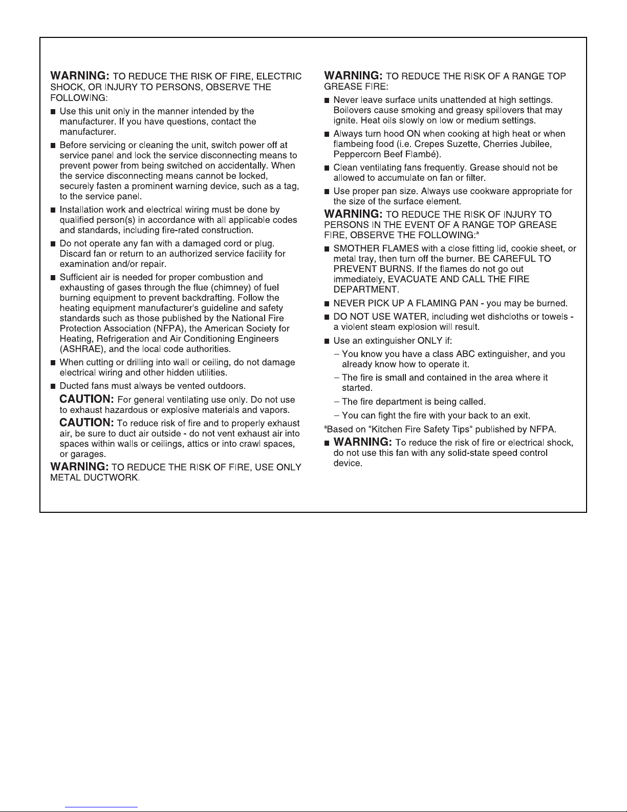
RANGE HOOD SAFETY
You can be killed or seriously injured if you don't immediately
You
can be killed or seriously injured if you don't
follow
All safety messages will tell you what the potential hazard is, tell you how to reduce the chance of injury, and tell you what can
happen if the instructions are not followed.
Your safety and the safety of others are very important.
We have provided many important safety messages in this manual and on your appliance. Always read and obey all safety
messages.
This is the safety alert symbol.
This symbol alerts you to potential hazards that can kill or hurt you and others.
All safety messages will follow the safety alert symbol and either the word “DANGER” or “WARNING.”
These words mean:
follow instructions.
instructions.
DANGER
WARNING
State of California Proposition 65 Warnings:
WARNING: This product contains one or more chemicals known to the State of California to cause cancer.
WARNING: This product contains one or more chemicals known to the State of California to cause birth defects or other
reproductive harm.
3
Page 4
IMPORTANT SAFETY INSTRUCTIONS
READ AND SAVE THESE INSTRUCTIONS
4
Page 5
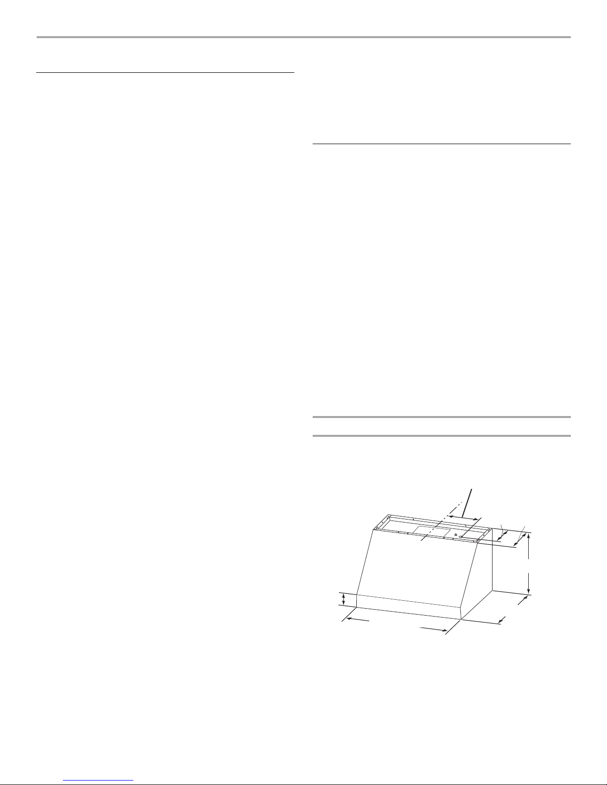
INSTALLATION REQUIREMENTS
†®TORX and T20 are registered trademarks of Acument Intellectual Properties, LLC
CL
18¹⁄₁₆" (45.9 cm) for 48" (121.9 cm) Hood
12¹⁄₁₆" (30.6 cm) for 36" (91.4 cm) Hood
9¹⁄₁₆" (23.0 cm) for 30" (76.2 cm) Hood
18" (45.7 cm)
12" (30.5 cm)
30" (76.2 cm)
36" (91.4 cm)
48" (121.9 cm)
2¹⁄₄"
(5.7 cm)
6¹⁄₂" (16.5 cm)
25" (63.5 cm)
Tools and Parts
Gather the required tools and parts before starting installation.
Read and follow the instructions provided with any tools listed
here.
Tools needed
■ Level
■ Drill
■ 1¼" (3 cm) drill bit
■ ¹⁄₈" (3 mm) drill bit if installing into wood and a ⁵⁄₁₆" (8 mm) drill
bit if installing optional backsplash kit.
■ Pencil
■ Wire stripper or utility knife
■ Tape measure or ruler
■ Pliers
■ Caulking gun and weatherproof caulking compound
■ Vent clamps
■ Jigsaw or keyhole saw
■ Flat-blade screwdriver
■ Metal snips
■ Phillips screwdriver
■ Scissors
Parts needed
■ Home power supply cable
■ 1 - ½" (12.7 mm) UL listed or CSA approved strain relief
■ 3 UL listed wire connectors
■ 1 wall or roof cap
■ Metal vent system
■ 5 - M6 x 16 mm screws
■ 5 - D6.4 x 11 mm washers
■ 2 - D5.3 x 20 mm washers
■ 2 - 10 x 50 mm wall anchors
■ T20
®
TORX®†adapter
Location Requirements
IMPORTANT: Observe all governing codes and ordinances.
Have a qualified technician install the range hood. It is the
installer's responsibility to comply with installation clearances
specified on the model/serial/rating plate. The model/serial/rating
plate is located inside the range hood on the rear wall of the
range hood.
Canopy range hood location should be away from strong draft
areas, such as windows, doors and strong heating vents.
Cabinet opening dimensions that are shown must be used. Given
dimensions provide minimum clearance.
The canopy range hood is factory set for venting through the roof
or through the wall.
All openings in ceiling and wall where canopy range hood will be
installed must be sealed.
For Mobile Home Installations
The installation of this range hood must conform to the
Manufactured Home Construction Safety Standards, Title 24
CFR, Part 328 (formerly the Federal Standard for Mobile Home
Construction and Safety, Title 24, HUD, Part 280) or when such
standard is not applicable, the standard for Manufactured Home
Installation 1982 (Manufactured Home Sites, Communities and
Setups) ANSI A225.1/NFPA 501A, or latest edition, or with local
codes.
Product Dimensions
Front view
Parts supplied
Remove parts from packages. Check that all parts are included.
■ 2 metal grease filters for 30" (76.2 cm) models
3 metal grease filters for 36" (91.4 cm) models
4 metal grease filters for 48" (121.9 cm) models
■ Damper
■ Hood canopy with blower and halogen lamps installed.
■ 1 - 10" (25.4 cm) square to 10" (25.4 cm) round duct
transition.
■ 2 - 175 watt infrared heat lamps
■ Wood support
■ Grease collectors
■ 4 - 6 x 80 mm mounting screws
■ 4 - 3.5 x 9.5 mm screws
■ 6 - 4.2 x 19 mm screws
5
Page 6
Back view
A
B
C
D
CL
E
18¹³⁄₁₆" (47.8 cm) for 48" (121.9 cm) Hood
12¹³⁄₁₆" (32.5 cm) for 36" (91.4 cm) Hood
9¹³⁄₁₆" (24.9 cm) for 30" (76.2 cm) Hood
18"
(45.7 cm)
8³⁄₈"
(21.3 cm)
9⁷⁄₈"
(25.0 cm)
12"
(30.5 cm)
18"
(45.7 cm)
12"
(30.5 cm)
A
B
13" (33.0 cm)
18" (45.7 cm)
min.
clearance upper
cabinet to countertop
36" (91.4 cm)
countertop height
30" (76.2 cm), 36" (91.4 cm),
or
48"
(121.9
cm)
cabinet opening width
(If installed between cabinets)
A B
Bottom of canopy
to cooking surface
Min. cabinet
opening width
Vent cover (if used)
Canopy
X
Installation Dimensions
A. Top of hood
B. Wood support
C. Bottom of hood
D. Home wiring system
E. Knockout into terminal box
Optional Full-Width Duct Cover Installations
A. Optional full-width duct cover
B. Range hood
A. 84" (213.4 cm) minimum for
installations with canopy only.
B. 96" (243.8 cm) minimum for
installations with optional
duct cover.
IMPORTANT:
Minimum distance “X”: 30" (76.2 cm)
Suggested maximum distance “X”: 36" (91.4 cm)
6
Page 7
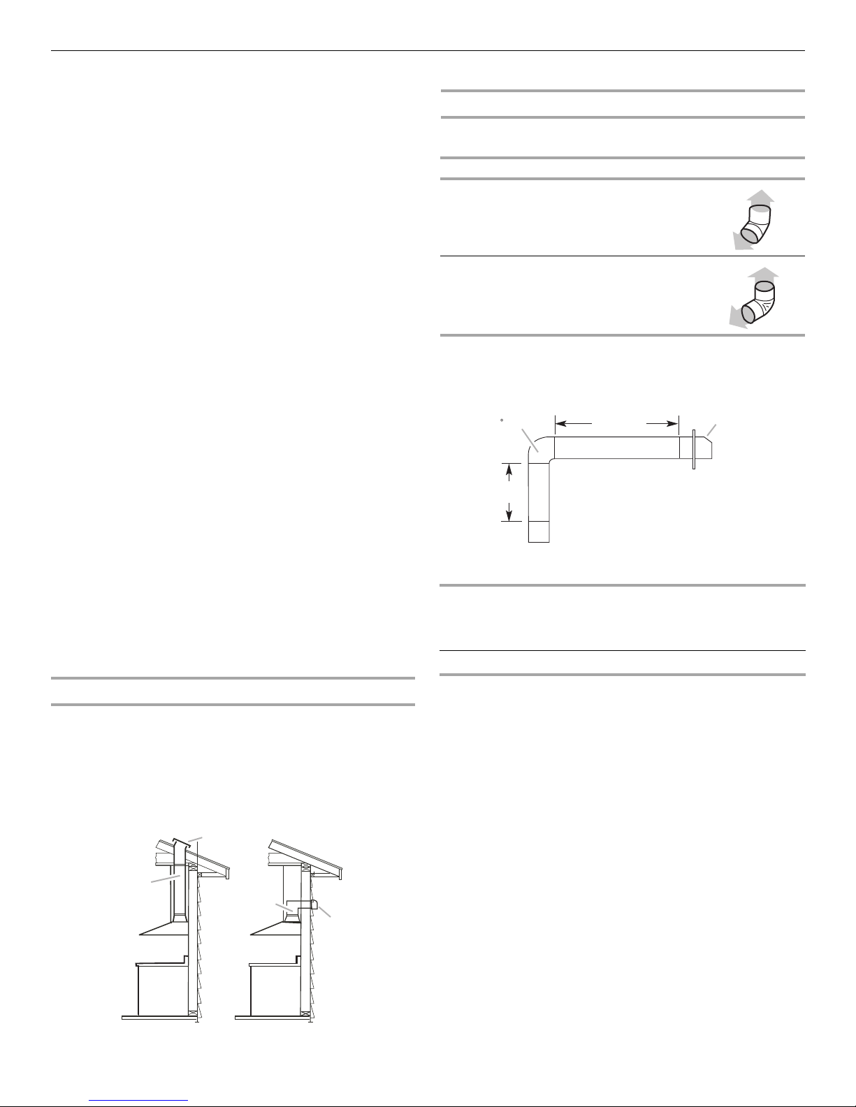
Venting Requirements
A
A
B*
B*
90 elbow
6 ft (1.8 m)
2 ft
(0.6 m)
Wall cap
■ Vent system must terminate to the outdoors.
■ Do not terminate the vent system in an attic or other enclosed
area.
■ Do not use 4" (10.2 cm) laundry-type wall caps.
■ Use metal vent only. Rigid metal vent is recommended.
Plastic or metal foil vent is not recommended.
■ The length of vent system and number of elbows should be
kept to a minimum to provide efficient performance.
For the most efficient and quiet operation:
■ Use no more than three 90° elbows.
■ Make sure there is a minimum of 24" (61.0 cm) of straight
vent between the elbows if more than 1 elbow is used.
■ Do not install 2 elbows together.
■ Use clamps to seal all joints in the vent system.
■ The vent system must have a damper. If the roof or wall cap
has a damper, do not use the damper supplied with the range
hood.
■ Use caulking to seal exterior wall or roof opening around the
cap.
■ The size of the vent should be uniform.
Cold weather installations
An additional back draft damper should be installed to minimize
backward cold air flow and a thermal break should be installed to
minimize conduction of outside temperatures as part of the vent
system. The damper should be on the cold air side of the thermal
break.
The break should be as close as possible to where the vent
system enters the heated portion of the house.
Makeup air
Local building codes may require the use of makeup air systems
when using ventilation systems greater than specified CFM of air
movement. The specified CFM varies from locale to locale.
Consult your HVAC professional for specific requirements in your
area.
Calculating Vent System Length
To calculate the length of the system you need, add the
equivalent feet (meters) for each vent piece used in the system.
Vent Piece Equivalent Length
45° elbow 2.5 ft
(0.8 m)
90° elbow 5.0 ft
(1.5 m)
The maximum equivalent vent lengths are:
10" (25.4 cm) round vents - 60 ft (18.3 m)
Example vent system
The following example falls within the maximum recommended
vent length.
1 - 90° elbow = 5.0 ft (1.5 m)
1 - wall cap = 0.0 ft (0.0 m)
8 ft (2.4 m) straight = 8.0 ft (2.4 m)
Length of system = 13.0 ft (3.9 m)
Venting Methods
A 10" (25.4 cm) round vent system is needed for installation (not
included). The hood exhaust opening is 10" (25.4 cm) round.
NOTE: Flexible vent is not recommended. Flexible vent creates
back pressure and air turbulence that greatly reduce
performance.
Vent system can terminate either through the roof or wall.
Roof Venting Wall Venting
A. Roof cap
B. 10" (25.4 cm) round vent
A. Wall cap
B. 10" (25.4 cm) round vent
7
Page 8
Electrical Requirements
WARNING
Excessive Weight Hazard
Use two or more people to move and install
range hood.
Failure to do so can result in back or other injury.
A
B
30" (76.2 cm)
to 36" (91.4 cm)
15³⁄₈"
(39 cm)
Observe all governing codes and ordinances.
Ensure that the electrical installation is adequate and in
conformance with National Electrical Code, ANSI/NFPA 70 (latest
edition), or CSA Standards C22.1-94, Canadian Electrical Code,
Part 1 and C22.2 No. 0-M91 (latest edition) and all local codes
and ordinances.
If codes permit and a separate ground wire is used, it is
recommended that a qualified electrician determine that the
ground path is adequate.
A copy of the above code standards can be obtained from:
National Fire Protection Association
1 Batterymarch Park
Quincy, MA 02169-7471
CSA International
8501 East Pleasant Valley Road
Cleveland, OH 44131-5575
■ A 120 volt, 60 Hz., AC only, 15-amp, fused electrical circuit is
required.
INSTALLATION INSTRUCTIONS
Prepare Location
■ It is recommended that the vent system be installed before
hood is installed.
■ If you are installing the optional backsplash with shelves for
heat lamps, follow the instructions included with that product.
■ Before making cutouts, make sure there is proper clearance
within the ceiling or wall for exhaust vent.
■ Check that all installation parts have been removed from the
shipping carton.
1. Disconnect power.
2. Determine which venting method to use: roof or wall exhaust.
3. Select a flat surface for assembling the range hood. Place
covering over that surface.
■ If the house has aluminum wiring, follow the procedure
below:
1. Connect a section of solid copper wire to the pigtail
leads.
2. Connect the aluminum wiring to the added section
of copper wire using special connectors and/or tools
designed and UL listed for joining copper to aluminum.
Follow the electrical connector manufacturer's recommended
procedure. Aluminum/copper connection must conform with
local codes and industry accepted wiring practices.
■ Wire sizes and connections must conform with the rating of
the appliance as specified on the model/serial/rating plate.
The model/serial/rating plate is located behind the left filter
on the rear wall of the range hood.
■ Wire sizes must conform to the requirements of the National
Electrical Code, ANSI/NFPA 70 (latest edition), or CSA
Standards C22. 1-94, Canadian Electrical Code, Part 1
and C22.2 No. 0-M91 (latest edition) and all local codes
and ordinances.
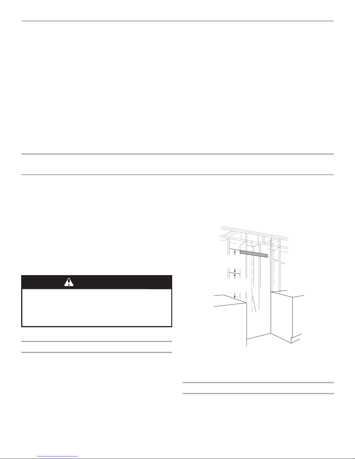
3. Remove the wood support from the back of the range hood
by loosening the 2 screws from the inside. Locate and level
the top of the wood support 15³⁄₈" (39.1 cm) above the
marked horizontal line and centered on the vertical centerline.
Using 2 - 4 of the 6 x 80 mm screws, install wood support so
that it is screwed into at least 2 vertical studs.
4. Using 2 or more people, lift range hood onto covered surface.
Range Hood Mounting Screws Installation
The hood is attached to the wall with the wood support that is
attached to the back of the hood.
1. Determine and mark the centerline on the wall where the
canopy range hood will be installed.
2. Select a mounting height between a minimum of 30"
(76.2 cm) and a suggested maximum of 36" (91.4 cm)
above the cooking surface and the bottom of the range
hood, and mark a horizontal reference line on the wall.
8
A. Wood support
B. Centerline
NOTE: The screws provided for mounting this hood must be
fastened into solid wood. Do not fasten into sheet rock only.
Optional Duct Cover Installation
1. Attach the full-width duct cover to the top of the range hood
with the screws provided with duct covers. The duct cover
must be attached to the top of the range hood before
mounting the range hood to the wall. For information on
ordering the optional duct cover, see the “Accessories”
section.
Page 9

Complete Preparation
→
→
→
→
A
A
B
A
1. Determine and make all necessary cuts in the wall for the vent
system. Install the vent system before installing the range
hood. See the “Venting Requirements” section.
2. Determine the location where the power supply cable will be
run through the wall.
3. Drill a 1¹⁄₄" (3.2 cm) hole at this location.
4. Pull enough power supply cable through the wall to allow for
easy connection to the terminal box.
5. Install the 10" (25.4 cm) square x 10" (25.4 cm) round vent
transition with damper to top of the range hood using 4 - 3.5
x 9.5 mm screws.
6. Remove terminal box cover and set aside.
7. Remove knockout from the back of the vent hood and install
a UL listed or CSA approved ¹⁄₂" strain relief. See “Make
Electrical Connection” section.
8. Place the range hood near its mounting position and run the
power supply cable through the strain relief into terminal box
(enough to make connection).
9. Tighten the strain relief screws.
Install Range Hood
The hood attaches to the wall by the 2 mounting screws in the
wood support mounted to the wall in “Range Hood Mounting
Screws Installation” in the “Prepare Location” section.
1. Using 2 or more people, hang the range hood on the wall by
placing the slotted holes in the range hood back over the
2 screws mounted to the wood support mounted to the wall.
NOTE: If your installation uses the optional duct cover, the
vent system needs to be connected to the hood and the duct
cover mounted to the top of the range hood before tightening
the mounting screws. See steps 5 and 6.
Install Range Hood Blower Motor
1. Install the range hood blower motor assembly inside the hood
canopy with the wiring to the left.
A. Blower motor
2. Slide the left mounting plate flange under the bracket.
A. Bracket
B. Mounting plate flange
3. Push the right end of the mounting plate up and snap into
spring tab.
NOTE: The spring tab should be outside of the slot in the
mounting plate.
2. Push the range hood up into the narrow slots, align the
bottom of the hood to the horizontal line, level the hood,
and tighten the 2 mounting screws.
3. Mark 2 lower mounting hole locations. Drill ¹⁄₈" pilot holes if
the holes are located in wood. If holes are not located in
wood, remove the hood and drill two ³⁄₈" pilot holes and insert
10 x 50 mm wall anchors. Remount the hood, level, and
tighten the upper screws. Install 2 - 6 x 80 mm screws into
the lower mounting anchors and tighten.
4. Install 4 - 4.2 x 19 mm screws through the back of the hood
into the wood support and tighten.
5. Connect vent system to hood. Seal all joints with clamps.
6. If your installation uses the optional duct cover, mount it to
the top of the range hood following the instructions supplied
with the duct cover.
A. Spring tab
9
Page 10
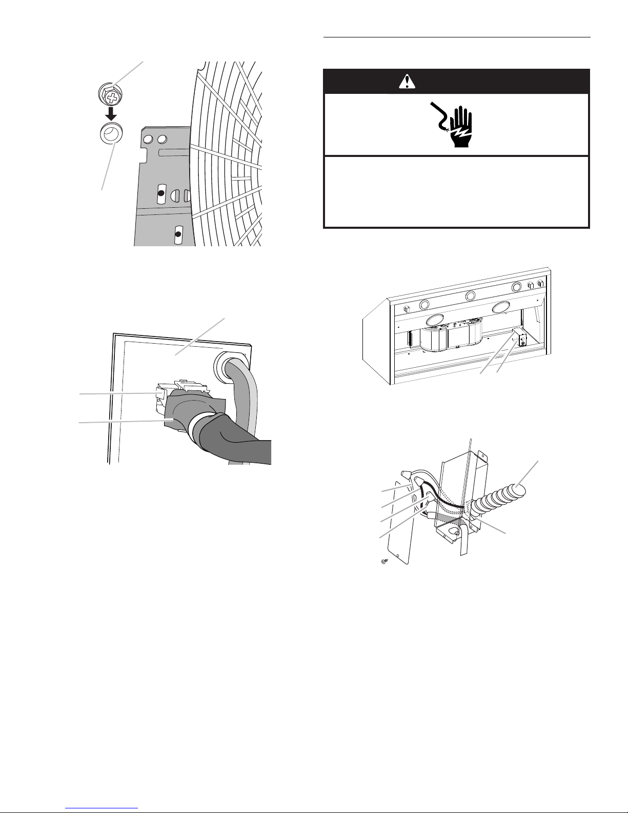
4. Align mounting holes and install 5 - 6 x 16 mm screws.
A
B
B
C
A
WARNING
Electrical Shock Hazard
Disconnect power before servicing.
Replace all parts and panels before operating.
Failure to do so can result in death or electrical shock.
A
B
A
B
C
D
E
F
A. Screw
B. Mounting hole
5. Attach power cord connector to connector on wire box on
blower motor mounting plate.
Make Electrical Connection
1. Disconnect power.
2. Locate junction box inside of the range hood.
A. Blower motor mounting plate
B. Wire box connector
C. Power cord
A. Terminal box cover
B. Knockout in canopy back into terminal box
A. White wires
B. Black wires
C. UL listed wire connectors
D. Green, bare or yellow/green wires
E. Home power supply
F. UL listed or CSA approved
¹⁄₂
" strain relief
10
Page 11

3. Use UL listed wire connectors and connect black wires (B)
WARNING
Electrical Shock Hazard
Electrically ground blower.
Connect ground wire to green and yellow ground wire
in terminal box.
Failure to do so can result in death or electrical shock.
A
B
C
D
E
F
G
together.
4. Use UL listed wire connectors and connect white wires (A)
together.
5. Connect green (or bare) ground wire from home power supply
to the green/yellow ground wire (D) in terminal box using UL
listed wire connectors.
6. Install terminal box cover.
7. Check that all light bulbs are secure in their sockets.
8. Reconnect power.
Complete Installation and Check
Operation
1. Install grease filters. See the “Range Hood Care” section.
2. Install heat lamps into heat lamp sockets.
3. Check operation of the range hood blower and lights. See the
“Range Hood Use” section.
A. Infrared lamp
B. Grease filter handles
C. Grease filter
D. Blower control switch
E. Halogen light switch
F. Halogen lights
G. Infrared lamp controls
4. If range hood does not operate, check to see whether a circuit
breaker has tripped or a household fuse has blown.
Disconnect power supply and check that the wiring is correct.
NOTE: To get the most efficient use from your new range hood,
read the “Range Hood Use” section.
11
Page 12

RANGE HOOD USE
A
B
C
WARNING
Food Poisoning Hazard
Do not let food sit for more than one hour before or
after cooking.
Doing so can result in food poisoning or sickness.
The range hood is designed to remove smoke, cooking vapors
and odors from the cooktop area. For best results, start the hood
before cooking and allow it to operate several minutes after the
cooking is complete to clear all smoke and odors from the
kitchen.
The hood controls are located on the right-hand underside of the
range hood.
A. Infrared lamp switch
B. Halogen light switch
C. Blower control switch
Range Hood Controls
Operating the lights
1. Turn the light switch to the Night position to use the range
hood lights as a night light.
2. Turn the light switch to the High position to turn the range
hood lights On.
3. Turn the light switch to the Off position to turn the range hood
lights Off.
Operating the blower
1. Turn the blower switch to the first position to turn the range
hood on Low.
2. Turn the blower switch to the second position to turn the
range hood on Medium.
3. Turn the blower switch to the third position to turn the range
hood on Medium - High.
4. Turn the blower switch to the High position to turn the range
hood on High.
5. Turn the blower switch to the Off position to turn the range
hood blower Off.
Operating the heat lamp
NOTE: Heat lamp bulbs should be rated to a maximum of
175 watts each.
1. Turn the heat lamp switch to the High position to turn the heat
lamps On.
2. Turn the heat lamp switch to the Off position to turn the heat
lamps Off.
12
Page 13

RANGE HOOD CARE
A
A
A
Range Hood Lamps
4. Repeat steps 2 and 3 for the other lamp if needed.
5. Reconnect power.
Replacing a Halogen Lamp
Turn off the range hood and allow the halogen lamp to cool. To
avoid damage or decreasing the life of the new bulb, do not
touch bulb with bare fingers. Replace bulb, using tissue or
wearing cotton gloves to handle bulb.
If new lamps do not operate, make sure the lamps are inserted
correctly before calling service.
1. Disconnect power.
2. Push up on the lens and turn it counterclockwise.
3. Remove the bulb and replace it with a 120-volt, 50-watt
maximum halogen bulb with a GU10 base. Turn it clockwise
to lock it into place.
4. Repeat steps 2 and 3 for the other bulb if needed.
5. Reconnect power.
Cleaning
Exterior surfaces:
To avoid damage to the exterior surface, do not use steel wool
or soap-filled scouring pads. Rub in direction of the grain line to
avoid scratching the surface.
Always wipe dry to avoid water marks.
■ Stainless Steel Cleaner and Polish.
■ Mild liquid detergent and water.
■ Wipe with damp soft cloth or nonabrasive sponge, then rinse
with clean water and wipe dry.
Metal Filters and Drip Trays:
Use 2 hands to remove filters. Grasp filter handles, pull toward
the front of range hood and pull down on the rear handle to
remove. Repeat for each filter.
A. Grease filter
Remove grease drip tray.
Replacing the Infrared Heat Lamps
Turn off the range hood and allow the infrared heat lamp to cool.
To avoid damage or decreasing the life of the new lamp, do not
touch lamp with bare fingers. Replace lamp, using tissue or
wearing cotton gloves to handle lamp.
If new lamps do not operate, make sure the lamps are inserted
correctly before calling service.
1. Disconnect power.
2. Twist lamp counterclockwise to remove.
3. Remove the lamp and replace it with a 120-volt, 175-watt
maximum, PAR38 IR lamp made for E-26 base. Twist lamp
clockwise to screw it into place.
A. Drip tray
Wash metal filters and grease trays as needed in dishwasher or
hot detergent solution to clean.
Replace grease drip tray.
Reinstall filters, grasp filter handles and place front edge of filter
into the hood. Push up on the back handle and set rear of filter
into the drip tray to secure. Repeat for each filter.
A. Grease filter
Thermal Protector
The range hood is equipped with a thermal protector to avoid
overheating conditions. If the range hood shuts off while in use,
move the blower switch to the Off position. Wait approximately
60 minutes, then move the blower switch to the first position to
restart the range hood.
13
Page 14

WIRING DIAGRAM
NL
Gnd
BK
WH
YL/GN
WH
BK
MOTOR SPECIFICATIONS
Power Supply 120 VAC
Frequency 60 Hz
Power Absorption 240 Watts
Current
MOTOR RESISTANCE (Ohms)
Blue - Black 9.8
Blue - Gray 14.3
Blue - Red 18
Blue - White
Room Temp. 73.4°F (23°C)
BK
a
Motor
BU
e
SE12ZA
1
2
3
Switch
4
5
3.7 A
21.6
WH
BK
WH
YL/GN
WH
RD
GY
BK
BU
BK
BK
WH
2
1
BU
BK
b
Switch
IR Lamp
a
LAMP SWITCH
a-1
Low Light
a-2
High Light
Neutral
c-3
IR LAMP SWITCH
On
a-1
Neutral
b-2
MOTOR SWITCH
1st Speed
a-1
2nd Speed
a-2
a-3
3rd Speed
a-4
4th Speed
e-5
Neutral
YL/GN
6
WH
5
4
3
2
1
RD
GY
BK
BU
YL
BR
YL
BR
YL/GN
9
8
6
5
4
37
2
1
3rd Halogen Lamp
in 48" (121.9 cm)
WH
BK
L
N
GY
WH
3
c
a
YL/GN
Lamp
Switch
WH
RD
2
1
GY
BK
BU
BK
YL/GN
WH
RD
GY
BK
BU
YL
BR
YL
BR
WH
N
WH
GY
GY
WH
N
L
2nd Motor in
48" (121.9 cm)
M
BK
BK
L
WH
S50
M
S50
14
Page 15

ASSISTANCE OR SERVICE
If you need service
Please refer to the warranty page in this manual.
If you need replacement parts
If you need to order replacement parts, we recommend that you
use only factory specified parts. Factory specified parts will fit
right and work right because they are made with the same
precision used to build every new appliance.
To locate factory specified replacement parts in your area, call
the following customer assistance telephone number or your
nearest designated service center.
In the U.S.A.
Call Jenn-Air Customer eXperience Center toll free:
1-800-JENNAIR (1-800-536-6247) or visit our website at
www.jennair.com.
Our consultants provide assistance with:
■ Scheduling of service. Jenn-Air
service technicians are trained to fulfill the product warranty
and provide after-warranty service anywhere in the United
States.
■ Features and specifications on our full line of appliances.
■ Referrals to local Jenn-Air
■ Installation information.
■ Use and maintenance procedures.
■ Accessory and repair parts sales.
■ Specialized customer assistance (Spanish speaking, hearing
impaired, limited vision, etc.).
For further assistance
If you need further assistance, you can write to Jenn-Air®
Appliances with any questions or concerns at:
Jenn-Air Brand Home Appliances
Customer eXperience Center
553 Benson Road
Benton Harbor, MI 49022-2692
Please include a daytime phone number in your correspondence.
®
appliances designated
®
appliance dealers.
In Canada
Call the Whirlpool Canada LP Customer eXperience Centre toll
free at 1-800-JENNAIR (1-800-536-6247) or visit our website at
www.jennair.ca.
Our consultants provide assistance with:
■ Scheduling of service. Jenn-Air
®
appliances designated
service technicians are trained to fulfill the product warranty
and provide after-warranty service anywhere in Canada.
■ Features and specifications on our full line of appliances.
■ Referrals to local Jenn-Air
■ Installation information.
■ Use and maintenance procedures.
■ Accessory and repair parts sales.
®
appliance dealers.
For further assistance
If you need further assistance, you can write to Jenn-Air®
Appliances with any questions or concerns at:
Jenn-Air Brand Home Appliances
Customer eXperience Centre
200 - 6750 Century Ave.
Mississauga, Ontario L5N 0B7
Please include a daytime phone number in your correspondence.
Accessories
Full-Width Duct Cover
Order Part Number W10272079 for 30" (76.2 cm) model
Order Part Number W10272080 for 36" (91.4 cm) model
Order Part Number W10272081 for 48" (121.9 cm) model
Backsplash Kit (with shelves)
Order Part Number W10285447 for 30" (76.2 cm) model
Order Part Number W10285448 for 36" (91.4 cm) model
Order Part Number W10285449 for 48" (121.9 cm) model
15
Page 16

ATTACH YOUR RECEIPT HERE. PROOF OF PURCHASE IS REQUIRED
https://jennair.custhelp.com
JENN-AIR®
MAJOR APPLIANCE
LIMITED WARRANTY
TO OBTAIN WARRANTY SERVICE.
Please have the following information available when you call the
Customer eXperience Center:
■ Name, address and telephone number
■ Model number and serial number
■ A clear, detailed description of the problem
■ Proof of purchase including dealer or retailer name and address
IF YOU NEED SERVICE:
1. Before contacting us to arrange service, please determine whether your product requires repair. Some
questions can be addressed without service. Please take a few minutes to review the Troubleshooting or
Problem Solver section of the Use and Care Guide, scan the QR code on the right to access additional
resources, or visit https://jennair.custhelp.com.
2. All warranty service is provided exclusively by our authorized Jenn-Air Service Providers
Canada, direct all requests for warranty service to:
Jenn-Air Customer eXperience Center
1-800-JENNAIR (1-800-536-6247)
If outside the 50 United States or Canada, contact your authorized Jenn-Air dealer to determine whether another warranty applies.
TWO YEAR LIMITED WARRANTY
WHAT IS COVERED WHAT IS NOT COVERED
For two years from the date of purchase, when this
major appliance is installed, operated and maintained
according to instructions attached to or furnished with
the product, Jenn-Air brand of Whirlpool Corporation or
Whirlpool Canada LP (hereafter “Jenn-Air”) will pay for
Factory Specified Replacement Parts and repair labor
to correct defects in materials or workmanship that
existed when this major appliance was purchased, or at
its sole discretion replace the product. In the event of
product replacement, your appliance will be warranted
for the remaining term of the original unit's warranty
period.
YOUR SOLE AND EXCLUSIVE REMEDY UNDER THIS
LIMITED WARRANTY SHALL BE PRODUCT REPAIR
AS PROVIDED HEREIN. Service must be provided by a
Jenn-Air designated service company. This limited
warranty is valid only in the United States or Canada
and applies only when the major appliance is used in
the country in which it was purchased. This limited
warranty is effective from the date of original consumer
purchase. Proof of original purchase date is required to
obtain service under this limited warranty.
1. Commercial, non-residential, multiple-family use, or use inconsistent with published
user, operator or installation instructions.
2. In-home instruction on how to use your product.
3. Service to correct improper product maintenance or installation, installation not in
accordance with electrical or plumbing codes or correction of household electrical or
plumbing (i.e. house wiring, fuses or water inlet hoses).
4. Consumable parts (i.e. light bulbs, batteries, air or water filters, preservation
solutions, etc.).
5. Defects or damage caused by the use of non-genuine Jenn-Air parts or accessories.
6. Conversion of products from natural gas or L.P. gas.
7. Damage from accident, misuse, abuse, fire, floods, acts of God or use with products
not approved by Jenn-Air.
8. Repairs to parts or systems to correct product damage or defects caused by
unauthorized service, alteration or modification of the appliance.
9. Cosmetic damage including scratches, dents, chips, and other damage to the
appliance finishes unless such damage results from defects in materials and
workmanship and is reported to Jenn-Air within 30 days.
10. Discoloration, rust or oxidation of surfaces resulting from caustic or corrosive
environments including but not limited to high salt concentrations, high moisture or
humidity or exposure to chemicals.
11. Food or medicine loss due to product failure.
12. Pick-up or delivery. This product is intended for in-home repair.
13. Travel or transportation expenses for service in remote locations where an authorized
Jenn-Air servicer is not available.
14. Removal or reinstallation of inaccessible appliances or built-in fixtures (i.e. trim,
decorative panels, flooring, cabinetry, islands, countertops, drywall, etc.) that
interfere with servicing, removal or replacement of the product.
15. Service or parts for appliances with original model/serial numbers removed, altered
or not easily determined.
The cost of repair or replacement under these excluded circumstances shall be
borne by the customer.
. In the U.S. and
DISCLAIMER OF IMPLIED WARRANTIES
IMPLIED WARRANTIES, INCLUDING ANY IMPLIED WARRANTY OF MERCHANTABILITY OR IMPLIED WARRANTY OF FITNESS FOR A
PARTICULAR PURPOSE, ARE LIMITED TO ONE YEAR OR THE SHORTEST PERIOD ALLOWED BY LAW. Some states and provinces do not allow
limitations on the duration of implied warranties of merchantability or fitness, so this limitation may not apply to you. This warranty gives you
specific legal rights, and you also may have other rights that vary from state to state or province to province.
DISCLAIMER OF REPRESENTATIONS OUTSIDE OF WARRANTY
Jenn-Air makes no representations about the quality, durability, or need for service or repair of this major appliance other than the representations
contained in this warranty. If you want a longer or more comprehensive warranty than the limited warranty that comes with this major appliance,
you should ask Jenn-Air or your retailer about buying an extended warranty.
LIMITATION OF REMEDIES; EXCLUSION OF INCIDENTAL AND CONSEQUENTIAL DAMAGES
YOUR SOLE AND EXCLUSIVE REMEDY UNDER THIS LIMITED WARRANTY SHALL BE PRODUCT REPAIR AS PROVIDED HEREIN. JENN-AIR
SHALL NOT BE LIABLE FOR INCIDENTAL OR CONSEQUENTIAL DAMAGES. Some states and provinces do not allow the exclusion or limitation
of incidental or consequential damages, so these limitations and exclusions may not apply to you. This warranty gives you specific legal rights, and
you also may have other rights that vary from state to state or province to province.
16
12/14
Page 17

SÉCURITÉ DE LA HOTTE DE CUISINIÈRE
Risque possible de décès ou de blessure grave si vous ne
suivez pas immédiatement les instructions.
Risque possible de décès ou de blessure grave si vous
ne suivez pas les instructions.
Tous les messages de sécurité vous diront quel est le danger potentiel et vous disent comment réduire le risque de blessure et
ce qui peut se produire en cas de non-respect des instructions.
Votre sécurité et celle des autres est très importante.
Nous donnons de nombreux messages de sécurité importants dans ce manuel et sur votre appareil ménager. Assurez-vous de
toujours lire tous les messages de sécurité et de vous y conformer.
AVERTISSEMENT
DANGER
Voici le symbole d’alerte de sécurité.
Ce symbole d’alerte de sécurité vous signale les dangers potentiels de décès et de blessures graves à vous
et à d’autres.
Tous les messages de sécurité suivront le symbole d’alerte de sécurité et le mot “DANGER” ou
“AVERTISSEMENT”. Ces mots signifient :
Avertissements de la proposition 65 de l'État de Californie :
AVERTISSEMENT : Ce produit contient au moins un produit chimique connu par l’État de Californie pour être à l’origine de
cancers.
AVERTISSEMENT : Ce produit contient au moins un produit chimique connu par l’État de Californie pour être à l’origine de
malformations et autres déficiences de naissance.
17
Page 18

IMPORTANTES INSTRUCTIONS DE SÉCURITÉ
LIRE ET CONSERVER CES INSTRUCTIONS
AVERTISSEMENT : POUR RÉDUIRE LE RISQUE
D'INCENDIE, CHOC ÉLECTRIQUE OU DOMMAGES
CORPORELS, RESPECTER LES INSTRUCTIONS
SUIVANTES :
■ Utiliser cet appareil uniquement dans les applications
envisagées par le fabricant. Pour toute question, contacter
le fabricant.
■ Avant d'entreprendre un travail d'entretien ou de nettoyage,
interrompre l'alimentation de la hotte au niveau du tableau
de disjoncteurs, et verrouiller le tableau de disjoncteurs
pour empêcher tout rétablissement accidentel de
l'alimentation du circuit. Lorsqu'il n'est pas possible de
verrouiller le tableau de disjoncteurs, placer sur le tableau
de disjoncteurs une étiquette d'avertissement proéminente
interdisant le rétablissement de l'alimentation.
■ Tout travail d'installation ou câblage électrique doit être
réalisé par une personne qualifiée, dans le respect des
prescriptions de tous les codes et normes applicables, y
compris les codes du bâtiment et de protection contre les
incendies.
■ Ne pas faire fonctionner un ventilateur dont le cordon ou la
fiche est endommagé(e). Jeter le ventilateur ou le retourner
à un centre de service agréé pour examen et/ou réparation.
■ Une source d'air de débit suffisant est nécessaire pour le
fonctionnement correct de tout appareil à gaz (combustion
et évacuation des gaz à combustion par la cheminée), pour
qu'il n'y ait pas de reflux des gaz de combustion. Respecter
les directives du fabricant de l'équipement de chauffage et
les prescriptions des normes de sécurité - comme celles
publiées par la National Fire Protection Association (NFPA)
et l'American Society for Heating, Refrigeration and Air
Conditioning Engineers (ASHRAE), et les prescriptions des
autorités réglementaires locales.
■ Lors des opérations de découpage et de perçage dans un
mur ou un plafond, ne pas endommager les câblages
électriques et les canalisations qui peuvent s’y trouver.
■ Les ventilateurs d'évacuation doivent toujours décharger
l'air à l'extérieur.
MISE EN GARDE : Cet appareil est conçu uniquement
pour la ventilation générale. Ne pas l'utiliser pour l'extraction
de matières ou vapeurs dangereuses ou explosives.
MISE EN GARDE : Pour minimiser le risque d'incendie
et évacuer adéquatement les gaz, veiller à acheminer l'air
aspiré par un conduit jusqu'à l'extérieur - ne pas décharger
l'air aspiré dans un espace vide du bâtiment comme une
cavité murale, un plafond, un grenier, un vide sanitaire ou
un garage.
AVERTISSEMENT : POUR RÉDUIRE LE RISQUE
D'INCENDIE, UTILISER UNIQUEMENT DES CONDUITS
MÉTALLIQUES.
AVERTISSEMENT : POUR MINIMISER LE RISQUE
D'UN FEU DE GRAISSE SUR LA CUISINIÈRE :
■ Ne jamais laisser un élément de surface fonctionner à
puissance de chauffage maximale sans surveillance. Un
renversement/débordement de matière graisseuse pourrait
provoquer une inflammation et la génération de fumée.
Utiliser une puissance de chauffage moyenne ou basse
pour le chauffage d'huile.
■ Veiller à toujours faire fonctionner le ventilateur de la hotte
lors de la cuisson avec une puissance de chauffage élevée
ou lors de la cuisson d'un mets à flamber (à savoir crêpes
Suzette, cerise jubilée, steak au poivre flambé).
■ Nettoyer fréquemment les ventilateurs d'extraction. Veiller à
ne pas laisser la graisse s'accumuler sur les surfaces du
ventilateur ou des filtres.
■ Utiliser toujours un ustensile de taille appropriée. Utiliser
toujours un ustensile adapté à la taille de l'élément
chauffant.
AVERTISSEMENT : POUR RÉDUIRE LE RISQUE DE
DOMMAGES CORPORELS APRÈS LE DÉCLENCHEMENT
D'UN FEU DE GRAISSE SUR LA CUISINIÈRE, APPLIQUER
LES RECOMMANDATIONS SUIVANTES :
a
■ Placer sur le récipient un couvercle bien ajusté, une tôle à
biscuits ou un plateau métallique POUR ÉTOUFFER LES
FLAMMES, puis éteindre le brûleur. VEILLER À ÉVITER
LES BRÛLURES. Si les flammes ne s'éteignent pas
immédiatement, ÉVACUER LA PIÈCE ET APPELER LES
POMPIERS.
■ NE JAMAIS PRENDRE EN MAIN UN RÉCIPIENT
ENFLAMMÉ - vous risquez de vous brûler.
■ NE PAS UTILISER D'EAU, ni un torchon humide - ceci
pourrait provoquer une explosion de vapeur brûlante.
■ Utiliser un extincteur SEULEMENT si :
– Il s'agit d'un extincteur de classe ABC, dont on connaît le
fonctionnement.
– Il s'agit d'un petit feu encore limité à l'endroit où il s'est
déclaré.
– Les pompiers ont été contactés.
– Il est possible de garder le dos orienté vers une sortie
pendant l'opération de lutte contre le feu.
a
Recommandations tirées des conseils de sécurité en cas
d'incendie de cuisine publiés par la NFPA.
■ AVERTISSEMENT : Pour réduire le risque d'incendie
ou de choc électrique, ne pas utiliser ce ventilateur avec un
quelconque dispositif de réglage de la vitesse à semiconducteurs.
18
Page 19

EXIGENCES D'INSTALLATION
†®TORX et T20 sont des marques déposées de Acument Intellectual Properties, LLC.
CL
18¹⁄₁₆" (45,9 cm) pour hotte de 48" (121,9 cm)
12¹⁄₁₆" (30,6 cm) pour hotte 36" (91,4 cm)
9¹⁄₁₆" (23,0 cm) pour hotte 30" (76,2 cm)
18" (45,7 cm)
12" (30,5 cm)
30" (76,2 cm)
36" (91,4 cm)
48" (121,9 cm)
2¹⁄₄"
(5,7 cm)
6¹⁄₂" (16,5 cm)
25" (63,5 cm)
Outillage et pièces
Rassembler les outils et pièces nécessaires avant de commencer
l'installation. Lire et suivre les instructions fournies avec les outils
indiqués ici.
Outils nécessaires
■ Niveau
■ Perceuse
■ Foret de 1¼" (3 cm)
■ Foret de ¹⁄₈" (3 mm) en cas d'installation dans du bois et foret
de ⁵⁄₁₆" (8 mm) en cas d'installation de l'ensemble de dosseret
facultatif.
■ Crayon
■ Pince à dénuder ou couteau utilitaire
■ Mètre-ruban ou règle
■ Pince
■ Pistolet à calfeutrage et composé de calfeutrage résistant
aux intempéries
■ Brides de serrage pour conduit d'évacuation
■ Scie sauteuse ou scie à guichet
■ Tournevis à lame plate
■ Cisaille de ferblantier
■ Tournevis Phillips
■ Ciseaux
Pièces nécessaires
■ Câble d'alimentation électrique du domicile
■ 1 serre-câble de ½" (12,7 mm) (homologation UL ou CSA)
■ 2 connecteurs de fils homologués UL
■ 1 bouche de décharge (décharge à travers le mur ou à travers
le toit)
■ Conduit d'évacuation métallique
■ 2 joints de D5,3 x 20 mm
■ 2 chevilles d’ancrage de 10 x 50 mm
®†
■ Adaptateur TORX
T20
®
Exigences d'emplacement
IMPORTANT : Observer les dispositions de tous les codes et
règlements en vigueur.
Confier l'installation de la hotte à un technicien qualifié. C'est à
l'installateur qu'incombe la responsabilité de respecter les
distances de séparation spécifiées sur la plaque signalétique de
l'appareil. La plaque signalétique est située à l’intérieur de la
hotte, sur la paroi arrière.
On doit toujours installer la hotte à distance des sources de
courant d’air (fenêtres, portes et évents de chauffage puissants).
Respecter les dimensions indiquées pour les ouvertures à
découper dans les placards. Ces dimensions tiennent compte
des valeurs minimales des dégagements de séparation.
Cette hotte a été configurée à l’usine pour une décharge à travers
le toit ou à travers le mur.
Assurer l'étanchéité au niveau de chaque ouverture découpée
dans le plafond ou le mur pour l'installation de la hotte de
cuisinière.
Installation dans une résidence mobile
L’installation de cette hotte doit satisfaire aux exigences de la
norme Manufactured Home Construction Safety Standards, Titre
24 CFR, partie 328 (anciennement Federal Standard for Mobile
Home Construction and Safety, titre 24, HUD, partie 280); lorsque
cette norme n’est pas applicable, l’installation doit satisfaire aux
critères de la plus récente édition de la norme Manufactured
Home Installation 1982 (Manufactured Home Sites, Communities
and Setups) ANSI A225.1/NFPA 501A, ou des codes et
règlements locaux.
Dimensions du produit
Vue avant
Pièces fournies
Retirer les pièces des emballages. Vérifier que toutes les pièces
sont présentes.
■ 2 filtres à graisse métalliques, pour modèle de 30" (76,2 cm)
3 filtres à graisse métalliques, pour modèle de 36" (91,4 cm)
4 filtres à graisse métalliques, pour modèle de 48" (121,9 cm)
■ Clapet
■ Auvent de hotte avec ventilateur et lampes à halogène.
■ 1 raccord de conduit carré de 10" (25,4 cm) à conduit rond de
10" (25,4 cm).
■ 2 lampes à rayons infrarouges de 175 watts.
■ Support en bois
■ Collecteurs de graisse
■ 4 vis de montage de 6 x 80 mm
■ 4 vis de 3,5 x 9,5 mm
■ 6 vis de 4,2 x 19 mm
■ 5 vis de M6 x 16 mm
■ 5 joints de D6,4 x 11 mm
19
Page 20

Vue arrière
A
B
C
D
CL
E
18¹³⁄₁₆" (47,8 cm) pour hotte de 48" (121,9 cm)
12¹³⁄₁₆" (32,5 cm)
pour hotte de 36" (91,4 cm)
9¹³⁄₁₆" (24,9 cm)
pour hotte de 30" (76,2 cm)
18"
(45,7 cm)
8³⁄₈"
(21,3 cm)
9⁷⁄₈"
(25,0 cm)
12"
(30,5 cm)
18"
(45,7 cm)
12"
(30,5 cm)
A
B
13" (33,0 cm)
18" (45,7 cm)
de dégagement minimum
entre le placard supérieur
et le plan de travail
36" (91,4 cm)
de hauteur jusqu'au
plan de travail
30" (76,2 cm), 36" (91,4 cm),
ou
48"
(121,9
cm)
cavité d'encastrement
(en cas d'installation entre des placards)
A B
Du bas de la hotte
à la surface de cuisson
Cavité d'encastrement
minimum
Couvercle de l'évent
(le cas échéant)
Hotte
X
Dimensions d’installation
A. Haut de la hotte
B. Support en bois
C. Bas de la hotte
D. Emplacement du câblage
de la maison
E. Opercule arrachable dans le
boîtier de connexion
Installations alternatives avec cache-conduit pleine
largeur
A. Cache-conduit pleine largeur facultatif
B. Hotte
A. 84" (213,4 cm) minimum
pour les installations avec
hotte uniquement.
B. 96" (243,8 cm) minimum pour les
installations avec cache-conduit
facultatif.
IMPORTANT :
Valeur minimale de la distance “X” : 30" (76,2 cm)
Valeur maximale suggérée pour la distance “X” : 36"
(91,4 cm)
20
Page 21

Exigences concernant l'évacuation
A
A
B*
B*
Coude à 90˚
6 pi (1,8 m)
2 pi
(0,6 m)
Bouche de
décharge murale
■ Le système d'évacuation doit décharger l'air à l'extérieur.
■ Ne pas terminer le système d'évacuation dans un grenier
ou dans un autre espace fermé.
■ Ne pas utiliser une bouche de décharge murale de 4"
(10,2 cm) normalement utilisée pour un équipement de
buanderie.
■ Utiliser un conduit métallique uniquement. Un conduit en
métal rigide est recommandé. Ne pas utiliser un conduit de
plastique ou en feuille métallique.
■ La longueur du système d'évacuation et le nombre de coudes
doit être réduit au minimum pour fournir la meilleure
performance.
Pour un fonctionnement efficace et silencieux :
■ Ne pas utiliser plus de trois coudes à 90°.
■ Veiller à ce qu'il y ait une section droite de conduit de
24" (61,0 cm) ou plus entre deux coudes, si on doit utiliser
plus d'un raccord coudé.
■ Ne pas installer 2 coudes ensemble.
■ Au niveau de chaque jointure du système d'évacuation,
assurer l'étanchéité avec les brides de serrage pour conduit.
■ Le système d'évacuation doit comporter un clapet. Si la
bouche de décharge murale ou par le toit comporte un
clapet, ne pas utiliser le clapet fourni avec la hotte de
cuisinière.
■ Autour de la bouche de décharge à l'extérieur (par le mur
ou par le toit), assurer l'étanchéité avec un produit de
calfeutrage.
■ La taille du conduit doit être uniforme.
Installations pour régions à climat froid
On doit installer un clapet anti-reflux additionnel à l'arrière
pour minimiser le reflux d'air froid, et incorporer un élément
d'isolation thermique pour minimiser la conduction de chaleur
par l'intermédiaire du système d'évacuation. Le clapet anti-reflux
doit être placé du côté air froid par rapport à l'élément d'isolation
thermique.
L'élément d'isolation thermique doit être aussi proche que
possible de l'endroit où le système d'évacuation s'introduit dans
la partie chauffée de la maison.
Air d'appoint
Les codes de bâtiment locaux peuvent exiger l'emploi d'un
système d'appoint d'air lors de l'emploi d'un ventilateur
d'extraction dont la capacité d'aspiration est supérieure à un
débit (pieds cubes par minute) spécifié. Le débit spécifié, en
pieds cubes par minute, est variable d'une juridiction à une autre.
Consulter un professionnel des installations de chauffage
ventilation/climatisation au sujet des exigences spécifiques
applicables dans la juridiction locale.
La sortie à l'extérieur du circuit d'évacuation peut se faire
à travers le toit ou à travers un mur.
Décharge à travers le toit Décharge à travers le mur
A. Bouche de décharge à
travers le toit
B. Conduit rond de 10"
(25,4 cm)
A. Bouche de décharge murale
B. Conduit rond de 10"
(25,4 cm)
Calcul de la longueur effective du circuit
d'évacuation
Pour calculer la longueur effective du circuit d'évacuation
nécessaire, additionner les longueurs équivalentes (pieds/mètres)
de tous les composants utilisés dans le système.
Composant Longueur équivalente
Coude à 45° 2,5 pi
(0,8 m)
Coude à 90° 5 pi
(1,5 m)
Les longueurs équivalentes maximales sont :
Conduits ronds de 10" (25,4 cm) - 60 pi (18,3 m)
Exemple de système de décharge
Méthodes d'évacuation
Un circuit d'évacuation de conduits ronds de 10" (25,4 cm) est
nécessaire pour l'installation (non fourni). La hotte comporte une
ouverture de sortie de diamètre 10" (25,4 cm).
REMARQUE : On déconseille l'emploi d'un conduit flexible.
Un conduit flexible peut causer une rétro-pression et des
turbulences de l'air, ce qui réduit considérablement la
performance.
L'exemple suivant indique la longueur de conduit recommandée
maximum.
1 coude à 90° = 5 pi (1,5 m)
1 bouche de décharge murale = 0 pi (0 m)
Section droite de 8 pi (2,4 m) = 8 pi (2,4 m)
Longueur du système = 13 pi (3,9 m)
21
Page 22

Spécifications électriques
AVERTISSEMENT
Risque du poids excessif
Utiliser deux ou plus de personnes pour déplacer et
installer la hotte de la cuisinière.
Le non-respect de cette instruction peut causer
une blessure au dos ou d'autre blessure.
A
B
de 30" (76,2 cm)
à 36" (91,4 cm)
15³⁄₈"
(39 cm)
Observer les dispositions de tous les codes et règlements en
vigueur.
S'assurer que l’installation électrique est correcte et qu'elle
satisfait aux exigences de la plus récente édition de la norme
National Electrical Code, ANSI/NFPA 70, ou de la norme CSA
C22. 1-94, Code canadien de l’électricité, partie 1 et C22.2 n°
0-M91 (dernière édition) et de tous les codes et règlements en
vigueur.
Si les codes le permettent et si l'on utilise un conducteur distinct
de liaison à la terre, il est recommandé qu'un électricien qualifié
vérifie la qualité de la liaison à la terre.
Pour obtenir un exemplaire des normes des codes ci-dessus,
contacter :
National Fire Protection Association
1 Batterymarch Park
Quincy, MA 02169-7471
CSA International
8501 East Pleasant Valley Road
Cleveland, OH 44131-5575
■ L'appareil doit être alimenté par un circuit de 120 V CA
seulement, 60 Hz, 15 ampères, protégé par fusible.
INSTRUCTIONS D'INSTALLATION
■ Si le domicile possède un câblage en aluminium, suivre la
procédure ci-dessous :
1. Raccorder une section de câble en cuivre massif aux
conducteurs en queue de cochon.
2. Connecter le câblage en aluminium à la section ajoutée
de câblage en cuivre en utilisant des connecteurs et/ou
des outils spécialement conçus et homologués UL pour
fixer le cuivre à l’aluminium.
Suivre la procédure recommandée par le fabricant de
connecteurs électriques. Les raccordements aluminium/cuivre
doivent satisfaire aux prescriptions des codes locaux et de
l’industrie, et être conformes aux pratiques de câblage
reconnues.
■ Le calibre des conducteurs et les connexions doivent être
compatibles avec les caractéristiques électriques de l'appareil
spécifiées sur la plaque signalétique. La plaque signalétique
de l'appareil est située derrière le filtre, sur la paroi arrière de la
hotte.
■ Le calibre des conducteurs doit être conforme aux exigences
du National Electrical Code, de la plus récente édition de la
norme ANSI/NFPA 70 ou des normes CSA C22. 1-94, Code
canadien de l'électricité, partie 1 et C22.2 n° 0-M91 (édition la
plus récente) et de tous les codes et règlements en vigueur.
Préparation de l'emplacement
■ Il est recommandé d'installer le système d'évacuation avant
de procéder à l'installation de la hotte.
■ Si l'on installe un dosseret avec des tablettes pour les lampes
à rayons infrarouges, suivre les instructions fournies avec ce
produit-là.
■ Avant d’exécuter les découpages, vérifier la disponibilité
d’un dégagement suffisant dans le plafond ou le mur pour
le conduit d’évacuation.
■ Vérifier que les pièces d’installation ont été retirées du carton
d'expédition.
1. Déconnecter la source de courant électrique.
2. Déterminer la méthode d'évacuation à utiliser : par le toit
ou le mur.
3. Sélectionner une surface plane pour l’assemblage de la
hotte. Placer le matériau de protection sur cette surface.
4. À l’aide de deux personnes ou plus, soulever la hotte et la
poser sur la surface couverte.
Installation des vis de montage de la hotte
La hotte est fixée au mur avec le support en bois qui est fixé à
l'arrière de la hotte.
1. Déterminer l’emplacement de l’axe central sur le mur à
l’endroit où la hotte sera installée et le tracer.
22
2. Choisir une hauteur de montage - minimum 30" (76,2 cm)
et maximum conseillé de 36" (91,4 cm) - au-dessus de la
surface de cuisson et du fond de la hotte et tracer une ligne
de référence horizontale sur le mur.
3. Ôter le support en bois de l'arrière de la hotte en desserrant
les 2 vis de l'intérieur. Placer et mettre d'aplomb le support
en bois de 15³⁄₈" (39,1 cm) au dessus de ligne de repérage
horizontale et le centrer sur la ligne verticale. À l'aide de 2 à 4
vis de 6 x 80 mm, installer le support en bois de façon à ce
qu'il soit vissé dans au moins 2 goujons verticaux.
A. Support en bois
B. Axe central
REMARQUE : Les vis fournies pour le montage de cette
hotte doivent être fixées dans du bois massif. Ne pas fixer
uniquement dans du placo-plâtre.
Page 23

Installation avec cache-conduit facultative
→
→
→
→
A
A
B
1. Fixer le cache-conduit pleine largeur au sommet de la hotte
à l'aide des vis fournies avec le cache-conduit. Le cacheconduit doit être fixé au sommet de la hotte avant de fixer la
hotte au mur. Pour des renseignements sur la commande du
cache-conduit facultatif, voir la section “Accessoires”.
Achever la préparation
1. Déterminer et marquer toutes les lignes de découpage
nécessaires sur le mur pour le passage du circuit
d’évacuation. Installer le système d’évacuation avant la
hotte. Voir la section “Exigences concernant l'évacuation”.
2. Déterminer l’emplacement de passage du câble
d’alimentation à travers le mur.
3. Percer un trou de 1¹⁄₄" (3,2 cm) à cet emplacement.
4. Tirer suffisamment de câble d'alimentation à travers le mur
pour permettre un raccordement facile jusqu'à la boîte de
connexion.
5. Installer le raccord de transition (pour conduit carré de 10"
(25,4 cm) et conduit rond de 10" (25,4 cm) avec volet de
réglage au sommet de la hotte à l'aide de 4 vis de 3,5 x
9,5 mm.
6. Retirer le couvercle du boîtier de connexion et le mettre
de côté.
7. Ôter l’opercule arrachable du boîtier de connexion et installer
un serre-câble de ¹⁄₂" (homologation UL ou CSA). Voir la
section “Raccordement électrique”.
8. Placer la hotte près de sa position de montage et faire passer
le câble d'alimentation à travers le serre-câble dans le boîtier
de connexion (suffisamment pour établir la connexion).
9. Serrer les vis du serre-câble.
2. Pousser la hotte dans les fentes étroites, aligner le bas de la
hotte sur la ligne horizontale, établir l'aplomb de la hotte, et
serrer les 2 vis de montage.
3. Marquer les emplacements des 2 trous de montage
inférieurs. Percer des avant-trous de ¹⁄₈
situés dans du bois. Si les trous ne sont pas situés dans du
bois, ôter la hotte et percer deux avant-trous de ³⁄₈" et insérer
des chevilles d'ancrage mural de 10 x 50 mm. Remonter la
hotte, en établir l'aplomb et serrer les vis supérieures.
Installer les 2 vis de 6 x 80 mm dans les chevilles de montage
inférieures et serrer.
4. Insérer 4 vis de 4,2 x 19 mm à travers l'arrière de la hotte
dans le support en bois et serrer.
5. Connecter le circuit d’évacuation à la hotte. Utiliser des
brides de serrage pour sceller chaque connexion.
6. Si votre installation utilise le cache-conduit facultatif, le
monter sur le haut de la hotte en suivant les instructions
fournies avec le cache-conduit.
" si les trous sont
Installation du moteur du
ventilateur de la hotte
1. Installer l'ensemble du moteur du ventilateur de la hotte à
l'intérieur de la hotte avec le câblage vers la gauche.
Installation de la hotte
La hotte se fixe au mur à l'aide de 2 vis de montage dans le
support en bois monté sur le mur dans la section “Installation des
vis de montage de la hotte” dans la section “Préparation de
l'emplacement”.
1. À l'aide d'au moins 2 personnes, suspendre la hotte au mur
en plaçant les fentes de l'arrière de la hotte sur les 2 vis
montées sur le support en bois monté sur le mur.
REMARQUE : Si votre installation utilise le cache-conduit
facultatif, le système de ventilation doit être connecté à la
hotte et le cache conduit monté au sommet de la hotte avant
de serrer les vis de montage. Voir les étapes 5 et 6.
2. Glisser le panneau de la plaque de montage sous la bride.
A. Moteur du ventilateur
A. Brides
B. Panneau de la plaque de montage
23
Page 24

3. Pousser vers le haut l'extrémité droite de la plaque montage
A
A
B
B
C
A
AVERTISSEMENT
Risque de choc électrique
Déconnecter la source de courant électrique avant
l'entretien.
Replacer pièces et panneaux avant de faire la remise
en marche.
Le non-respect de ces instructions peut causer
un décès ou un choc électrique.
A
B
A
B
C
D
E
F
et enclencher dans le compensateur à ressort.
REMARQUE : Le compensateur à ressort doit être à
l'extérieur de la fente dans la plaque de montage.
A. Compensateur à ressort
4. Aligner les trous de montage et inserrer les 5 vis de
6 x 16 mm.
Raccordement électrique
1. Déconnecter la source de courant électrique.
2. Placer le boîtier de connexion à l'intérieur de la hotte..
A. Vis
B. Trou de montage
5. Fixer le raccord du cordon d'alimentation au raccord du
boîtier de connexion sur la plaque de montage du moteur
du ventilateur.
24
A. Plaque de montage du moteur du ventilateur
B. Raccord du boîtier de connexion
C. Cordon d'alimentation
A. Couvercle du boîtier de connexion
B. Opercule arrachable à l'arrière de la
hotte dans le boîtier de connexion
A. Conducteurs blancs
B. Conducteurs noirs
C. Connecteurs de fils (homologation UL)
D. Conducteurs verts, nus ou verts/jaunes
E. Câble d'alimentation électrique du domicile
F. Serre-câble de
¹⁄₂"
(homologation UL ou CSA)
Page 25

3. Connecter ensemble les conducteurs noirs (B) avec des
AVERTISSEMENT
Risque de choc électrique
Relier le ventilateur à la terre.
Brancher le fil relié à la terre au fil vert et jaune relié à
la terre dans la boîte de la borne.
Le non-respect de ces instructions peut causer un
décès ou un choc électrique.
A
B
C
D
E
F
G
connecteurs de fils (homologation UL).
4. Connecter ensemble les conducteurs blancs (A) à l'aide
de connecteurs de fils (homologation UL).
5. À l'aide des connecteurs de fils (homologation UL), connecter
le conducteur de liaison à la terre vert (ou nu) du câble
d’alimentation du domicile au conducteur vert/jaune de
liaison à la terre (D) dans le boîtier de connexion.
6. Installer le couvercle du boîtier de connexion.
7. Inspecter chaque lampe; vérifier que chaque lampe est bien
insérée dans sa douille.
8. Reconnecter la source de courant électrique.
Achever l'installation et vérifier le
fonctionnement
1. Installation des filtres à graisse. Voir la section “Entretien de la
hotte”.
2. Installer des lampes à rayons infrarouges dans les douilles de
lampes à rayons infrarouges.
3. Contrôler le fonctionnement du ventilateur de la hotte et des
lampes. Voir la section “Utilisation de la hotte”.
A. Lampe à infrarouge
B. Poignées du filtre à graisse
C. Filtre à graisse
D. Sélecteur de commande du ventilateur
E. Interrupteur de lampe à halogène
F. Lampes à halogène
G. Commandes de lampe à infrarouge
4. Si la hotte ne fonctionne pas, déterminer si un disjoncteur
s’est ouvert ou si un fusible du domicile est grillé.
Déconnecter la source de courant électrique du circuit et
vérifier que le câblage est correct.
REMARQUE : Pour pouvoir tirer le plus grand parti de la nouvelle
hotte de cuisinière, lire la section “Utilisation de la hotte”.
25
Page 26

UTILISATION DE LA HOTTE
A
B
C
AVERTISSEMENT
Risque d'empoisonnement alimentaire
Ne pas laisser des aliments reposer plus d'une heure
avant ou après la cuisson.
Le non-respect de cette instruction peut causer un
empoisonnement alimentaire ou une maladie.
La hotte de cuisinière est conçue pour extraire fumée, vapeurs
de cuisson et odeurs de la zone de la table de cuisson. Pour
obtenir les meilleurs résultats, mettre le ventilateur de la hotte en
marche avant d’entreprendre une cuisson, et laisser le ventilateur
fonctionner pendant plusieurs minutes après l’achèvement d’une
cuisson pour pouvoir évacuer de la cuisine toute trace d’odeur
de cuisson, vapeur ou fumée.
Les commandes de la hotte sont situées sous celle-ci, du côté
droit.
A. Commutateur de lampe à infrarouge
B. Commutateur de lampe à halogène
C. Commutateur de commande du ventilateur
Commandes de la hotte de
cuisinière
Pour faire fonctionner les lampes
1. Placer le commutateur d'éclairage à la position Night (nuit)
pour utiliser les lampes de la hotte comme veilleuses.
2. Placer le commutateur d’éclairage à la position High (haut)
pour allumer la lumière de la hotte.
3. Placer le commutateur d’éclairage à la position Off (arrêt)
pour éteindre les lumières de la hotte.
Utilisation du ventilateur
1. Placer le commutateur du ventilateur à la première position
pour placer la hotte sur Low (bas).
2. Placer le commutateur du ventilateur à la seconde position
pour placer la hotte sur Medium (moyen).
3. Placer le commutateur du ventilateur à la troisième position
pour placer la hotte sur Medium-High (moyen-haut).
4. Placer le commutateur du ventilateur à la position High (haut)
pour placer la hotte sur High (haut).
5. Placer le commutateur du ventilateur à la position Off (arrêt)
pour éteindre le ventilateur de la hotte.
Utilisation de la lampe à rayons infrarouges
REMARQUE : Les ampoules pour lampes à rayons infrarouges
doivent avoir une intensité nominale maximale de 175 watts
chacune.
1. Placer le commutateur de la lampe à infrarouge à la position
High (haut) pour allumer les lampes à infrarouges.
2. Placer le commutateur de la lampe à infrarouge à la position
Off (arrêt) pour éteindre les lampes à infrarouges.
26
Page 27

ENTRETIEN DE LA HOTTE DE CUISINIÈRE
Lampes de la hotte de cuisinière
Remplacement d’une lampe à halogène
Interrompre l’alimentation de la hotte; attendre le refroidissement
de la lampe à halogène. Pour éviter d’endommager ou de réduire
la longévité de l’ampoule neuve, ne pas toucher l’ampoule avec
les doigts nus. Remplacer l’ampoule en la manipulant avec un
mouchoir de papier ou des gants de coton.
Si les nouvelles lampes ne fonctionnent pas, vérifier que chaque
lampe est correctement insérée dans sa douille avant de
demander l’intervention d’un dépanneur.
1. Déconnecter la source de courant électrique.
2. Pousser la plaque de verre vers le haut et la tourner dans le
sens antihoraire.
Remplacement des lampes à rayons infrarouges
Interrompre l’alimentation de la hotte; attendre le refroidissement
de la lampe à rayons infrarouges. Pour éviter d’endommager
ou de réduire la longévité de l’ampoule neuve, ne pas toucher
l’ampoule avec les doigts nus. Remplacer la lampe en la
manipulant avec un mouchoir de papier ou des gants de coton.
Si les nouvelles lampes ne fonctionnent pas, vérifier que chaque
lampe est correctement insérée dans sa douille avant de
demander l’intervention d’un dépanneur.
1. Déconnecter la source de courant électrique.
2. Pour l'enlever, dévisser la lampe dans le sens antihoraire.
3. Retirer l'ampoule et la remplacer par une ampoule halogène
de 120 volts, 50 watts maximum avec culot GU10. La tourner
dans le sens horaire pour l'emboîter.
4. Répéter les étapes 2 à 3 pour l'autre ampoule, si nécessaire.
5. Reconnecter la source de courant électrique.
3. Enlever la lampe et la remplacer par une lampe PAR38 IR de
120 volts et 175 watts maximum à culot de type E-26. Visser
en place la lampe dans le sens horaire
4. Répéter les étapes 2 à 3 pour l'autre lampe, si nécessaire.
5. Reconnecter la source de courant électrique.
27
Page 28

Nettoyage
A
A
A
Surfaces externes :
Afin d'éviter d'endommager la surface externe, ne pas utiliser
de tampons en laine d'acier ou de tampons à récurer savonneux.
Frotter dans la direction des lignes du grain pour ne pas détériorer
la surface.
Toujours essuyer pour éviter de laisser des marques d'eau.
■ Nettoyant et poli pour acier inoxydable.
■ Détergent liquide doux et eau.
■ Frotter avec un chiffon doux humide ou une éponge non
abrasive, puis rincer avec de l’eau propre et essuyer.
Filtres métalliques et plateaux d'égouttement :
Utiliser les 2 mains pour retirer les filtres. Saisir les poignées du
filtre, tirer vers l'avant de la hotte et tirer sur la poignée arrière pour
retirer le filtre. Répéter pour chaque filtre.
A. Filtre à graisse
Retirer le plateau d'égouttement à graisse.
Laver les filtre métalliques et les plateaux à graisse selon le besoin
au lave-vaisselle ou avec une solution de détergent chaude.
Réinstaller le plateau d'égouttement à graisse.
Réinstaller les filtres : saisir les poignées du filtre et placer
le rebord avant du filtre dans la hotte. Pour bien fixer le filtre,
pousser vers le haut sur la poigné arrière et installer l'arrière du
filtre dans la plateau d'égouttement. Répéter pour chaque filtre.
A. Filtre à graisse
Dispositif de protection thermique
La hotte est équipée d’un dispositif de protection thermique
permettant d’éviter les conditions de surchauffe. Si la hotte
s'éteint alors qu'elle est utilisée, positionner l'interrupteur du
ventilateur à Off (arrêt). Attendre environ 60 minutes puis placer
l'interrupteur du ventilateur à la position 1 pour remettre la hotte
en marche.
A. Plateau d'égouttement
28
Page 29

SCHÉMAS DE CÂBLAGE
M
M
Contacteur
du moteur
1
a
2
3
4
5
e
JA/VE
GRIS
BL
R
N
BU
JA/VE
JA
MAR
GRIS
BL
R
N
BU
1
Commutateur
lampe
a
2
3
c
N
BU
BU
N
3
2
1
4
5
6
37
6
5
4
N
R
BL
GRIS
BU
N
BU
GRIS
R
BL
2
1
JA
MAR
MAR
JA
JA/VE
8
N
BL
L
N
N
L
N
L
N
BL
BL
BL
N
N
BL
BL
N
N
1
Commutateur
lampe IR
a
2
b
NL
N
BL
JA/VE
BL
N
SE12ZA
9
Terre
MAR
JA
JA/VE
JA/VE
N
BL
GRIS
BL
BL
GRIS
GRIS
2e moteur modèle 48"
(121,9 cm)
3e lampe halogène modèle 48" (121,9 cm)
CARACTÉRISTIQUES DU MOTEUR
Alimentation électrique
120 VCA
Fréquence
60 Hz
Puissance nominale
240 Watts
Intensité
RÉSISTANCE DU MOTEUR (Ohms)
Bleu - Noir 9,8
Bleu - Gris 14,3
Bleu - Rouge 18
Bleu - Blanc
21,6
Température
ambiante
73,4˚F (23˚C)
S50
S50
COMMUTATEUR LAMPE
a-1
a-2
c-3
a-1
b-2
a-1
a-2
a-3
a-4
e-5
3,7 A
Luminosité faible
Luminosité élevée
Neutre
COMMUTATEUR LAMPE IR
Marche
Neutre
CONTACTEUR MOTEUR
Vitesse 1
1ère vitesse
3e vitesse
4e vitesse
Neutre
29
Page 30

ASSISTANCE OU SERVICE
Si vous avez besoin de service
Consulter la page de garantie du présent manuel.
Si vous avez besoin de pièces de rechange
Si vous avez besoin de commander des pièces de rechange,
nous vous recommandons d'utiliser seulement des pièces
spécifiées par l'usine. Les pièces spécifiées par l'usine
conviendront et fonctionneront bien car elles sont fabriquées
avec la même précision que celles utilisées pour fabriquer
chaque nouvel appareil.
Pour localiser des pièces spécifiées par l'usine dans votre région,
composer le numéro de téléphone d'aide à la clientèle suivant ou
appeler le centre de service désigné le plus proche.
Au Canada
Téléphoner sans frais au Centre pour l'eXpérience de la clientèle
Whirlpool Canada LP au 1-800-JENN-AIR (1-800-536-6247) ou
visiter notre site Internet sur www.jennair.ca.
Nos consultants peuvent vous aider sur les points suivants :
■ Appeler pour demander une intervention de dépannage. Les
techniciens de service désignés par Jenn-Air
pour remplir la garantie des produits et fournir un service
après la garantie, partout au Canada.
■ Caractéristiques et spécifications de notre gamme complète
d'appareils ménagers.
■ Références aux concessionnaires locaux Jenn-Air
■ Renseignements pour l'installation.
■ Procédés d'utilisation et d'entretien.
■ Vente d'accessoires et de pièces de rechange.
®
sont formés
®
.
Pour de l'aide supplémentaire
Si vous avez besoin d'aide supplémentaire, vous pouvez écrire
àJenn-Air
problème à :
Veuillez indiquer dans votre correspondance un numéro de
téléphone où l'on peut vous joindre dans la journée.
®
Appliances en soumettant toute question ou
Jenn-Air Brand Home Appliances
Customer eXperience Centre
200 - 6750 Century Ave.
Mississauga, Ontario L5N 0B7
Accessoires
Cache-conduit pleine largeur
Commander la pièce numéro W10272079 pour le modèle de
30" (76,2 cm)
Commander la pièce numéro W10272080 pour le modèle de
36" (91,4 cm)
Commander la pièce numéro W10272081 pour le modèle de
48" (121,9 cm)
Ensemble de dosseret (avec étagères)
Commander la pièce numéro W10285447 pour le modèle de
30" (76,2 cm)
Commander la pièce numéro W10285448 pour le modèle de
36" (91,4 cm)
Commander la pièce numéro W10285449 pour le modèle de
48" (121,9 cm)
30
Page 31

ATTACHEZ ICI VOTRE REÇU DE VENTE. UNE PREUVE D’ACHAT EST
http://www.jennair.ca
GARANTIE LIMITÉE DES
GROS APPAREILS
MÉNAGERS JENN-AIR
OBLIGATOIRE POUR OBTENIR L'APPLICATION DE LA GARANTIE.
Lorsque vous appelez le centre d'eXpérience de la clientèle, veuillez garder à
disposition les renseignements suivants :
■ Nom, adresse et numéro de téléphone
®
■ Numéros de modèle et de série
■ Une description claire et détaillée du problème rencontré
■ Une preuve d'achat incluant le nom et l'adresse du marchand ou du détaillant
SI VOUS AVEZ BESOIN DE SERVICE :
1. Avant de nous contacter pour obtenir un dépannage, veuillez déterminer si des réparations sont nécessaires pour votre
produit. Certains problèmes peuvent être résolus sans intervention de dépannage. Prenez quelques minutes pour
parcourir la section Dépannage ou Résolution de problèmes du guide d'utilisation et d'entretien, numérisez le code 2D
ci-contre avec votre téléphone intelligent pour accéder à des ressources supplémentaires, ou rendez-vous sur le site
http://www.jennair.ca.
2. Tout service sous garantie doit être effectué exclusivement par nos fournisseurs de dépannage autorisés Jenn-Air
É.-U. et au Canada, dirigez toutes vos demandes de service sous garantie au
Centre d’eXpérience de la clientèle Jenn-Air
1-800-JENNAIR (1-800-536-6247)
Si vous résidez à l'extérieur du Canada et des 50 États des États-Unis, contactez votre marchand Jenn-Air autorisé pour déterminer si une autre
garantie s'applique.
GARANTIE LIMITÉE DE DEUX ANS
CE QUI EST COUVERT CE QUI N’EST PAS COUVERT
Pendant deux ans à compter de la date
d’achat, lorsque ce gros appareil ménager
est installé, utilisé et entretenu
conformément aux instructions jointes à ou
fournies avec le produit, la marque Jenn-Air
de Whirlpool Corporation ou Whirlpool
Canada, LP (ci-après désignées “Jenn-Air”)
décidera à sa seule discrétion de remplacer
le produit ou de couvrir le coût des pièces
spécifiées par l’usine et de la main-d’œuvre
nécessaires pour corriger les vices de
matériaux ou de fabrication qui existaient
déjà lorsque ce gros appareil ménager a été
acheté. S’il est remplacé, l'appareil sera
couvert pour la période restant à courir de la
garantie limitée d’un an du produit d’origine.
LE SEUL ET EXCLUSIF RECOURS DU
CLIENT DANS LE CADRE DE LA
PRÉSENTE GARANTIE LIMITÉE CONSISTE
EN LA RÉPARATION PRÉVUE PAR LA
PRÉSENTE. Le service doit être fourni par
une compagnie de service désignée par
Jenn-Air. Cette garantie limitée est valide
uniquement aux États-Unis ou au Canada et
s’applique exclusivement lorsque le gros
appareil ménager est utilisé dans le pays où
il a été acheté. La présente garantie limitée
est valable à compter de la date d'achat
initial par le consommateur. Une preuve de
la date d’achat initial est exigée pour obtenir
un dépannage dans le cadre de la présente
garantie limitée.
1. Usage commercial, non résidentiel ou par plusieurs familles, ou non-respect des instructions de
l'utilisateur, de l'opérateur ou des instructions d'installation.
2. Visite d'instruction à domicile pour montrer à l'utilisateur comment utiliser l'appareil.
3. Visites de service pour rectifier une installation ou un entretien fautifs du produit, une installation non
conforme aux codes d’électricité ou de plomberie, ou la rectification de l'installation électrique ou de
la plomberie du domicile (ex : câblage électrique, fusibles ou tuyaux d'arrivée d'eau du domicile).
4. Pièces consomptibles (ex : ampoules, batteries, filtres à air ou à eau, solutions de conservation, etc.).
5. Défauts ou dommage résultant de l'utilisation de pièces ou accessoires Jenn-Air non authentiques.
6. Conversion de votre produit du gaz naturel ou du gaz de pétrole liquéfié.
7. Dommages causés par : accident, mésusage, abus, incendie, inondations, catastrophe naturelle ou
l'utilisation de produits non approuvés par Jenn-Air.
8. Réparations aux pièces ou systèmes dans le but de rectifier un dommage ou des défauts résultant
d'une réparation, altération ou modification non autorisée faite à l'appareil.
9. Défauts d'apparence, notamment les éraflures, traces de choc, fissures ou tout autre dommage
causés au fini de l'appareil ménager, à moins que ces dommages ne résultent de vices de matériaux
ou de fabrication et ne soient signalés à Jenn-Air dans les 30 jours suivant la date d'achat.
10. Décoloration, rouille ou oxydation des surfaces résultant d'environnements caustiques ou corrosifs
incluant des concentrations élevées de sel, un haut degré d'humidité ou une exposition à des
produits chimiques.
11. Perte d'aliments ou de médicaments due à la défaillance du produit.
12. Enlèvement ou livraison. Ce produit est conçu pour être réparé au domicile.
13. Frais de déplacement et de transport pour le dépannage/la réparation dans une région éloignée où
une compagnie de service Jenn-Air autorisée n’est pas disponible.
14. Retrait ou réinstallation d'appareils inaccessibles ou de dispositifs préinstallés (ex : garnitures,
panneaux décoratifs, plancher, meubles, îlots de cuisine, plans de travail, panneaux de gypse, etc.)
qui entravent le dépannage, le retrait ou le remplacement du produit.
15. Service et pièces pour des appareils dont les numéros de série
Le coût d’une réparation ou d’un remplacement dans le cadre de ces circonstances exclues est à
la charge du client.
. Aux
LES GARANTIES IMPLICITES, Y COMPRIS LES GARANTIES APPLICABLES DE QUALITÉ MARCHANDE OU D'APTITUDE À UN USAGE
PARTICULIER, SONT LIMITÉES À UN AN OU À LA PLUS COURTE PÉRIODE AUTORISÉE PAR LA LOI. Certains états et provinces ne permettent pas
de limitation sur la durée des garanties implicites de qualité marchande ou d'aptitude à un usage particulier, de sorte que la limitation ci-dessus peut ne
pas être applicable dans votre cas. Cette garantie vous confère des droits juridiques spécifiques et vous pouvez également jouir d’autres droits qui
peuvent varier d’une juridiction à l'autre.
Jenn-Air décline toute responsabilité au titre de la qualité, de la durabilité ou en cas de dépannage ou de réparation nécessaire sur ce gros appareil
ménager autre que les responsabilités énoncées dans la présente garantie. Si vous souhaitez une garantie plus étendue ou plus complète que la
garantie limitée fournie avec ce gros appareil ménager, adressez-vous à Jenn-Air ou à votre détaillant pour obtenir les modalités d'achat d'une garantie
étendue.
LE SEUL ET EXCLUSIF RECOURS DU CLIENT DANS LE CADRE DE LA PRÉSENTE GARANTIE LIMITÉE CONSISTE EN LA RÉPARATION PRÉVUE
PAR LA PRÉSENTE. JENN-AIR N’ASSUME AUCUNE RESPONSABILITÉ POUR LES DOMMAGES FORTUITS OU INDIRECTS. Certains états et
certaines provinces ne permettent pas l’exclusion ou la limitation des dommages fortuits ou indirects de sorte que ces limitations et exclusions peuvent
ne pas être applicables dans votre cas. Cette garantie vous confère des droits juridiques spécifiques et vous pouvez également jouir d’autres droits qui
peuvent varier d’une juridiction à l'autre.
CLAUSE D'EXONÉRATION DE RESPONSABILITÉ AU TITRE DES GARANTIES IMPLICITES
EXONÉRATION DE RESPONSABILITÉ DANS LES DOMAINES NON COUVERTS PAR LA GARANTIE
LIMITATION DES RECOURS; EXCLUSION DES DOMMAGES FORTUITS OU INDIRECTS
12/14
31
Page 32

W10274316C
®
/™ ©2015 Jenn-Air. Used under license in Canada. All rights reserved.
Utilisé sous licence au Canada. Tous droits réservés.
5/15
Printed in Mexico
Imprimé au Mexique
 Loading...