

Page 1
JENN-AIR® DETAILED PLANNING DIMENSIONS
Bottom of Cutout
Back of
Cabinet
I
H
G
F
B
A
D
E
F
G
H
D
E
C
Power Cord Location
D
Power Cord Location
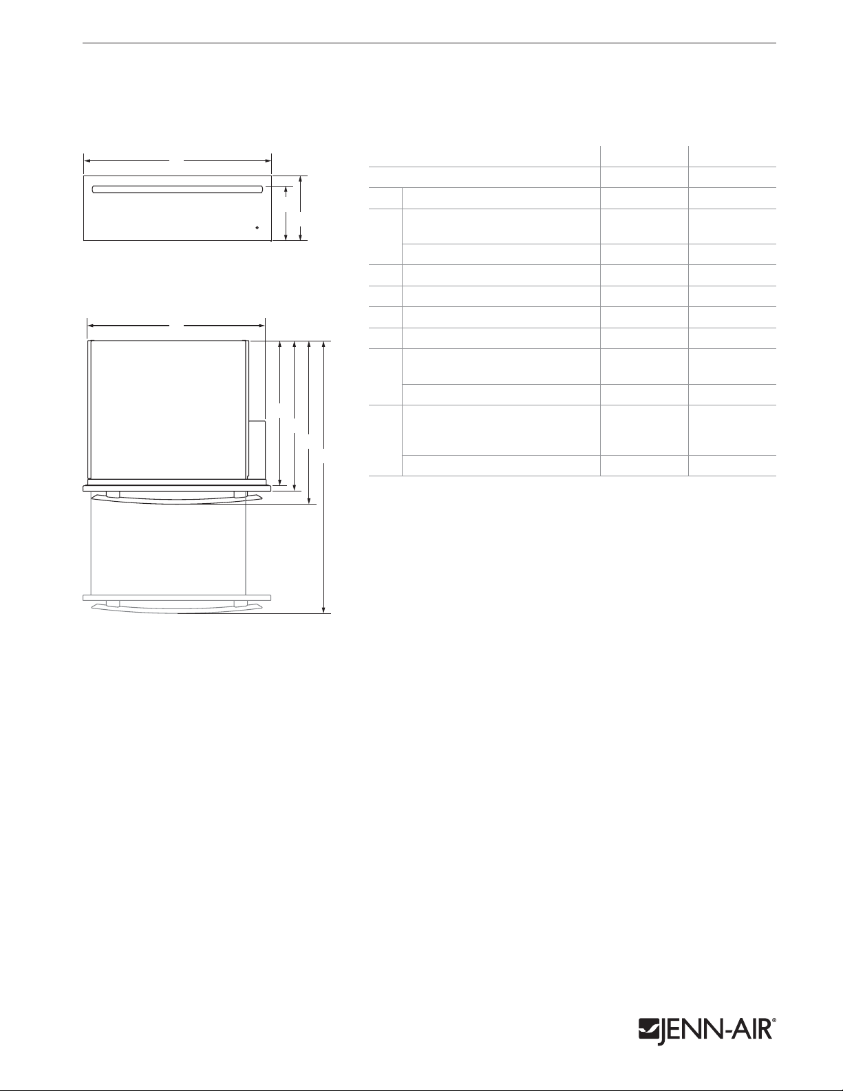
30" WARMING DRAWERS
JWD2030WS, JWD2030WX – 293⁄4" x 103⁄8" x 26"
PRODUCT DIMENSIONS
1 of 4
FRONT VIEW
A
MODEL # JWD2030WS JWD2030WX
in cm in cm
3
Overall width (max.) 29
B
C
A
Height to top of handle
Euro-Style (color-coordinating) 8
B
Pro-Style
Overall height (max.) 10
C
Width of recessed warming drawer 28
D
Depth of recessed warming drawer 23
E
Depth with drawer
F
®
Stainless — — 91⁄8 23.3
⁄4 75.6 293⁄4 75.6
7
⁄8 22.6 87⁄8 22.6
3
⁄8 26.3 103⁄8 26.3
1
⁄4 71.8 281⁄4 71.8
1
⁄8 58.8 231⁄8 58.8
24 61.0 — —
Depth with handle
Euro-Style (color-coordinating) 26 66.2 26 66.2
G
Pro-Style
E
F
G
H
Depth with drawer fully open
including handle
H
Euro-Style (color-coordinating) 45
Pro-Style
®
Stainless — — 261⁄2 67.4
3
⁄8 115.2 453⁄8 115.2
®
Stainless — — 457⁄8 116.4
TOp VIEW
Product dimension, cutout and installation specifications are provided for planning purposes only. Before installing
any product, be sure to verify cutout dimensions and electrical/gas connections as actual product dimensions may vary.
JRC120061A 07/2012
Page 2
JENN-AIR® DETAILED PLANNING DIMENSIONS
A
Back of Cabinet
F
D
C
D
E
C
e
B
e
Power Cord Location
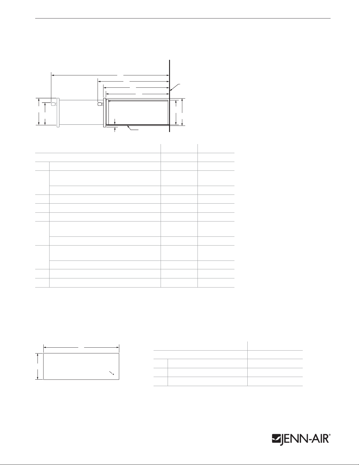
30" WARMING DRAWERS
JWD2030WS, JWD2030WX – 293⁄4" x 103⁄8" x 26"
DIMENSIONS AS INSTALLED
F
G
H
I
Back of
Cabinet
2 of 4
A
B
SIDE VIEW
C
Bottom of Cutout
D
E
MODEL # JWD2030WS JWD2030WX
Height to top of drawer (max.) 9
A
in cm in cm
3
⁄4 24.8 93⁄4 24.8
Height to top of handle
Euro-Style (color-coordinating) 8
B
Pro-Style
Height of drawer extending below cutout
C
Height of recessed warming drawer 9 22.9 9 22.9
D
Height of warming drawer flange 9
E
®
Stainless — — 85⁄8 21.8
1
⁄4 21.1 81⁄4 21.1
5
⁄8 1.5
7
⁄8 25.1 97⁄8 25.1
5
⁄8 1.5
Depth with drawer fully open including handle
Euro-Style (color-coordinating) 45
F
Pro-Style
®
Stainless — — 457⁄8 116.4
3
⁄8 115.2 453⁄8 115.2
Depth with handle
Euro-Style (color-coordinating) 26 66.2 26 66.2
G
Pro-Style
Depth with drawer 24 61.0 — —
H
Depth of recessed warming drawer 23
I
®
Stainless — — 261⁄2 67.4
1
⁄8 58.8 231⁄8 58.8
PANEL DIMENSIONS
A
B
C
MODEL # JWD2030WX
Width (min.-max.) 29-29
A
Height (min.-max.) 9
B
Hole for indicator light lens (dia.)
C
in cm
3
⁄4 73.7-75.6
1
⁄16-105⁄16 23.0-26.2
5
⁄16 0.8
LOCATION OF INDICATOR LIGHT LENS
Locate lens directly in front of indicator light.
pANEL THICKNESS
Depth of flat or raised panel will vary depending on
surrounding cabinetry.
Product dimension, cutout and installation specifications are provided for planning purposes only. Before installing
any product, be sure to verify cutout dimensions and electrical/gas connections as actual product dimensions may vary.
JRC120061A 07/2012
Page 3

JENN-AIR® DETAILED PLANNING DIMENSIONS
A
Back of Cabinet
F
30" WARMING DRAWERS
JWD2030WS, JWD2030WX – 293⁄4" x 103⁄8" x 26"
OPENING/CLEARANCE DIMENSIONS
MODEL #
A
B
C
D
E
F
e
ELECTRICAL REQUIREMENTS
120 volt, 60 Hz, AC only, 15-amp fused, electrical circuit is required.
A dedicated circuit is recommended.
If the outlet is on the rear wall behind the warming drawer,
it must be recessed and located in the upper right-hand corner.
If outlet is located in an adjacent cabinet, drill a 13⁄8" (3.5 cm)
C
e
B
D
C
e
D
minimum diameter hole in the side wall or support surface
to access the power supply cord.
LOCATION REQUIREMENTS
Support surface must be solid, level and flush with the bottom of
the cabinet cutout. The warming drawer must be leveled before
completing installation.
3 of 4
JWD2030WS
JWD2030WX
in cm
Width of cabinet (min.) 30 76.2
1
Width of cutout 28
Height between cutouts (min.) 2
Height of cutout 9
Bottom of cutout to floor
(recommended)
⁄2 72.4
1
⁄2 6.4
1
⁄8 23.2
1
8
⁄4 21.0
Bottom of cutout to floor (min.) 5 12.7
Depth of cutout (min.) 24 61.0
Recommended outlet location
FRONT VIEW
SIDE VIEW
Power Cord Location
BACK VIEW
E
Back of Cabinet
F
Product dimension, cutout and installation specifications are provided for planning purposes only. Before installing
any product, be sure to verify cutout dimensions and electrical/gas connections as actual product dimensions may vary.
JRC120061A 07/2012
Page 4

JENN-AIR® DETAILED PLANNING DIMENSIONS
Back of Cabinet
G
Back of Cabinet
G
30" WARMING DRAWERS – FLUSh INSTALLATION
JWD2030WS, JWD2030WX – 293⁄4" x 103⁄8" x 24" (depth without handle)
OPENING/CLEARANCE DIMENSIONS
MODEL #
A
B
C
D
E
F
G
e
ELECTRICAL REQUIREMENTS
120 volt, 60 Hz, AC only, 15-amp fused, electrical circuit is required.
A dedicated circuit is recommended.
If the outlet is on the rear wall behind the warming drawer,
it must be recessed and located in the upper right-hand corner.
If outlet is located in an adjacent cabinet, drill a 13⁄8" (3.5 cm)
minimum diameter hole in the side wall or support surface
to access the power supply cord.
LOCATION REQUIREMENTS
Support surface must be solid, level and flush with the bottom of
the cabinet cutout. The warming drawer must be leveled before
completing installation.
FLUSH INSTALLATION REQUIREMENTS
A 25" (63.6 cm) minimum cutout depth is required.
These dimensions will result in a 113⁄16" (4.6 cm) reveal on the top,
a 1⁄8" (0.3 cm) reveal on the sides and a 5⁄16" (0.8 cm) reveal on the
bottom of the warming drawer.
The front face of the cleats and platforms will be visible and should
be treated as a finished surface.
D
FRONT VIEW
A
7
⁄8" (2.2 cm)
Platform*
B
3
⁄4" (1.9 cm)
Side Cleats*
e
C
E
F
Back of Cabinet
4 of 4
JWD2030WS
JWD2030WX
in cm
Width of flush inset cutout (min.) 30 76.2
1
Width of opening (min.) 28
Height between cutouts (min.) 2
Height of opening (min.) 9
⁄2 72.4
1
⁄2 6.4
1
⁄8 23.2
Height of flush inset cutout (min.) 10 25.4
Bottom of cutout to floor
(recommended)
1
8
⁄4 21.0
Bottom of cutout to floor (min.) 5 12.7
Depth of cutout (min.) 25 63.5
Recommended outlet location
G
SIDE VIEW
G
Side Cleat*
1" (2.5 cm)
TOp VIEW
* Cleats and platform must be recessed 1" (2.5 cm) from the front of the cabinet.
Product dimension, cutout and installation specifications are provided for planning purposes only. Before installing
any product, be sure to verify cutout dimensions and electrical/gas connections as actual product dimensions may vary.
Side Cleat*
Power Cord Location
BACK VIEW
JRC120061A 07/2012
 Loading...