

Page 1
JENN-AIR® DETAILED PLANNING DIMENSIONS
K
A
M
N
O
P
L L
A
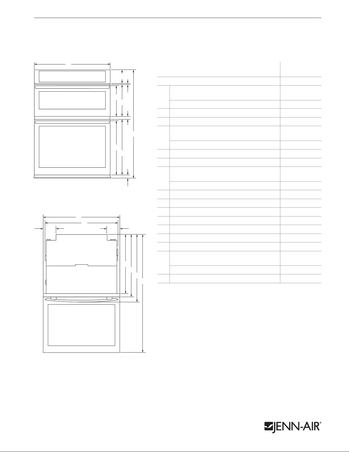
30" COMBINATION MICROWAVE/WALL OVENS
JMW3430D, JMW2430D – 30" x 433⁄4" x 255⁄16"
PRODUCT DIMENSIONS
MODEL #
Overall width
Pro-Style® Stainless or Euro-Style Stainless
A
Floating Glass 2915⁄16 76.1
Height of control panel
B
Space between control panel and door
C
Height to top of microwave oven handle
Pro-Style
D
Euro-Style (color-coordinating) 12
Height of microwave oven door
E
Space between doors 11⁄8 2.9
F
Height to top of oven handle
Pro-Style
G
Euro-Style (color-coordinating)
Height of oven door
H
Height of trim
I
Overall height
J
Width of recessed oven 287⁄16 72.2
K
Width of conduit channel 415⁄16 12.5
L
Depth of recessed oven 231⁄4 59.0
M
Depth with doors 243⁄8 61.9
N
Depth with handles
Pro-Style
O
Euro-Style (color-coordinating)
Depth with door fully open 453⁄8 115.3
P
FRONT VIEW
B C
D
E
F
J
G
H
I
A
K
L L
M
N
O
P
®
Stainless 12
®
Stainless 21
®
Stainless 26
1 of 4
JMW3430D
JMW2430D
in cm
30
76.2
51⁄2 14
1
⁄2 1.2
3
⁄16 31.0
3
⁄16 31.0
1211⁄16 32.3
5
⁄8 55.0
217⁄16 54.4
221⁄8 56.2
111⁄16 4.3
433⁄4 111.1
3
⁄8 67.0
255⁄16 64.3
TOP VIEW
IMPORTANT: Dimensional specifications are provided for planning purposes only.
Do not make any cutouts based on this information. Refer to the Installation Guide before
selecting cabinetry, verifying electrical/gas connections, making cutouts or beginning installation.
All Jenn-Air® appliances are appropriately UL, CUL or CSA approved.
8610AdZw915
Page 2
JENN-AIR® DETAILED PLANNING DIMENSIONS
K
A
M
N
O
L L
C
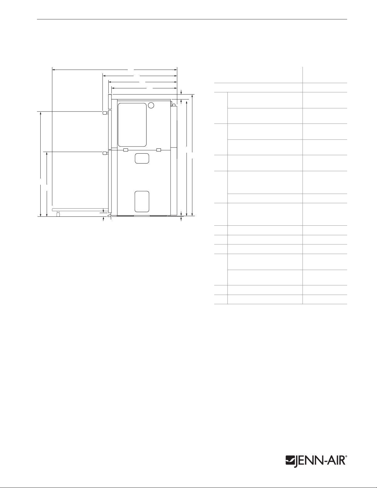
30" COMBINATION MICROWAVE/WALL OVENS
JMW3430D, JMW2430D – 30" x 433⁄4" x 255⁄16"
DIMENSIONS AS INSTALLED
2 of 4
A
B
SIDE VIEW
H
I
J
MODEL #
K
Height to top of upper handle
D
Pro-Style
A
Euro-Style
®
Stainless 36
(color-coordinating) 36
Height to top of lower handle
Pro-Style
B
F
G
Euro-Style
(color-coordinating)
Height of trim extending
C
below cutout
®
Stainless 23
Height from top of recessed
oven to top of control panel
D
JMW3430D
JMW3430D
JMW2430D
in cm
1
⁄2 92.7
1
⁄2 92.7
3
⁄8 59.3
231⁄8 58.7
111⁄16 4.3
21⁄2
6.3
JMW2430D 215⁄16 7.4
E
Height from bottom of
recessed oven foot to bottom
E
3
⁄16 0.5
of oven vent
Height of recessed oven 41 104.2
F
Height to top of control panel
G
Depth with door fully open 453⁄8 115.3
H
Depth with handles
Pro-Style
I
Euro-Style
®
Stainless 26
(color-coordinating)
Depth with doors 243⁄8 61.9
J
Depth of recessed oven 231⁄4 59.0
K
433⁄4 111.1
3
⁄8 67.0
255⁄16 64.3
IMPORTANT: Dimensional specifications are provided for planning purposes only.
Do not make any cutouts based on this information. Refer to the Installation Guide before
selecting cabinetry, verifying electrical/gas connections, making cutouts or beginning installation.
All Jenn-Air® appliances are appropriately UL, CUL or CSA approved.
8610AdZw915
Page 3

K
A
M
N
O
P
L L
A
D
G
E
H
B C
F
J
C
H
J
K
F
G
I
E
D
A
B
C*
G
G
e
e
D
F
E
F
B
C*
e
e
F
A
H
JENN-AIR® DETAILED PLANNING DIMENSIONS
3 of 4
30" COMBINATION MICROWAVE/WALL OVENS
JMW3430D, JMW2430D – 30" x 433⁄4" x 255⁄16"
OPENING/CLEARANCE DIMENSIONS
A
D
C*
B
e e
E
JMW3430D
MODEL #
JMW2430D
in cm
Width of cabinet (min.) 30 76.2
A
Width of cutout 281⁄2 72.4
B
Height of cutout
C*
(recommended)
Top of cutout to bottom
D
of upper cabinet door (min.)
Bottom of cutout to top
E
of lower cabinet door (min.)
Bottom of cutout to floor
F
415⁄16 104.9
Depth of cutout (min.) 24 61.0
G
e
Recommended junction box location
* Will fit cutout height from 41" (104.1 cm) to 41
21⁄4 5.7
11⁄2 3.8
4-
10.2-
191⁄4
48.9
1
⁄2" (105.4 cm).
ELECTRICAL REQUIREMENTS
240 volt, 40-amp fused, grounded circuit is required. A dedicated
circuit is required.
The length of conduit provided is for serviceability. Do not cut
the conduit. The junction box should be located 3" (7.6 cm)
G
maximum below the support surface. Drill a 1" (2.5 cm) minimum
diameter hole in the right rear or left rear corner of the support
surface for access to the junction box.
F
FRONT VIEW
SIDE VIEW
Power Supply
Location
BACK VIEW
IMPORTANT: Dimensional specifications are provided for planning purposes only.
Do not make any cutouts based on this information. Refer to the Installation Guide before
selecting cabinetry, verifying electrical/gas connections, making cutouts or beginning installation.
All Jenn-Air® appliances are appropriately UL, CUL or CSA approved.
8610AdZw915
Page 4

JENN-AIR® DETAILED PLANNING DIMENSIONS
B
D
e
e
A
3
4
" (1.9
cm) Side
3
4
" (1.9
cm) Side
2" (5.1 cm)
Top Cleat*
E
C
E
F
ee
F
Side Cleat*
13/8" (3.5 cm)
Side Cleat*
E
1
1
2
" (3.8 cm)
Platform*
Power Supply Location
A
B
9
/16" (1.4 cm)
Top Cleat*
11
/16" (1.7 cm)
Side Cleat*
1
/2" x 2" (1.3 x 5.1 cm)
Spacer (entire depth
of cutout)
D
C
11
/16" (1.7 cm)
Side Cleat*
F
K
A
M
N
O
P
L L
A
D
G
E
H
B C
F
J
C
H
J
K
F
G
I
E
D
30" COMBINATION MICROWAVE/WALL OVENS – FLUSH INSTALLATION
JMW3430D, JMW2430D – 30" x 433⁄4" x 243⁄8" (depth without handles)
4 of 4
OPENING/CLEARANCE DIMENSIONS
5
/8" (1.6 cm)
Top Cleat*
A
B
C
D
11
/16" (1.7 cm)
Side Cleat*
1
/2" x 2" (1.3 x 5.1 cm)
Spacer (entire depth
of cutout)
FRONT VIEW
11
/16" (1.7 cm)
Side Cleat*
e e
E
SIDE VIEW
JMW3430D
MODEL #
JMW2430D
in cm
Width of flush inset cutout
A
(min.)
Width of opening (min.) 287⁄8 73.3
B
Height of flush inset cutout
C
(min.)
Height of opening (min.) 4311⁄16 110.9
D
Bottom of cutout to floor
E
Depth of cutout (min.) 25 63.5
F
e
Recommended junction box location
ELECTRICAL REQUIREMENTS
240 volt, 40-amp fused, grounded circuit is required. A dedicated
circuit is required.
The length of conduit provided is for serviceability. Do not cut
the conduit. The junction box should be located 3" (7.6 cm)
maximum below the support surface. Drill a 1" (2.5 cm) minimum
diameter hole in the right rear or left rear corner of the support
surface for access to the junction box.
FLUSH INSTALLATION REQUIREMENTS
F
A 25" (63.5 cm) minimum cutout depth is required.
These dimensions will result in a 1⁄4" (0.6 cm) reveal on the top,
a 1⁄4" (0.6 cm) reveal on the sides and a 1⁄8" (0.3 cm) reveal on
the bottom of the wall oven.
The front face of the cleats and spacers will be visible and
should be treated as a finished surface.
301⁄4 76.8
445⁄16 112.5
45⁄8-
191⁄4
11.7-
48.9
Power Supply
Location
F
Side Cleat*
Side Cleat*
13/8" (3.5 cm)
TOP VIEW
* Cleats and spacers must be recessed 13⁄8" (3.5 cm) from the front of the cabinet.
BACK VIEW
IMPORTANT: Dimensional specifications are provided for planning purposes only.
Do not make any cutouts based on this information. Refer to the Installation Guide before
selecting cabinetry, verifying electrical/gas connections, making cutouts or beginning installation.
All Jenn-Air® appliances are appropriately UL, CUL or CSA approved.
8610AdZw915
 Loading...