

Page 1
JENN-AIR® DETAILED PLANNING DIMENSIONS
115°
A
A
H
I
J
K
G
A
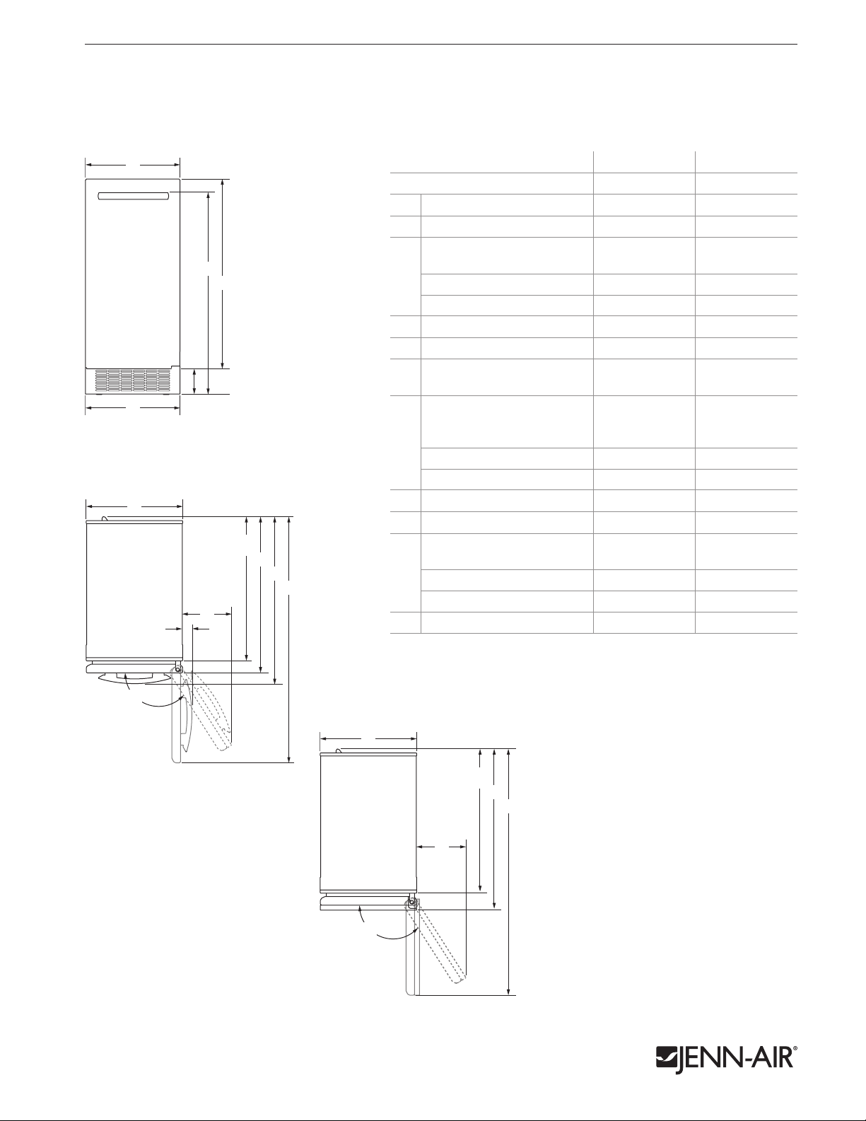
15" ICE MACHINES
JIM158XYR – 147⁄8" x 333⁄4" x 241⁄4"
JIM158XYC – 147⁄8" x 333⁄4" x 243⁄4"
PRODUCT DIMENSIONS
MODEL # JIM158XYR JIM158XYC
Width 147⁄8 37.8 147⁄8 37.8
A
Width of grille 143⁄4 37.6 143⁄4 37.6
B
Height to top of handle
C
D
E
B
FRONT VIEW
A
H
I
J
K
F
G
115°
Pro-Style® Stainless*
C
Euro-Style Stainless 311⁄2 79.9 — —
Custom panel — —
Height of door 297⁄8 75.9 297⁄8 75.9
D
Height of grille 4 10.1 4 10.1
E
Width from side of ice machine
F
to door fully open
Width from side of ice machine
to handle – door open 90°
Pro-Style® Stainless*
G
Euro-Style Stainless 17⁄8 4.7 — —
Custom panel — —
Depth without door
H
†
Depth with door
I
Depth with handle
Pro-Style® Stainless*
J
Euro-Style Stainless 26 65.9 — —
Custom panel — —
Depth with door open 90°
K
* Requires optional Pro-Style® Stainless handle kit – W10591217.
Each kit includes one Pro-Style® badge and one handle.
**For custom panel models, this depends on handle chosen.
†
Includes recommended 3⁄4" (1.9 cm) custom panel thickness (JIM158XYC).
1 of 3
in cm in cm
313⁄4 80.6
—
**
—
**
7 17.7 67⁄8 17.4
23⁄8
6.0
—
**
—
**
223⁄8 56.7 223⁄8 56.7
241⁄4 61.5 243⁄4 62.9
261⁄2 67.3
—
**
—
**
38 96.6 38 96.6
TOP VIEW – JIM158XYR
TOP VIEW – JIM158XYC
115°
Product dimension, cutout and installation specifications are provided for planning purposes only. Before installing
any product, be sure to verify cutout dimensions and electrical/gas connections as actual product dimensions may vary.
H
I
K
F
7707dZw413
Page 2
JENN-AIR® DETAILED PLANNING DIMENSIONS
H
I
J
K
G
A
B
A
EF
D
B
C
A
A
EF
B
C
A
A
B
C
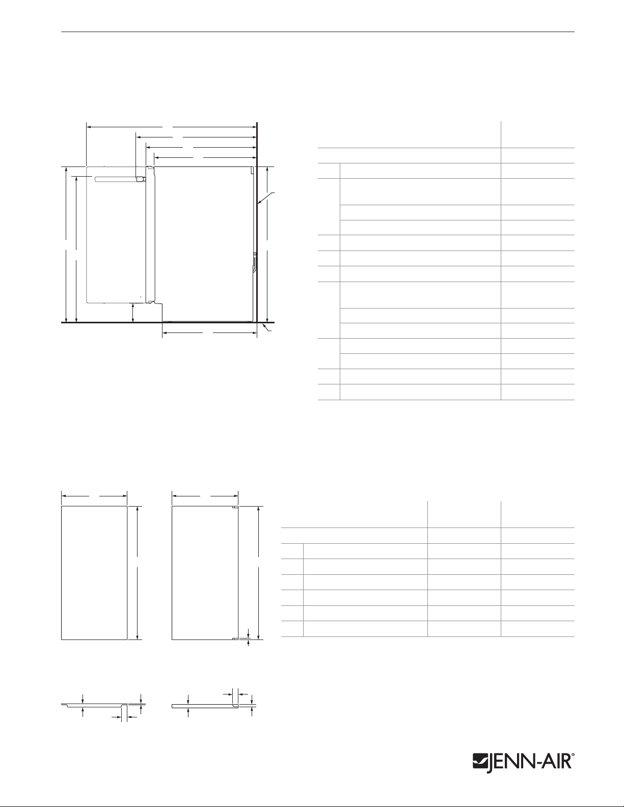
15" ICE MACHINES
JIM158XYR – 147⁄8" x 333⁄4" x 241⁄4"
JIM158XYC – 147⁄8" x 333⁄4" x 243⁄4"
DIMENSIONS AS INSTALLED
2 of 3
E
F
G
MODEL #
H
Height to top of door (min.)
A*
Wall
Height to top of handle (min.)
Pro-Style® Stainless**
B*
Euro-Style Stainless 311⁄2 79.9
Custom panel
Height to top of grille (min.)
A*
B*
D*
C*
Height of recessed ice machine (min.) 333⁄4 85.7
D*
Depth with door open 90° (min.)
E
Depth with handle (min.)
Pro-Style® Stainless**
C*
SIDE VIEW
I
Floor
PANEL DIMENSIONS
OPTION 1 – RAISED PANEL
(without hinge-side spacer)
OPTION 2 – FLAT PANEL
(with hinge-side spacer)
F
Euro-Style Stainless 26 65.9
Custom panel
Depth with door (min.) 241⁄4 61.5
G
Depth with custom panel (min.)
Depth without door (min.)
H
Depth of grille (min.)
I
* Add 1" (2.5 cm) to the height dimension when leveling legs are
fully extended.
** Requires optional Pro-Style® Stainless handle kit – W10591217.
Each kit includes one Pro-Style® badge and one handle.
†
For custom panel models, this depends on handle chosen.
‡
Includes recommended 3⁄4" (1.9 cm) custom panel thickness (JIM158XYC).
‡
JIM158XYR
JIM158XYC
in cm
333⁄4 85.6
313⁄4 80.6
† †
4 10.1
38 96.6
261⁄2 67.3
† †
25 63.5
223⁄8 56.7
203⁄8 51.8
B
FRONT VIEW FRONT VIEW
F
D
E
TOP VIEW TOP VIEW
Product dimension, cutout and installation specifications are provided for planning purposes only. Before installing
any product, be sure to verify cutout dimensions and electrical/gas connections as actual product dimensions may vary.
B
C
D
PANEL TYPE
OPTION 1
RAISED PANEL
OPTION 2
FLAT PANEL
in cm in cm
Width of panel 141⁄2 36.9 145⁄8 37.1
A
Height of panel 291⁄2 74.9 295⁄8 75.2
B
Height of notch — —
C
Width of routed edge/notch 11⁄4 3.2 11⁄8 3.0
D
Depth of panel
E
Depth of routed edge/notch
F
3
⁄4 1.9
1
⁄4 0.6
5
⁄8 1.5
3
⁄4 1.9
1
⁄2 1.3
CUSTOM PANEL REQUIREMENT
• Weight (max.): 8 lb (3.6 kg) • Thickness: 3⁄4" (1.9 cm)
HINGE-SIDE SPACER REQUIREMENTS
• Front spacer: 3⁄4" (1.9 cm) strip – install flush with face of adjacent cabinet
• Back spacer: 3⁄4" (1.9 cm) strip – install 6" (15.2 cm) from back wall
7707dZw413
Page 3

JENN-AIR® DETAILED PLANNING DIMENSIONS
Floor
Wall
J
Floor
Back Wall
F
A
J
e
w
B
G
I
C
D
H
EE
M
L
15" ICE MACHINES
JIM158XYR – 147⁄8" x 333⁄4" x 241⁄4"
JIM158XYC – 147⁄8" x 333⁄4" x 243⁄4"
3 of 3
OPENING/CLEARANCE DIMENSIONS
MODEL #
A
F
D
w
H
FRONT VIEW
J
SIDE VIEW
Floor
N
BACK VIEW
B
e
Wall
O
C
G
I
Width (min.) 15 38.1
Width without hinge side spacer option (min.) 15 38.1
A
Width with hinge side spacer option (min.) 153⁄4* 40.0*
Width of outlet location 6 15.0
B
Outlet location – distance from side 1 2.5
C
Width of water connection location 31⁄2 8.9
D
Minimum width from hinged side of ice
machine to fixed wall – door open 90°
EE
Minimum width from hinged side of ice machine
E
to fixed wall – door fully open 180° (JIM158XYR)
Minimum width from hinged side of ice machine
to fixed wall – door fully open 118° (JIM158XYC)
Height (min.) 34 86.4
F
Height of outlet location 8 20.3
G
Height of water connection location 9 22.9
H
Outlet location – distance from bottom 12 30.5
I
Depth of cabinet (min.) 24 61.0
J
Water line location – distance from side 23⁄4 7.0
K
Power supply – distance from side 35⁄8 9.3
L
Drain hose – distance from side 33⁄8 8.7
M
Power supply – distance from bottom 11⁄8 2.9
N
Drain hose – distance from bottom 71⁄4 18.6
O
Water line location – distance from bottom 143⁄8 36.7
P
e
Recommended electrical connection location
w
Recommended water connection location
* Install 3⁄4" (1.9 cm) front hinge-side spacer flush with face of adjacent cabinet
and 3⁄4" (1.9 cm) back hinge-side spacer 6" (15.2 cm) from back wall.
ELECTRICAL REQUIREMENTS
115 volt, 60 Hz, AC only, 15- or 20-amp fused, grounded circuit is required.
A dedicated circuit is recommended. Use an outlet that cannot be turned off
by a switch. Do not use an extension cord.
WATER PRESSURE REQUIREMENTS
A cold water supply with water pressure between 30 and 120 psi (207 and
K
P
827 kPa) is required to operate the ice maker. Call a licensed, qualified plumber with
any questions about the water pressure.
Reverse Osmosis Water Supply
IMPORTANT: The use of a reverse osmosis system with this product is not
recommended. However if you do use reverse osmosis, follow these instructions.
Reverse osmosis systems will not work at all with auxillary drain pump 1901A.
IMPORTANT: The pressure of the water coming out of a reverse osmosis system
going to the water inlet valve of the ice machine needs to be between 30 and 120
psi (207 and 827 kPa).
If a reverse osmosis water filtration system is connected to the cold water supply, the
water pressure to the reverse osmosis system needs to be a minimum of
40 to 60 psi (276 to 414 kPa).
GRAVITY DRAIN SYSTEM REQUIREMENTS
The center of the drain should be 23" (58.4 cm) from the front of the door
and centered 73⁄8" (18.6 cm) from left to right.
JIM158XYR
JIM158XYC
in cm
2 5.1
131⁄4 33.7
67⁄8 17.4
Product dimension, cutout and installation specifications are provided for planning purposes only. Before installing
any product, be sure to verify cutout dimensions and electrical/gas connections as actual product dimensions may vary.
7707dZw413
 Loading...