

JENNAIR JIM1550ACX, JIM1550ARB, JIM1550ARS, JIM1550ARW Owner's Manual

I CE M AKER
OWNER’S
GUIDE
TABLE OF C O NTENTS
Introduction..............................................................................2
Safety ....................................................................................... 3
Installation............................................................................4-9
Operation................................................................................10
Care and Cleaning .......................................................11-12
Before Calling for Service .........................................13-18
Warranty..................................................................................20
Guide du Propriétaire ........................................................21
Guía del Propietario ...........................................................41
41007621
Introduction
Congratulations on the purchase of a Jenn-Air ice
maker.
We appreciate your purchase decision and feel
confident you will be happy with this appliance for
years to come. For best results, please read this guide
carefully. You will find instructions on the proper
operation and maintenance of your ice maker.
Should you ever need future assistance with your ice
maker, a complete model and serial number recorded
in the spaces below will be extremely helpful. These
numbers are found on the data plate inside on the
lower front of the ice maker cabinet.
Model Number ________________________
Serial Number ________________________
Purchase Date ________________________
Dealer Name _________________________
Dealer Address________________________
Dealer Phone _________________________
Before Calling for Service . . .
If something seems unusual, please check the “Before
Calling For Service” section, which is designed to help
you solve basic problems before calling a servicer.
What if These Features are Different
from Mine?
This book is intended to show the variety of features
that are available in the product line. If you have
questions, write us (include your model number and
phone number) or call:
Maytag Services
Attn: Jenn-Air CAIR®Center
P.O. Box 2370
Cleveland, TN 37320-2370
U.S.A. and Canada 1-800-JENNAIR
1-800-688-2080 (U.S.A. TTY for hearing
or speech impaired)
(Mon.-Fri., 8 a.m.-8 p.m. Eastern Time)
Internet: http://www.jennair.com
SM
(1-800-536-6247)
What You Need to Know About
Safety Instructions
Warning and Important Safety Instructions appearing in
this manual are not meant to cover all possible
conditions and situations that may occur. Common
sense, caution and care must be exercised when
installing, maintaining or operating this appliance.
Always contact your dealer, distributor, service agent or
manufacturer about problems or conditions you do not
understand.
Recognize Safety Symbols, Words,
Labels
DANGER
DANGER – Immediate hazards which WILL result in
severe personal injury or death.
WARNING
WARNING – Hazards or unsafe practices which
COULD result in severe personal injury or death.
CAUTION
CAUTION – Hazards or unsafe practices which COULD
result in minor personal injury.
2
Important Safety Instructions
WARNING
•When using your appliance, always follow basic
precautions.
• Use the ice maker only for its intended purpose.
•To prevent possibility of hazard due to electrical
shock, never plug the ice maker into a receptacle
which has not been grounded adequately and in
accordance with the local and national electrical
codes. See warning and the grounding
instructions that follow.
• Disconnect power to the ice maker before cleaning,
servicing or replacing a light bulb.
• In case of power failure, minimize door openings.
• Any electrical service cord that becomes frayed or
damaged should be immediately repaired or
replaced. Never unplug your appliance by pulling on
the power cord.
•Your ice maker should not be operated in the
presence of gasoline or other flammable vapors and
liquids.
WARNING
•This appliance is designed to operate on a normal
115 volt, 15 amp, 60 cycle line. There should be a
separate, grounded circuit serving this appliance
only. Do not use an extension cord. Do not use
any device that will alter the electrical
performance of this appliance.
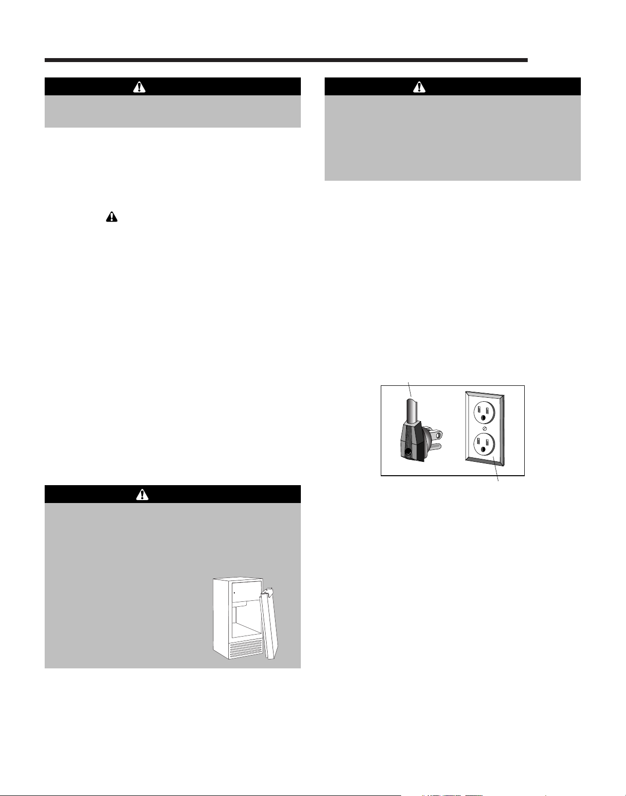
This appliance is equipped with a three-pronged
grounding plug for your protection against possible
electrical shock hazards. It must be plugged into a
grounding receptacle. Where a standard two-prong
wall receptacle is encountered, it is the personal
responsibility and obligation of the customer to have it
replaced with a properly grounded three-prong wall
receptacle. Do not under any circumstances, cut or
remove the third (ground) prong from the power cord.
Do not use an adapter plug.
Power Supply Cord With
3-prong Grounding Plug
• Children should not climb, hang or stand on or in
this refrigeration product.
• Read and follow manufacturer’s warnings on ice
machine cleaner products. Personal injury can result
when used improperly.
DANGER
Child entrapment and suffocation are not problems
of the past. Junked or abandoned refrigeration
products are still dangerous…even if they will sit for
“just a few days.” If you are getting rid of your old
refrigeration products, please follow the instructions
below to help prevent
accidents.
•Take off the doors.
•Leave the shelves in place
so that children may not
easily climb inside.
Grounding Type
Wall Receptacle
Save These Instructions for Future Reference
3
Installation
Materials Needed
1
•
⁄8" Allen wrench
5
⁄16" socket
•
• Phillips screwdriver
•Putty knife
• Carpenter’s level
1
⁄4" O.D. copper tubing for water supply
•
5
•
⁄8" I.D. plastic tubing and hose clamp
(for gravity drain)
Select Location
The ice maker was designed to be installed under the
counter. Its proper location will ensure peak
performance. Choose a location indoors, away from
heat and out of direct sunlight. Best performance will
be maintained when installed within the following
parameters:
Ideal Ambient
Temperature Range
Built-In..........................................................55-80° F
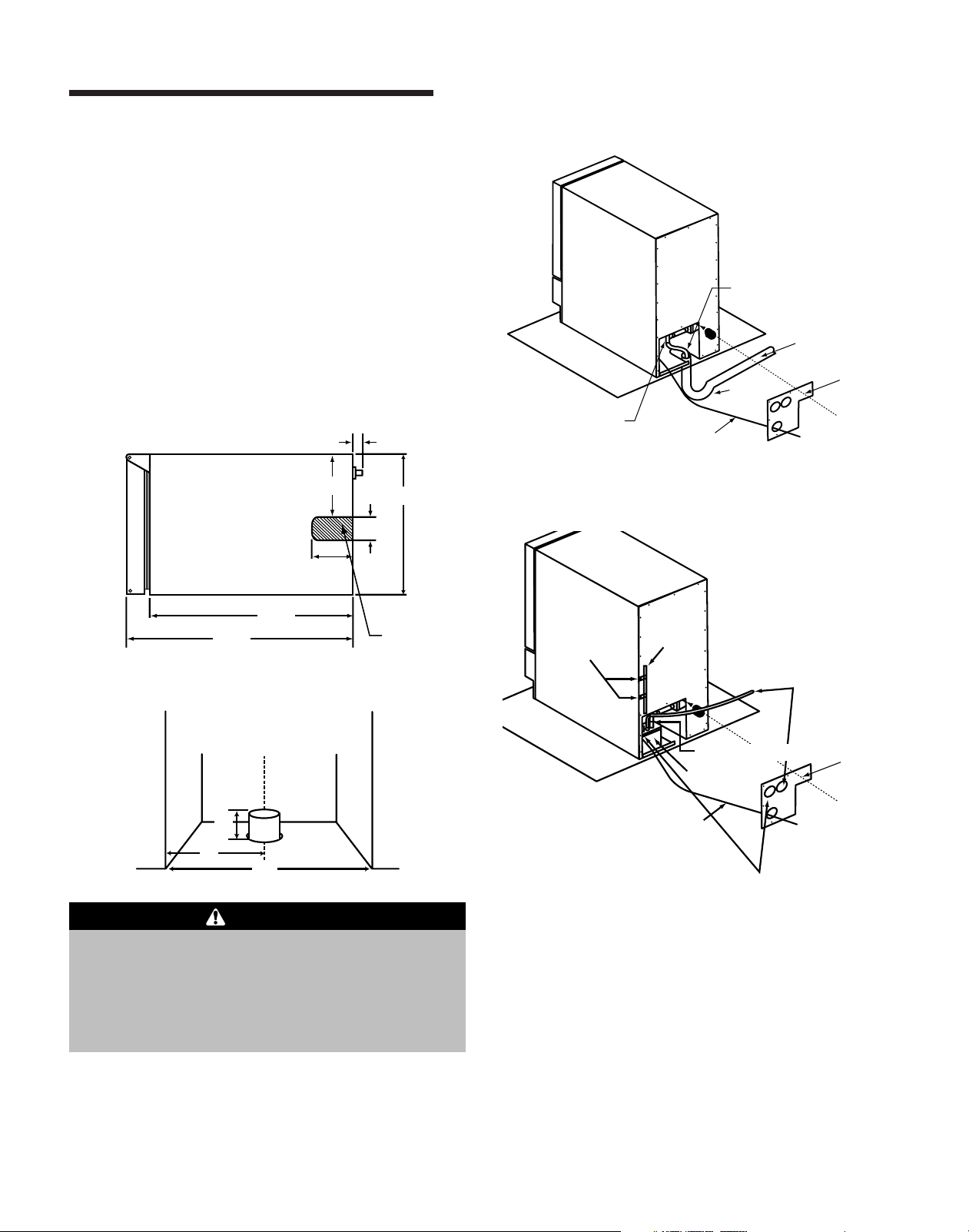
Cabinet Clearance
The ice maker may be enclosed on the sides, rear and
top. The front should be open and clear of any
obstructions.
Do not obstruct air flow through the lower front
grille area.
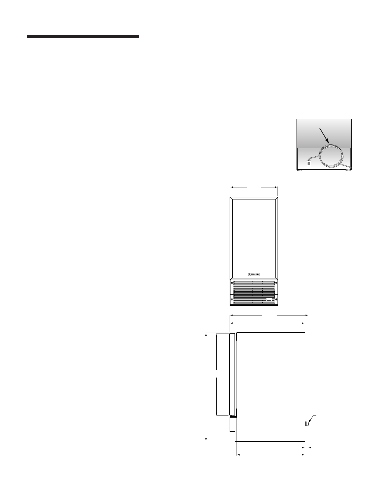
NOTE: Install the ice maker so that it can be
moved forward if service is
ever required. Do this by
adding enough copper tubing to
Service
Loop
create a service loop.
Use care to avoid kinks in tubing
when creating the service loop.
Dimensions
3
14
⁄4"
NOTE: Ice maker will not perform correctly in ambient
temperatures less than 55° F.
34
3
24
⁄4"
1
23
⁄2"
5
25
⁄8"
1
⁄4"
Supplied
Water Line
Fitting
1
1
⁄4"
21
1
8"
⁄
4
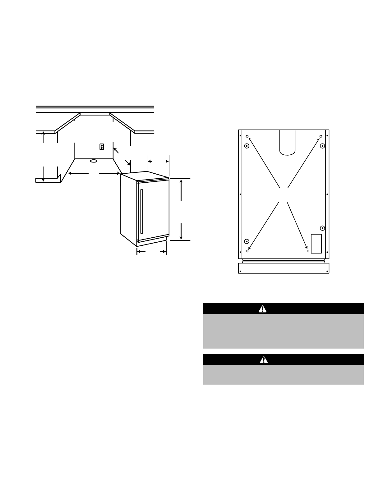
Cabinet Cut-Out Dimensions
and Specifications
Cut-out Height: 34
Cut-out Width: 15"
Cut-out Depth: 24" minimum
1
34
⁄2" Min.
to
1
35
⁄4" Max.
Water supply should enter
cutout from right rear wall.
1
⁄2" minimum
Locate outlet
on back wall
to local codes.
Floor Drain
15"
24"
Min.
24
3
⁄
4"
1
34
⁄4" Min.
Adjustable
to 35"
Leveling Legs
Install leveling legs (located in the literature pack):
•With at least 2 people, tip ice maker backwards
until there is approximately 12" of clearance
between the floor and the ice maker.
• Screw one front leveling leg into the screw
impression found in each corner. Leveling legs
should be screwed in until snug.
Screw
Impressions
14
3
⁄4"
of Unit
• Secure the door and repeat the above
procedures to install the rear leveling legs.
WARNING
Bottom
• One person should not attempt to tilt the ice maker
by themself. Have someone else assist to prevent
the ice maker from falling during leveling leg
installation.
CAUTION
• The ice maker should remain upright at least
30 minutes prior to plugging it in.
Level the Ice Maker
Using a carpenter’s level, check to be sure the ice
maker is level from side to side and from front to back.
Leveling adjustments can be made by turning the
leveling legs counter-clockwise to increase height and
clockwise to reduce height.
NOTE: The ice maker should not wobble. Use shims
to add stability when needed.
5
Installation, cont.
Drainage
Your ice maker uses a gravity drain that requires
tubing from the back of the ice maker to a plumbed
connection to a sanitary sewer (see illustration to the
below). Remove the access panel to plumb in drain
connection. Gravity drain location for built-in units can
be within the shaded area shown. An optional drain
pump can be purchased for your ice maker if a gravity
drain is not accessible.
NOTE: Avoid kinks and check for proper water
drainage after ice maker installation.
OBSERVE AND FOLLOW ALL LOCAL CODES
WHEN INSTALLING ICE MAKER.
3
6
⁄4"
Front
of Unit
Top
of Unit
3
2
⁄8"
1
4
⁄16"
5
⁄8" I.D.
1
1
⁄4"
3
14
⁄4"
Gravity Drain
5
⁄8" I.D. Drain
Tubing and
Hose Clamp
Drain
Drain from
Ice Maker
Ice Maker
Trap
Power Cord
Drain Pump (sold separately)
1
1
⁄2" Drain Pipe
Access
Panel
1
21
⁄8"
1
23
⁄2"
Gravity Drain Location
Baseplate
Opening for
Gravity Drain
Locate standpipe
as shown.
3"
8"
15"
WARNING
•Failure to use adequate drainage system will result
in surrounding water damage and/or poor ice
production.
•Water damage due to the use of an inadequate
drainage system may cause mold/mildew growth.
Tubing
Clamps
Vent
Tube
Drain from Ice Maker
Drain Pump
Drain Pump
Power Cord
Vent tube goes through this
opening in the access panel.
Discharge tube goes
through this opening
in the access panel.
Access
Panel
To purchase an optional drain pump, contact the dealer
where you purchased the ice maker or Jenn-Air
Customer Assistance: 1-800-JENNAIR (1-800-536-
6247). Drain pump model number: JIMPUMPAXX.
NOTE: Detailed installation instructions are provided
with the drain pump kit.
6
Water Supply
Connecting to the Water Supply
• This ice maker must be connected to a potable,
active cold water supply line delivering water
pressure at a minimum pressure of 20 psi and
maximum of 120 psi.
•A water filter is recommended for this unit. A quality
in-line filter can remove particles as well as remove
taste and odors from water.
To purchase an in-line water filter, call our parts
specialists at 1-877-232-6771 inside the U.S.A. from
7 a.m. to 7 p.m. central time Monday through Friday.
Outside the U.S.A., contact your local appliance
dealer or parts distributor. Ask for water filter part
number 18001010.
NOTES:
• Softened water is not recommended. This will
produce mushy, cloudy ice cubes that will stick
together.
• De-ionized water is not recommended. This water
will not form solid ice cubes.
•Do not use any type of thread sealer.
Adapter
WARNING
•The water line fitting supplied with your ice maker
is to be used on a
only. Do not attach a plastic supply line to your
unit using this fitting.
1. Shut off the main water supply.
2. Drain water from the nearest faucet by the ice maker.
3. Use a shut-off valve between the ice maker and
the water supply. The shut-off should be a drilled
saddle valve. Do not use a self-tapping valve. The
valve should be installed in a vertical water pipe.
NOTE: If the valve is installed in a horizontal water
pipe, make the connection at the top side of the
pipe.
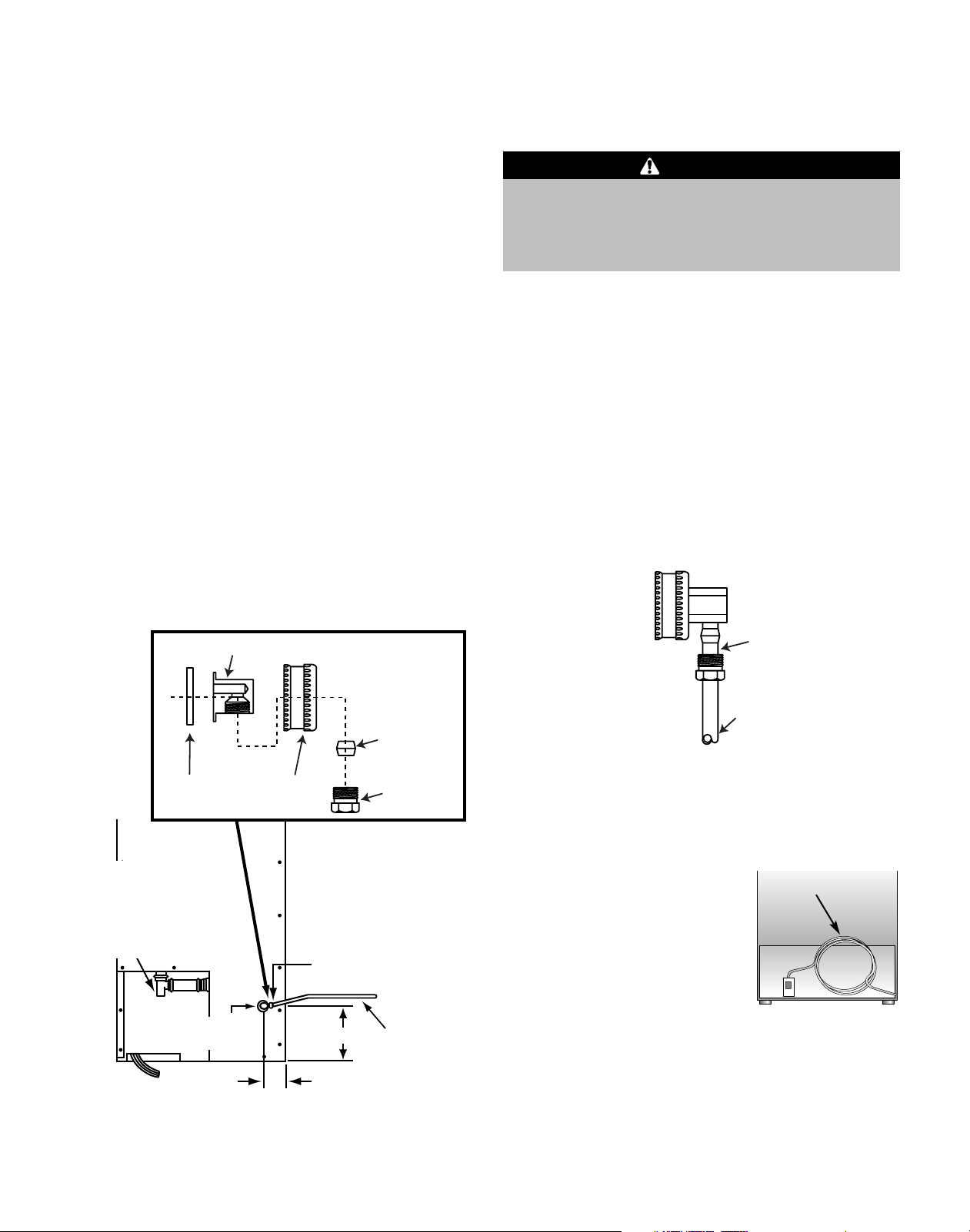
4. Water connection is made through a
right angle garden hose fitting (fitting is packaged
in the literature kit).
1
⁄4" copper water supply line
1
⁄4" compression
1
⁄4" Copper Water
Supply Line*
Rubber
Washer
5
⁄8" I.D. Drain
Tubing Barb
Make certain
all hose clamps
are secure.
Hose Fitting
Rear View of Ice Maker
Garden
Compression
Fitting
Compression
Valve
Compression Fitting
1
5
⁄2"
1
2
⁄8"
Fitting
Nut
1
⁄4" Tubing
from Cold
Water Line
From water
supply to
ice maker
* Supplied by Customer
In compliance with local codes and ordinances,
1
use
⁄4" O.D. copper tubing from the cold water line
and the ice maker.
NOTE: Install the ice
maker so that it can be
Service
Loop
moved forward if service is
ever required. Do this by
adding enough copper tubing
to create a service loop.
Use care to avoid kinks in
tubing when creating the service loop.
5. Turn main water supply on.
6. Flush the water line for any foreign material and
check for leaks.
7. Make sure there are no sharp bends or kinks in the
water line.
7

Installation, cont.
Reversing the Door
WARNING
• Disconnect power to the ice maker before
reversing the door.
1. Turn OFF the ice maker
and disconnect the
power. Remove top
hinge pin with a
1
⁄8" Allen wrench.
Remove door by pulling
it out and upward off
bottom hinge pin. Set
aside, face down on
surface that will not
scratch the finish.
Remove the small plastic washer from bottom
hinge pin.
2. Remove the six small
plastic hole plugs from the
left hand hinge holes
using the putty knife.
Using a
wrench or nut-driver,
remove bottom hinge.
Reinstall hinge, moving it
to the top left hand side.
Using a
from the top left hinge, and install in top right
hinge. Now move top right hinge to left bottom.
Flip the door over and reinstall the small plastic
washer on the bottom hinge pin. Install hole plugs
in right side.
5
⁄16" socket,
1
⁄8" Allen wrench, remove the hinge pin
Top of
Unit
Out
Hinge
Bracket
Up
Hole Plugs
Move
Hinge
Pin
Realigning the door may be necessary. Using a
Allen wrench, loosen the two screws on the top
and bottom adjustable door hinge bracket. Adjust
the door to proper alignment. Make sure door
gasket seals fully against the cabinet front.
Retighten screws after making adjustments.
4. Plug the ice maker in and turn the control
back to the ON setting.
1
⁄8"
Installing the Custom Door
Panel (select models)
WARNING
• Disconnect power to ice maker before installing
the custom door panel.
The dimensions for a decorative custom door panel are:
3
⁄4" Width
14
5
25
⁄8" Height
3
⁄4" Thickness (maximum)
1. Turn off the ice maker and
disconnect the power.
1
2. Remove
screw (A) from the
top hinge. Remove
the door off of the
lower hinge, noting
washer location.
3. Remove the door
seal (B) to expose the screw
holes.
⁄8" set
A
B
3. Reinstall the door by
locating it over the
bottom hinge pin and
pushing down and in.
Reinstall the top
hinge pin. Check the
door for proper
alignment. The top
and sides of the door
should run parallel to
the top and side edges
of the cabinet. Some
misalignment is acceptable, but the door gasket
must seal fully against the cabinet.
8
Hinge
Bracket
In
Down
Hinge
Pin
Top of
Unit
Custom Handle
1. A custom handle (not supplied) must be installed.
2. Drill pilot holes through the custom panel to match
the handle. Countersink the holes on the back of
the panel.
3. Attach the custom handle to the front door panel
assembly.
NOTE: The custom handle screws should be installed
through custom panel and into the custom handle. The
screw heads should be countersunk so the inside panel
surface can be installed flush with the ice maker door.

Wood Screws
Attach the Wood Panel to the
1. #8 pan head wood screws are recommended to
properly secure the custom wood panel to the ice
maker door.
2. A total of 10 screws are needed.
3. Use only pan head screws.
4. Be sure the screw length is NOT longer than the
wood thickness at the screw locations.
5. Use the following pilot hole drill sizes.
Type of Pilot Hole Drill Size for
Wood #8 Pan Head Wood Screws
Hardwood
Softwood
3
⁄32" (.23 cm)
5
⁄64" (.20 cm)
Prepare the Wood Panel
3
14
⁄4"
5
25
⁄8"
(65.07 cm)
(37.47 cm)
10 Pilot Hole
Locations
Custom panel
thickness:
5
⁄8" to 3⁄4"
(1.57-1.91 cm)
Ice Maker Door
1. Place the custom wood panel on a non-abrasive
surface, protected by towels or rugs, to avoid
accidental damage to the door finish.
2. Place the ice maker door flush with the inside
surface of the custom wood panel. Clamp the
wood panel to the door, if necessary.
3. Mark the hole locations with a pencil.
4. Drill the pilot holes into the custom panel.
5. Insert the wood screws through the back of the
door and into the pilot holes in the custom wood
panel and tighten.
6. Reinstall the door seal by pressing it into the door
channel. Making certain the corners are fully
inserted.
7. Install the door back on to the ice maker using the
supplied plastic washers (as shown below).
8. Realigning the door may be necessary (see page 8).
CAUTION
• Door can become disengaged if washers are not
installed.
• Door may not swing properly if all nylon components
are not installed as shown.
Cabinet Hinge
Inside of Door
Top Hinge Corner
Bottom Hinge
Corner
Cabinet Hinge
Washer
(Optional)
Shoulder Bushing
Door Hinge
Door Hinge
Shoulder Bushing
Washer
9

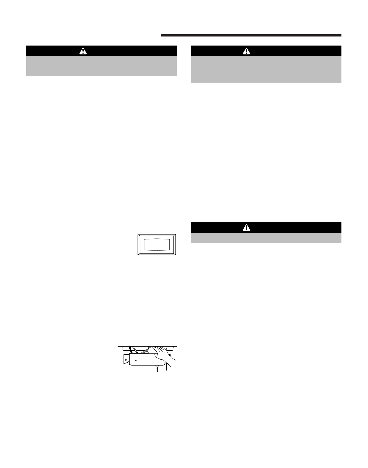
Operation
O
N
O
F
F
C
L
E
A
N
Setting The Controls (see page 13)
1. To start the normal ice making cycle, select ON.
2. To stop ice maker operation, select OFF.
NOTE: The CLEAN setting is used whenever solutions
are circulated through the ice maker for cleaning. See
the Care and Cleaning section (page 11).
IMPORTANT: If the water supply to the ice maker is
turned off, be sure to set the ice maker control to OFF.
How Your Icemaker Works
The ice maker will keep producing ice until the ice
maker’s bin is full and will restart automatically when
ice needs to be replenished in the bin.
Due to variables in installation and use, individual
results may vary. Room and water supply
temperatures affect the output of ice. Ice will also melt
away, especially at the start of an empty bin, but this
will slow down as ice accumulates.
NOTE: When using the ice maker for the first time,
discard at least the first two harvests of ice cubes.
Your ice maker is unique in forming ice. It uses
fractional freezing to form a slab of ice that is clear and
has less mineral content than the water it is produced
from. This is accomplished
by running water over the
cold evaporator plate
which gradually freezes
the water to produce the
ice slab. Mineral deposits
are left in the reservoir.
When the ice slab reaches
the correct thickness
determined by the
temperature of the
evaporator plate, the
electronic control switches
to the harvest cycle to
harvest the ice slab.
During the harvest cycle,
the ice slab falls from the
evaporator to the ice grid
cutter. Here, the ice slab is
3
cut into
⁄4" squares by the
grid cutter’s low voltage
heated wires. During the harvest cycle, the drain valve
will remain open for 45 seconds to drain the reservoir
of remaining deposits. After that, the water valve will
open for 2 minutes providing 2 quarts of water to the
reservoir for the next ice production cycle.
10
Care and Cleaning
CAUTION
•Avoid leaning on the cabinet door, you may bend
the door hinge or tip the ice maker.
Both the ice making system and the condenser need to
be cleaned regularly.
Cleaning the Ice Maker
System
Some impurities and minerals will remain and build-up
in the ice maker and stick to the ice maker’s parts over
time. This build-up must be removed for proper ice
production, ice quality, and ice maker life. Your ice
maker is equipped with a cleaning mode that will help
in cleaning out these impurities.
Clean the ice and water system at least annually to
remove buildup. Frequency of cleaning depends on
water hardness. With very hard water ( >14 gpg),
cleaning may be required as frequently as every
6 months.
To clean the ice maker:
C
O
L
1. Switch the selector switch to the
OFF position (see page 13).
2. Wait approximately 10 minutes for the ice to fall
into the storage bin. Remove all ice from the
storage bin.
3. Remove the drain plug at the bottom of the
reservoir to drain any remaining water and then
reinstall.
O
E
F
N
A
F
N
WARNING
• Read and follow manufacturer’s warnings on ice
machine cleaner products. Personal injury can
result when used improperly.
6. Replace front cover panel and close door.
7. Switch selector switch on the grill of the machine
to the CLEAN position. Three quarts of water will
automatically be added to ice maker cleaner.
8. The total cleaning time will end in approximately
49 minutes. The cleaning cycle will automatically
rinse the evaporator plate and also drain the
cleaning solution and rinse water.
9. After the cleaning cycle has ended, remove the
front cover panel again and check that build up
has been removed. The evaporator plate should be
clean, shiny, and smooth to the touch. If not and
build up is still visible, repeat the cleaning cycle
above. If build up is removed, continue below.
10. Disconnect power to the ice maker.
CAUTION
• Disconnect power to the ice maker for steps 11-14.
11. Remove the distributor tube, hose clamp, hose and
its rubber ends.
12. Thoroughly clean the inside of the distributor tube
and the spray holes. You can use the same
cleaning solution as before and an old tooth brush
to reach the inside of the distributor tube, rinse
thoroughly.
4. Unscrew and remove interior stainless steel front
cover panel to gain access to the reservoir.
5. Determine the amount of ice maker cleaner
needed, based on 3 quarts
of water (refer to the cleaner
manufacturer’s directions).
Pour this amount of ice
maker cleaner into the
reservoir of the ice maker.
Reservoir
Drain
Plug
NOTE: “Ice Maker Cleaner Appliance” by Vapco
Products, a Division of Garman Co., Inc. is
recommended. It is available from
www.vapcoproduct
s.com (1-800-466-5150) or
many refrigeration supply and hardware stores.
13. Reinstall the rubber end, hose, and hose clamp to
the distributor and then reinstall the distributor
tube to the evaporator with the spray holes pointed
to the bottom of the evaporator plate. Reinstall the
front cover panel.
14. Clean the ice maker’s interior, ice scoop, interior
door panel, and door gasket with mild detergent
and water. Using two tablespoons of baking soda
in one quart of warm water while cleaning will help
remove odors. Rinse with fresh water. DO NOT
USE ANY ABRASIVE CLEANING PRODUCTS.
Your ice maker is now clean and may be put back into
operation by reconnecting the power and switching the
selector switch to the ON position.
NOTE: Discard the first harvest of ice cubes produced
after the clean cycle has been run.
11
Care and Cleaning, cont.
CAUTION
• Disconnect power to the ice maker before cleaning.
Condenser
For best performance, brush or vacuum lint and dirt
from the condenser at least once a year. Unscrew the
grille on the bottom front of the cabinet to access the
condenser.
Ice Maker Cleaning Chart
EXTERIOR
Painted metal surfaces:
Cabinet, doors
Stainless steel doors
(certain models)
INTERIOR
Door gasket
Detergent and water
Mild liquid sprays
Light cleaning: mild
detergent and water
Moderate soil: Bon Ami*
Discoloration: Cameo
Stainless Steel Cleaner*
Baking soda and water
Detergent and water
Dry with a clean, soft cloth.
DO NOT wipe the ice maker with a soiled
dishwashing cloth or wet towel. These may leave
residue that can scratch and weaken the paint. Do
not use scouring pads, powdered cleansers, bleach
or cleaners containing bleach. These products can
scratch and erode the paint finish.
DO NOT wax plastic or vinyl parts.
Use a soft cloth or sponge.
Always wipe with the grain of the stainless steel.
DO NOT use chlorine bleach or any cleaning product
that contains chlorine bleach.
After cleaning, rinse and dry.
To restore luster and remove streaks follow with
Stainless Steel Magic Spray* (Jenn-Air model A912,
Part No. 20000008).
Use 1–2 tablespoons baking soda per quart of
water. Be sure to wring out excess water from
sponge or cloth when cleaning around controls,
lights or electrical parts.
Interior and door liner
* Brand names are the trademarks of the respective manufacturer.
12
Detergent and water
Baking soda and water
See above for baking soda solution.
DO NOT use abrasive cleaners, concentrated
detergents, bleaches, cleaning waxes, solvents or
polish cleaners to clean the ice maker interior.
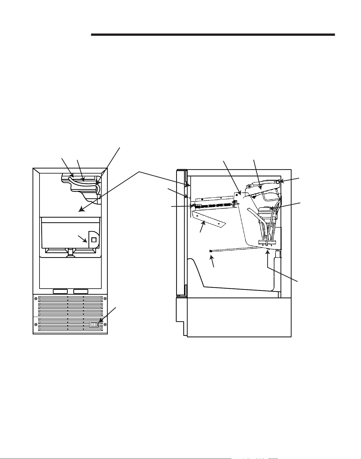
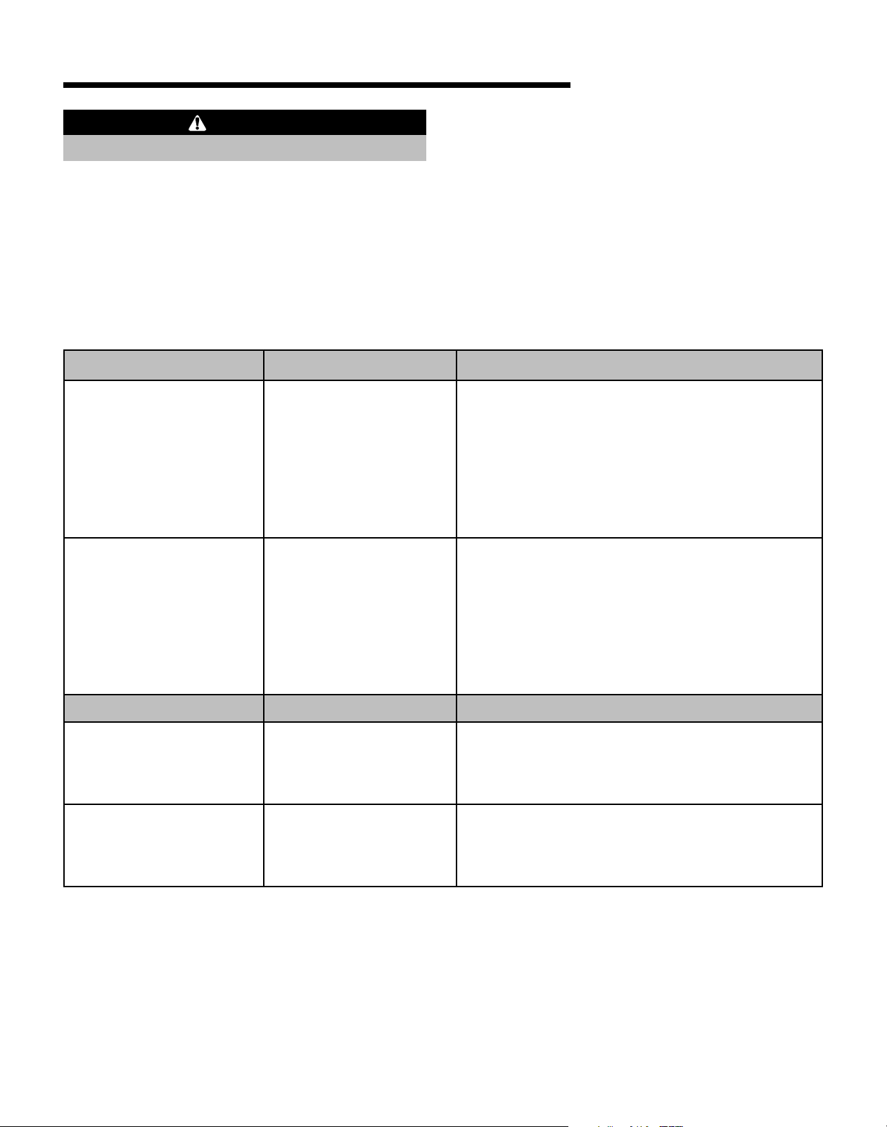
Before Calling for Service
Things to Remember
1. Allow your ice maker to run for at least 48 hours to
accumulate ice in ice maker’s bin.
2. The ice maker will cycle often between ice
production and ice harvest cycles.
3. Your ice maker will automatically shut down when
the ice bin is full.
Make sure that distributor
tubing is not in the path
of the ice slab.
Distributor Evaporator
Front Cover
Panel
Phillips
Screw
Grid Cutter
4. Disconnect power to the ice maker before working
on it.
5. Keep your ice maker clean for proper ice quality,
production, and unit life.
6. If ice maker is to be left unattended for a month or
longer, turn off its water supply, switch the control
to OFF and disconnect the power supply. Remove
any ice that remains in the bin.
EvaporatorReservoir
Distributor
Circulation
Pump
Ice Scoop
ON/OFF/CLEAN
Selector Switch
Front View Side View
Ice
Deflector
Bin
Thermostat
Reservoir
Drain
Plug
13
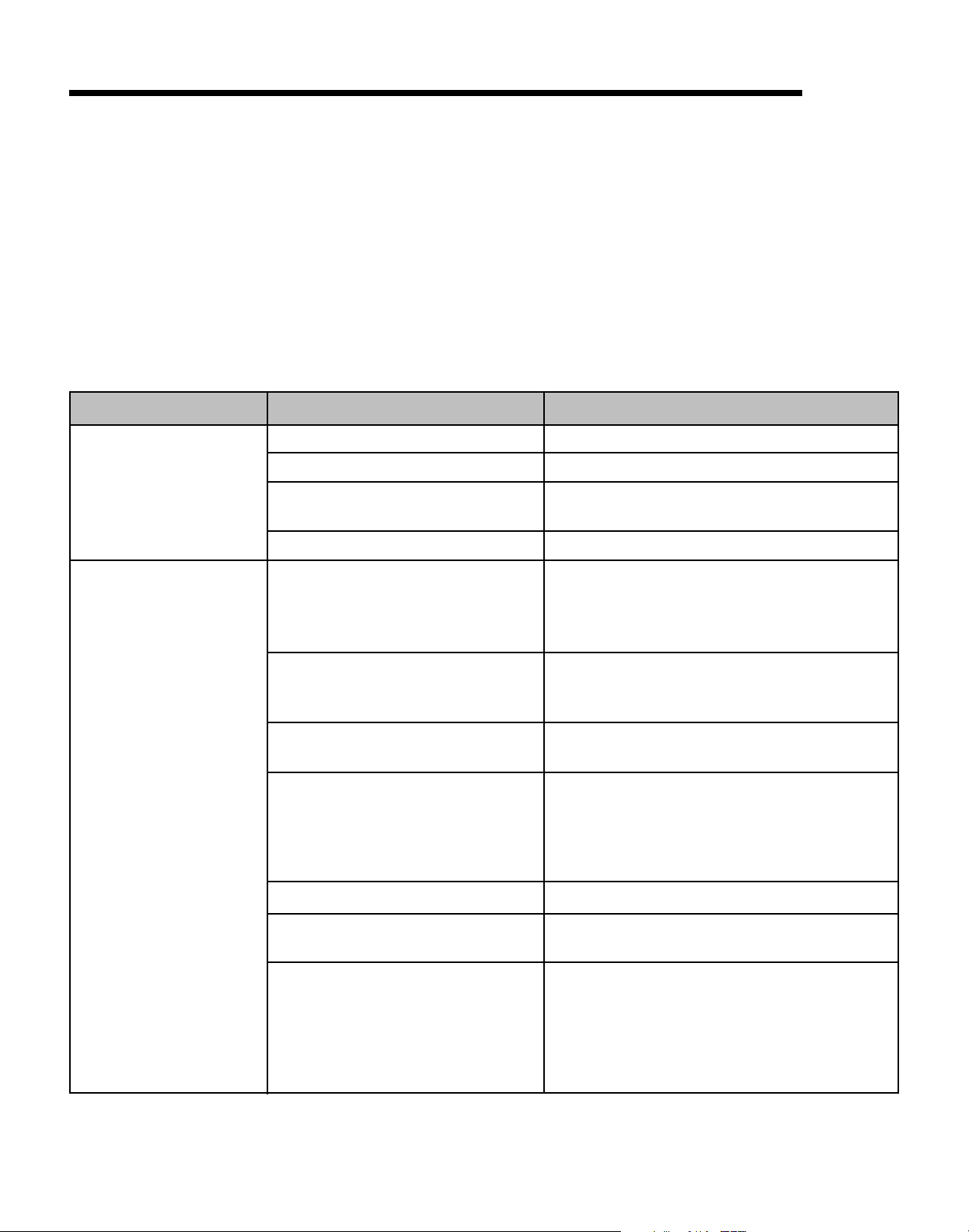
Before Calling for Service, cont.
Check the following items:
1. Make sure the ice maker is plugged into outlet.
2. Check the outlet for power. Test outlet with a lamp
to make certain outlet has power.
3. Make sure the ice maker’s selector switch is in the
ON position (see page 13).
4. Make sure that there is cold water supplied to the
ice maker.
5. Make sure drain plug on bottom of reservoir is
inserted.
PROBLEM
Ice maker does
not operate.
POSSIBLE CAUSE
The ice maker is unplugged.
Breaker is tripped or fuse is blown.
Ice machine selector switch is in
the OFF position.
Water supply is turned off.
6. Make certain unit is level from front to back and
side to side.
7. Make certain that the drain line to the ice maker is
not restricted or kinked.
If you are not able to correct the problem, contact your
dealer or the manufacturer. Be sure to have the model
number and the serial number handy before you call.
The model and the serial number are located on the
data plate inside on the lower front of the ice maker
cabinet.
SOLUTION
Plug in the ice maker.
Reset the breaker or replace fuse.
Set the rocker switch on the grille of the ice
machine to the ON position.
Turn on water supply to the ice maker.
Ice maker operates
but does not produce
any ice.
The ice maker has just been started
and it has been less than 6 hours.
Typical ice production cycle can
take up to 1
cycles can be longer.
The selector switch is in the OFF or
CLEAN position.
No water in the reservoir.
Distributor tube is restricted.
Build up of deposits on evaporator
plate.
Condenser fan air flow is restricted.
1
⁄2 hours. Initial startup
Ice produced when the unit is initially started
will melt off in the bin. In 6 hours there can be
a few cubes in the bin. This is normal
operation.
Check the unit in 24 hours for ice
accumulation in the bin.
Set the rocker switch on the grille of the ice
machine to the ON position.
Make sure that the reservoir drain plug is
installed. Check the water line to make sure it
is on and that there are no restrictions or
kinks. Check all filters to make sure they are
not restricted or plugged.
See Cleaning the Ice Maker System (page 11).
See Cleaning the Ice Maker System (page 11).
Make certain the grille in the front of the unit
is free and open for proper air circulation.
Check and clean the condenser coil by
removing the grille in the front of the unit.
Clean the condenser with a vacuum and brush
attachment.
14

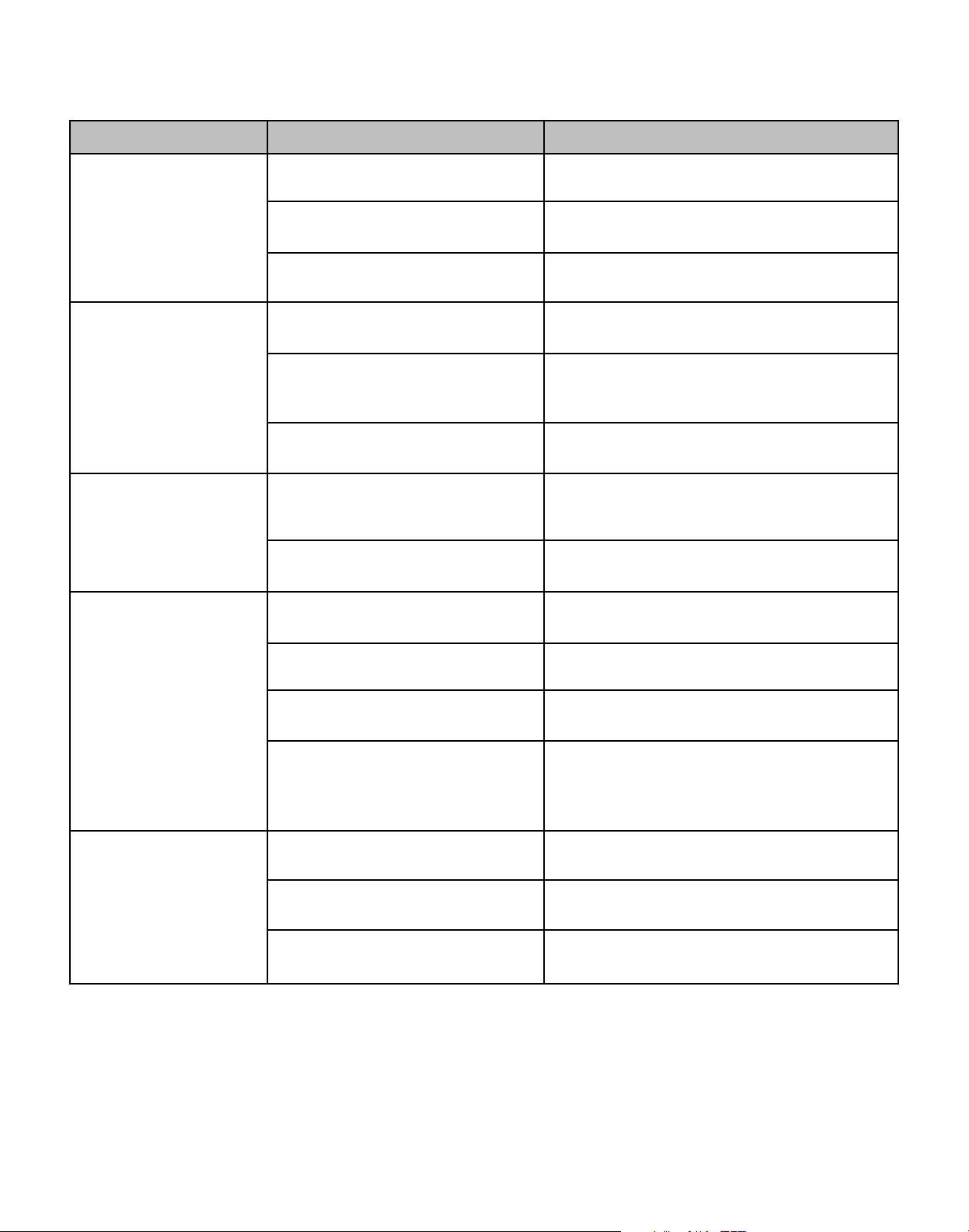
PROBLEM
POSSIBLE CAUSE
SOLUTION
Ice maker operates
but does not produce
any ice, cont.
Ice cubes are too
small (less than
1
⁄2" thick).
Room and/or water temperature is
too warm.
Leaking drain valve.
Inadequate drain system.
Grid cutter is unplugged.
Low ice consumption.
Move the ice maker to an area where ambient
temperature is below 80° F. The ice maker
should not be placed next to a heat source such
as an oven. Check for cold water connection.
See Cleaning the Ice Maker System (page 11).
This will also dissolve and flush out foreign
material in the drain valve which may be causing
it to leak.
Restriction in drain lines will cause ice in the
bin to melt. If using a gravity drain, make
certain there are no kinks or restrictions in the
drain lines. If using a drain pump, check the
inlet screen, discharge line, and vent line for
any buildup or restrictions.
Remove the front cover panel and plug the
grid cutter into the receptacle on the side of
the liner.
Ice is slowly melting on the ice bin and will
affect the size of the ice cube. This is normal
operation. When the ice bin needs to be
replenished, cubes will return to regular size.
Not enough water in reservoir.
Distributor tube is restricted.
Build up of deposits on evaporator
plate.
Inadequate drain system.
Leaking drain valve.
Room temperature is too warm.
Make sure that the reservoir drain plug is
installed properly. Check the water line to the
ice maker to make sure there are no
restrictions or kinks. Check all filters to make
sure they are not restricted or plugged.
See Cleaning the Ice Maker System (page 11).
See Cleaning the Ice Maker System (page 11).
Restriction in drain lines will cause ice in the
bin to melt to a thinner cube. If using a gravity
drain, make certain there are no kinks or
restrictions in the drain lines. If using a drain
pump, check the inlet screen, discharge line,
and vent line for any build or restrictions.
See Cleaning the Ice Maker System (page 11).
This will also dissolve and flush out foreign
material in the drain valve which may be
causing it to leak.
Move to an area where temperature is below
80° F.
15

Before Calling for Service, cont.
PROBLEM
Ice cubes are too big
(greater than
Hollow ice slab.
Ice is not clear.
3
⁄4" thick).
POSSIBLE CAUSE
Ice slab not releasing.
Condenser fan air flow is restricted.
Room temperature is too warm.
Distributor tube is restricted.
Build up of deposits on evaporator
plate.
Low water level in reservoir.
Low water level in reservoir.
SOLUTION
See Cleaning the Ice Maker System (page 11).
Make certain the grille in the front of the unit is
free and open for proper air circulation. Check
and clean the condenser coil by removing the
grille in the front of the unit. Clean the condenser
with a vacuum and brush attachment.
Move to an area where temperature is below 80° F.
See Cleaning the Ice Maker System (page 11).
See Cleaning the Ice Maker System (page 11).
Make sure that the reservoir drain plug is
installed properly. Check the water line to the
unit to make sure there are no restrictions or
kinks in the line. Check all filters to make sure
they are not restricted or plugged.
Make sure that the reservoir drain plug is
installed properly. Check the water line to the
ice maker to make sure there are no restrictions
or kinks in the line. Check all filters to make
sure they are not restricted or plugged.
Low ice production.
Unit is running, has
run over a 48 hour
period, and there is
little ice in bin.
Softened water supply.
Room temperature is too cold.
Low water level in reservoir.
Distributor tube is restricted.
Build up of deposits on evaporator
plate.
Inadequate drain system.
Condenser fan air flow is restricted.
Make certain that water line is not connected
to the water softener.
Move the ice maker to an area where room
temperature is above 55° F.
Make sure that the reservoir drain plug is
installed properly. Check the water line to the
ice maker to make sure there are no
restrictions or kinks. Check all filters to make
sure they are not restricted or plugged.
See Cleaning the Ice Maker System (page 11).
See Cleaning the Ice Maker System (page 11).
Restriction in drain lines will cause ice in the
bin to melt. If using a gravity drain, make
certain there are no kinks or restrictions in the
drain lines. If using a drain pump, check the
inlet screen, discharge line, and vent line for
any buildup or restrictions.
Make certain the grille in the front is free and
open for proper air circulation. Check and
clean the condenser coil by removing the grille
in the front. Clean the condenser with a
vacuum and brush attachment.
16
PROBLEM
POSSIBLE CAUSE
SOLUTION
Unit continues to run
and produce ice.
Grid cutter is not
cutting the ice slab.
Ice cubes are sticking
together.
Ice level is too high.
Ice bin is not full.
Room temperature is too warm.
Ice maker is not level.
The selector switch is not in the ON
position.
The grid cutter is not plugged into
the receptacle.
Time to cut through the slab.
Ice consumption is low.
Room temperature is too warm.
The ice machine is not level.
The ice maker will automatically shut down
when ice reaches the thermostat.
Move the ice maker to an area where room
temperature is below 80° F.
Use a level to check the unit for level from
side to side and front to rear.
Set the rocker switch on the grille of the ice
machine to the ON position.
Remove the front cover panel and plug the
grid cutter into the receptacle on the side of
the liner.
It can take up to 35 minutes to cut through a
harvested ice slab. This is normal operation.
Use the ice in the bin frequently. Ice will stick
together if left in insulated bin over long
periods of time.
Move the ice maker to an area where
temperature is below 80° F.
Use a level to check the ice maker for level
from side to side and front to rear.
Ice level is too low.
Room temperature is too warm.
Ice deflector is not in place or
secured properly.
Bin level thermostat needs
adjusted.
The ice machine is not level.
Room temperature is too cold.
The selector switch is not in the ON
position.
Move the ice maker to an area where
temperature is below 80° F.
Check to see that the ice deflector is in place
and secured below the grid cutter.
You can adjust the bin thermostat tube by
simply pressing directly down on the tube 5"
from the front of the tube to get a desired bin
level.
Use a level to check the unit for level from
side to side and front to rear.
Move the unit to an area where temperature is
above 55° F.
Set the rocker switch on the grille of the ice
machine to the ON position (see page 13).
17
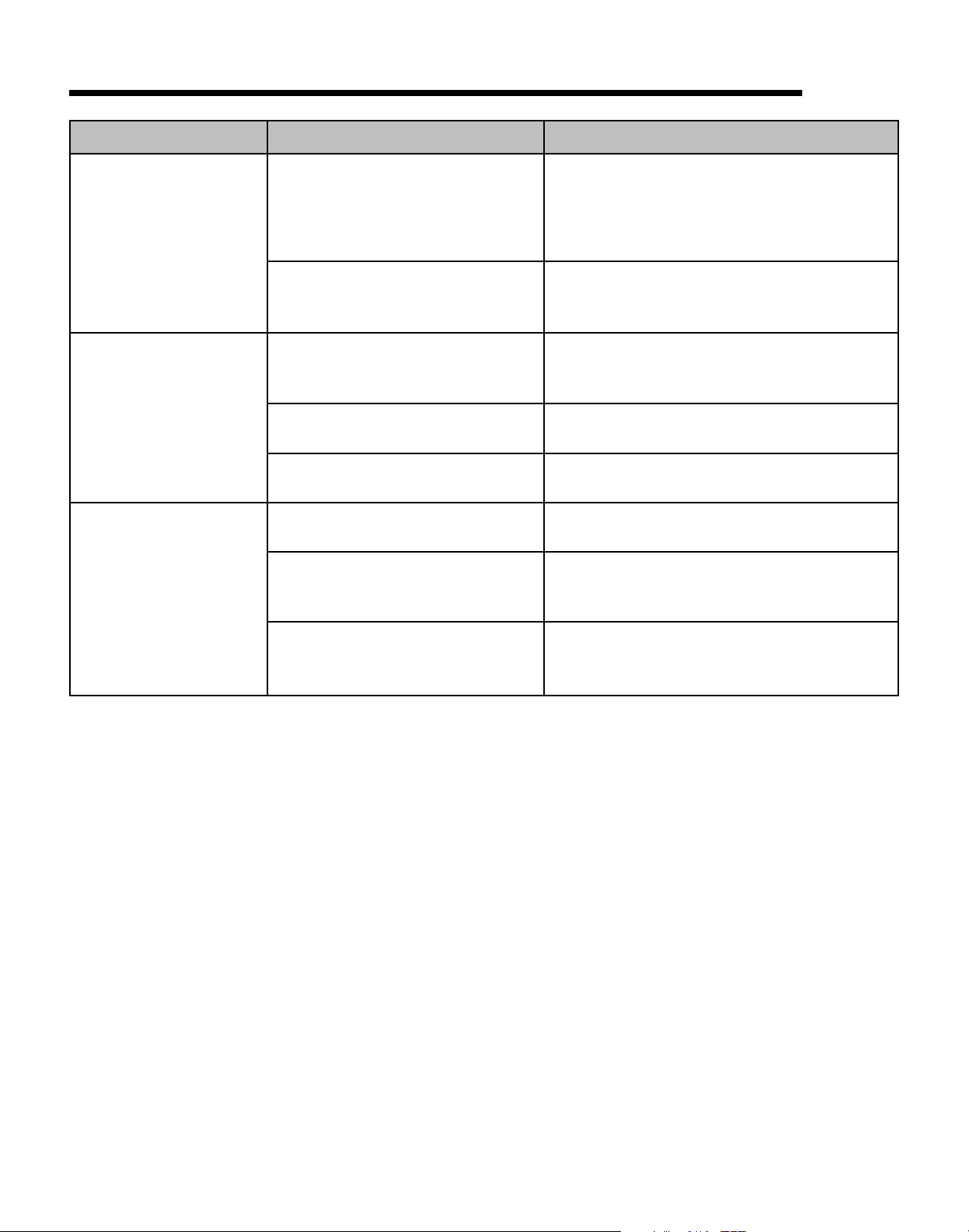
Before Calling for Service, cont.
PROBLEM
Water keeps backing
up into the ice bin
(gravity drain).
Water keeps backing
up into the ice bin
(drain pump).
The drain pump cycles
on and off erratically.
POSSIBLE CAUSE
Inadequate drain system.
Foreign material in ice bin drain.
Drain pump tubing kinked or
restricted.
Inlet screen to the drain pump is
restricted or blocked.
Drain pump and/or the ice machine
are not level.
Vent line to the drain pump is
restricted or kinked.
Discharge line is restricted or
kinked.
SOLUTION
Restriction or improperly installed drain lines
will cause water to back up into the ice bin.
Make certain there are no kinks or restrictions
in the drain lines. If necessary, consult a
qualified plumber.
Foreign material is restricting or blocking the
ice bin drain located at the right rear corner of
the ice bin. The drain will need to be cleared.
Check inlet, discharge, and vent line tubing for
any kinks or restrictions and repair as
necessary.
Clean the inlet screen to the drain pump.
Check and level is necessary the drain pump
as well as the ice machine.
Check the vent line for any restrictions or
kinks and repair as necessary.
Check the discharge line and connection to
the desired drain for any restrictions or kinks
and repair as necessary.
The drain pump is not level.
The drain pump must be level. Check for level
on the top of the drain pump case and adjust
the tubing or use shims to level.
18
 Loading...