

Jenn-Air JGD8348CDP, JGC8645BDB/Q/S/W, JGCP430CDP, JGCP636CDP, JGCP648CDP Service Manual
...
Service
This manual is to be used by qualified appliance
technicians only. Maytag does not assume any
responsibility for property damage or personal
injury for improper service procedures done by
an unqualified person.
Gas Cooktops
This Base Manual covers general information
Refer to individual Technical Sheet
for information on specific models
This manual includes, but is
not limited to the following:
JGD8348CDP
JGC8430BDB/Q/S/W
JGC8645BDB/Q/S/W
JGCP430CDP
JGCP636CDP
JGCP648CDP
16023565
November 2004
©2004 Maytag Services
Important Information
Pride and workmanship go into every product to provide our customers with quality products. It is possible, however,
that during its lifetime a product may require service. Products should be serviced only by a qualified service
technician who is familiar with the safety procedures required in the repair and who is equipped with the proper tools,
parts, testing instruments and the appropriate service information. IT IS THE TECHNICIANS RESPONSIBILITY TO
REVIEW ALL APPROPRIATE SERVICE INFORMATION BEFORE BEGINNING REPAIRS.
Important Notices for Servicers and Consumers
!
To avoid risk of severe personal injury or death, disconnect power before working/servicing on appliance to avoid
electrical shock.
To locate an authorized servicer, please consult your telephone book or the dealer from whom you purchased this
product. For further assistance, please contact:
WARNING
Customer Service Support Center
CAIR Center
Web Site Telephone Number
WWW.JENNAIR.COM ............................................. 1-800-536-6247
CAIR Center in Canada ........................................... 1-800-688-2002
Recognize Safety Symbols, Words, and Labels
DANGER!
DANGER—Immediate hazards which WILL result in severe personal injury or death.
WARNING!
WARNING—Hazards or unsafe practices which COULD result in severe personal injury or death.
CAUTION!
CAUTION—Hazards or unsafe practices which COULD result in minor personal injury, product or property
damage.
2 16023565 ©2004 Maytag Services

Table of Contents
Important Information .................................................. 2
Safety Information ....................................................... 4
Safety Practices for Servicer .................................. 5
Servicing ................................................................ 5
Before Installing ..................................................... 5
Receiving Cooktop ................................................. 5
Unpacking .............................................................. 5
Gas Connection ..................................................... 6
Electrical Requirements ......................................... 6
Electrical Connections ........................................... 6
Product Safety Devices .......................................... 7
General Information
Model Identification Rating Label and Ordering
Relacement Parts .................................................. 8
Cooking Nomenclature ................................................ 8
Specifications ........................................................ 9
Placement of the Cooktop ...................................... 9
Do Not Block Air Vents .......................................... 9
Location of Model Number ...................................... 9
Model Identification ................................................ 9
Service ................................................................... 9
Parts and Accessories ........................................... 9
Extended Service Plan ........................................... 9
Grounding .............................................................. 9
Cooktop Description ............................................. 10
Troubleshooting Procedures ..................................... 11
Component Testing Information ................................. 13
Disassembly Procedures
Disassembly Procedures for Models Listed ........... 16
JGC8430BDB/W/Q/S
JGC8645BDS
Main Top Removal ................................................ 16
Spark Module Removal Bottom Access ............... 16
Spark Module Removal ........................................ 16
Surface Ignitor Removal ........................................ 16
Burner Switch Removal ........................................ 16
Manifold Pipe Removal ......................................... 16
Orifice Holder Removal ......................................... 16
Burner Tubing Removal ........................................ 16
Disassembly Procedures for Models Listed ........... 18
JGD8348CDP
JGCP430ADP
JGCP636ADP
JGCP648ADP
Main Top Removal ................................................ 18
Spark Module Removal ........................................ 18
Surface Ignitor Removal ........................................ 18
Burner Switch Removal ........................................ 18
Manifold Pipe Removal ......................................... 18
Orifice Holder Removal ......................................... 18
Burner Tubing Removal ........................................ 18
E-Burner Removal ................................................ 18
Grease Filter Removal .......................................... 20
Blower Removal ................................................... 20
Appendix A: Installation Instructions
Models JGCP430ADP, JGCP636ADP,
JGCP648ADP .................................................... A–2
Model JGD8348CDP .... ...................................... A–4
Ducting Instructions, Model JGD8348CDP ......... A–6
Model JGC8430BD* ........................................... A–9
Model JGC8645BDS ........................................ A–10
Appendix B: Use and Care
Models JGCP430ADP, JGCP636ADP,
JGCP648ADP ....................................................
Model JGD8348CDP .... ...................................... B–4
Model JGC8430BD* ........................................... B–6
Model JGC8645BDS ...... .................................... B–8
Care and Cleaning ............................................ B–10
Appendix C: LP/Natural Gas Conversion
Models JGD8348CDP, JGCP430ADP,
JGCP636ADP, JGCP648ADP ............................ C–2
Models JGD8430BD*, JGD8645BDS .................. C–4
B–2
©2004 Maytag Services 16023565 3
Safety Information
As with all appliances, there are certain rules to follow for
safe operation. Verify everyone who operates the cooktop
is familiar with the operations and with these precautions.
Use appliance only for its intended purpose as described.
Pay close attention to the safety sections of this manual.
Recognize the safety section by looking for the following
symbol or the word safety.
Recognize this symbol as a safety precaution.
!
WARNI NG
!
This gas appliance contains or produces a chemical or
chemicals which are known to the state of California to
cause cancer, birth defects or other reproductive harm.
To reduce the risk from substances in the fuel or from
fuel combustion make sure this appliance is installed,
operated, and maintained according to the instructions
in this manual.
Due to the nature of cooking, fires can occur as a
result of overcooking or excessive grease. Although a
fire is unlikely, if one occurs proceed as follows:
WARNI NG
!
If the information in this manual is not followed exactly,
a fire or explosion may result causing property
damage, personal injury or death.
Do not store or use gasoline or other flammable vapors
and liquids in the vicinity of this or any other appliance.
WHAT TO DO IF YOU SMELL GAS
• Extinguish any open flame.
• Do not try to light any appliance.
• Do not touch any electrical switch; do not use any
phone in your building.
• Immediately call your gas supplier from a neighbor’s
phone. Follow the gas supplier’s instructions.
• If you cannot reach your gas supplier, call fire
department.
Installation and service must be performed by an
authorized installer, service agency or gas supplier.
Cooktop Fires
1. Do not turn on any ventilation system above the
cooktop.
2. Turn all controls to the OFF position.
3. As an added precaution turn off the electricity at
the main circuit breaker or fuse box and the gas
at the main supply valve.
4. Cover the food or grease to smother fire.
If smoke or fire persist call the local fire department.
To avoid the risk of property damage or personal injury
do not obstruct the flow of combustion or ventilation air.
To avoid the risk of electrical shock, serious personal
injury or death: Make sure your cooktop has been
properly grounded and always disconnect the electrical
supply before servicing the unit.
NOTE: The maximum gas supply pressure for these
models must not exceed 14 inches W.C.P.
!
WARNI NG
To avoid risk of electrical shock, property damage,
personal injury or death; verify wiring is correct, if
components were replaced. Verify proper and complete
operation of unit after servicing.
4 16023565 ©2004 Maytag Services
Safety Information
Safety Practices for Servicer
Safe and satisfactory operation of gas cooktops depend
upon its design and proper installation. However, there is
one more area of safety to be considered:
Servicing
Listed below are some general precautions and safety
practices which should be followed in order to protect the
service technician and consumer during service and after
service has been completed.
1. Gas smell—Extinguish any and all open flames and
open windows.
2. Turn gas off—Service cooktop with gas turned off
unless testing requires it.
3. Checking for gas leaks—Never check for leaks with
any kind of open flame. Soap and water solution
should be used for this purpose. Apply solution to
suspected area and watch for air bubbles which
indicates a leak. Correct leaks by tightening fittings,
screws, connections, applying approved compound,
or installing new parts.
4. Using lights—Use a hand flashlight when servicing
cooktops or checking for gas leaks. Electric
switches should not be operated where leaks are
suspected. This will avoid creating arcing or sparks
which could ignite the gas. If electric lights are
already turned on, they should not be turned off.
5. Do not smoke—Never smoke while servicing gas
cooktops, especially when working on piping that
contains or has contained gas.
6. Check cooktop when service is completed—After
servicing, make visual checks on electrical
connection, and check for gas leaks. Inform
consumer of the condition of cooktop before leaving.
7. Adhere to all local regulations and codes when
performing service.
Before Installing
Installing the gas cooktop in compliance with local
electrical and gas building codes results in proper
operation and consumer satisfaction with the cooktop.
Receiving Cooktop
Inspect cooktop thoroughly at time of delivery.
Immediately report any visible damage to carrier. Damage
not discovered until after accepting delivery can still be
claimed by using a concealed damage report form,
available from the carrier's agent.
All shipments, i.e., complete cooktop or parts, are
shipped at the buyer's risk. Maytag's responsibility ends
when the consignment is accepted by the carrier in
"good order." Maytag supports damage claims by
supplying invoices, bills of laden, and other
documentation as needed. providing this assistance,
however, does not imply any responsibility for settling
claims. Do not deduct claims for loss or damage from the
invoice and do not withhold payment pending adjustment
of claims. Do not return any units or parts for credit
without written consent.
Unpacking
• Open the carton and slide cooktop out of packing.
• Remove all literature packed with the cooktop and
place cooktop onto a protective flat surface.
• Avoid countertop damage by NOT sliding cooktop
across the countertop.
• Remove grates, burner caps, and pressure regulator
from the carton.
!
WARNI NG
Do not store items of interest to children in cabinets
above cooktop. Children may climb on cooktop to
reach these items and become seriously injured.
©2004 Maytag Services 16023565 5

Safety Information
Gas Connection
Verify the cooktop installation meets local codes or
current American Gas Association (CGA) requirements in
the absence of local codes. When installing CGA units,
verify that installation meets local codes or in absence of
local codes, current Natural Gas Installation Code CAN/
CGA-B149.1 or current Propane Installation Code, CAN/
CGA-B149.2 before connecting to the gas supply
system.
Installation in manufactured homes must conform with
the standard CAN/CSA-Z240 Mobile Homes,
Manufactured Home Construction and Safety Standards,
Title 24CFR, Part 3280, or with local codes is applicable.
WARNI NG
!
To avoid risk of personal injury or property damage.
Use only new flexible connectors design certified by
AGA or CGA. Do not reuse an old connector. Do not
reuse an old connector when moving the appliance.
Access to Gas Connection
Install manual shut-off valve in an accessible location
outside the cooktop. Be aware of the location of the
shut-off valve. Shut-off valve is not supplied with the
cooktop.
Use a pipe joint compound resistant to the action of
propane gas on all male threads.
Connect the gas supply line either using hard piping or a
properly-certified flexible connector. The pressure
regulator supplied with cooktops have a 1/2 inch NPT
female connection. Check local codes before choosing a
method.
Electrical Requirements
120-volt, 60 Hertz, 20 amp, individual circuit which is
properly grounded, polarized and protected by a circuit
breaker or fuse.
Electrical Connections
Models with automatic pilotless (spark) ignition require
an external electrical source that must be grounded and
polarized in accordance with local codes. use National
Electrical Code, ANSI/NFPA No. 70-Latest Edition in the
absence of local codes.
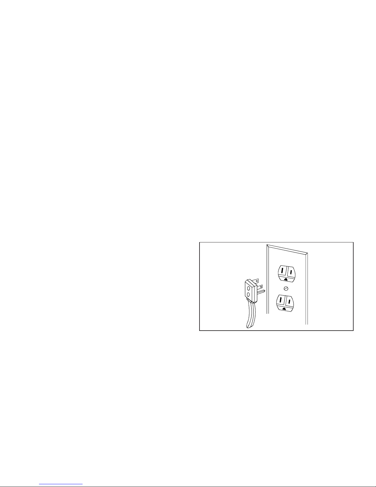
The wall receptacle must be placed within easy reach of
the power cord without interfering with the gas supply line
Cooktops must be properly grounded. Cooktop power
cords are equipped with a three-prong ground plug. They
fit standard three-prong wall receptacles.
WARNI NG
!
To avoid risk of electrical shock or property damage.
Do not cut or remove the third (ground) prong from the
power cord.
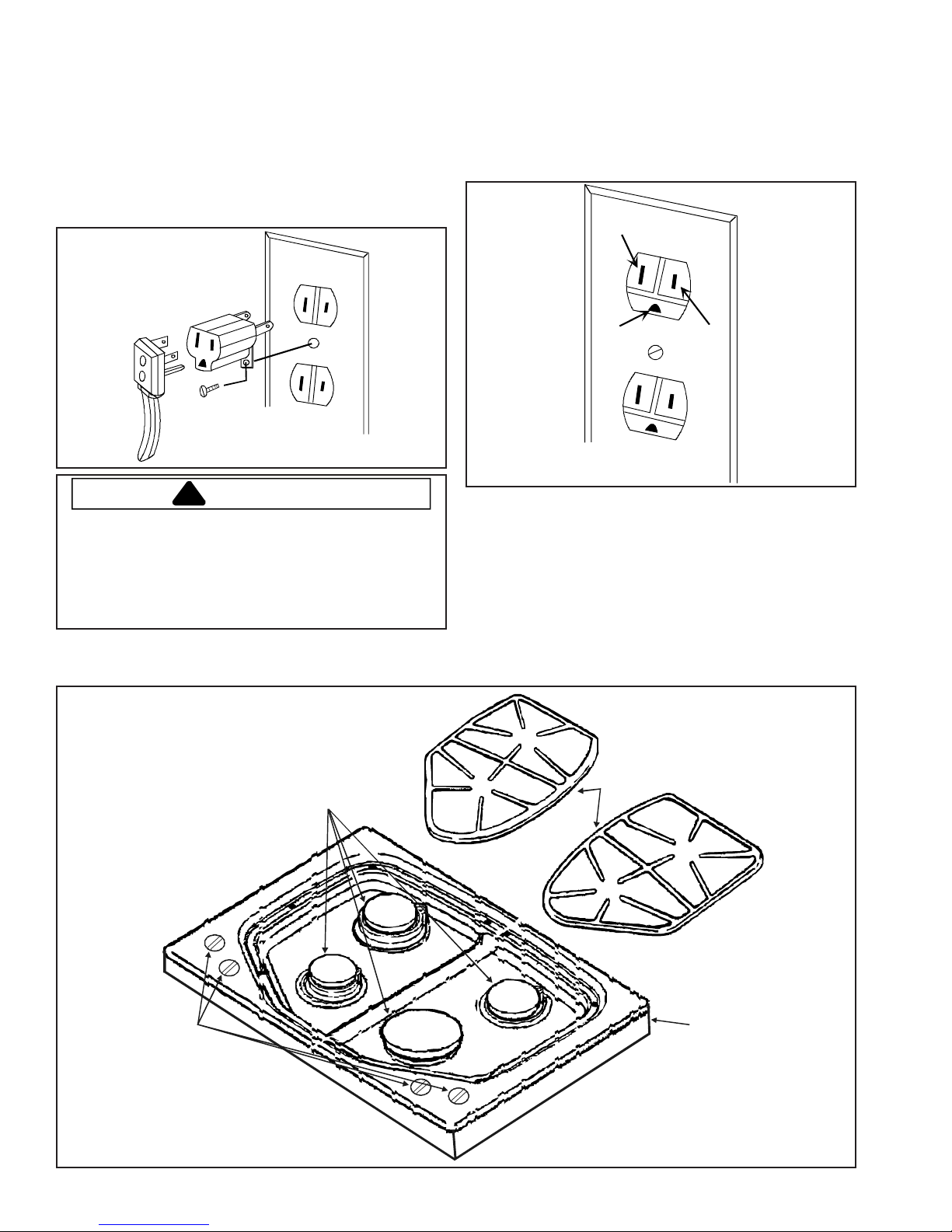
The consumer is responsible for replacing any standard
two-prong wall receptacle with a grounded and polarized
three-prong wall receptacle. A qualified electrician should
check any receptacle the customer doubts is properly
grounded. The wiring diagram is on the bottom of the
cooktop.
WARNI NG
!
Do not over tighten the fitting on the pressure regulator.
Overtightening may crack the regulator.
6 16023565 ©2004 Maytag Services

Safety Information
Product Safety Devices
Safety devices and features have been engineered into the product to protect consumer and servicer. Safety devices
must never be removed, bypassed, or altered in such a manner as to defeat the purpose for which they were intended.
Listed below are various safety devices together with the reason each device is incorporated in the gas ranges.
Pressure Regulator Maintains proper and steady gas pressure for operation of oven controls. Regulator
must be set for the type of gas being used Natural or LP. After servicing regulator,
make certain it is set properly before completing service.
Gas Burner Orifices Universal orifices are used on most valves. They must be adjusted or set for the type
of gas being used Natural
After servicing a valve or orifice verify it is adjusted properly before completing service.
Grounded Cooktop Frame Ground prong on power cord is connected to the frame, usually a green lead fastened
by a screw. In addition, any part or component capable of conducting an electric
current is grounded by its mounting.
If any ground wire, screw, strap, nut, etc. is removed for service, or any reason, it
must be reconnected to its original position with original fastener before the appliance
is put into operation again.
Failure to do so can create a possible shock hazard.
or LP.
©2004 Maytag Services 16023565 7
General Information
This manual provides basic instructions and suggestions
for handling, installing and servicing gas cooktops.
The directions, information, and warnings in this manual
are developed from experience with, and careful testing of
the product. If the unit is installed according to this
manual, it will operate properly and will require minimal
servicing. A unit in proper operating order ensures the
consumer all the benefits provided by clean, modern gas
Model Identification Rating Label and
Ordering Replacement Parts
Model numbers are recorded on the rating label. Rating
label is located on the bottom of the burner box. Before
ordering parts, write down the correct model and serial
number from rating label. This avoids incorrect
shipments and delays. Please refer to parts reference
material when ordering replacement parts.
cooking.
This manual contains information needed by authorized
service technicians to install and service gas cooktops.
There may be, however, some parts which need further
explanation. Refer to the Technical Sheets or toll-free
technical support line to recieve technical assistance
from authorized service technicians.
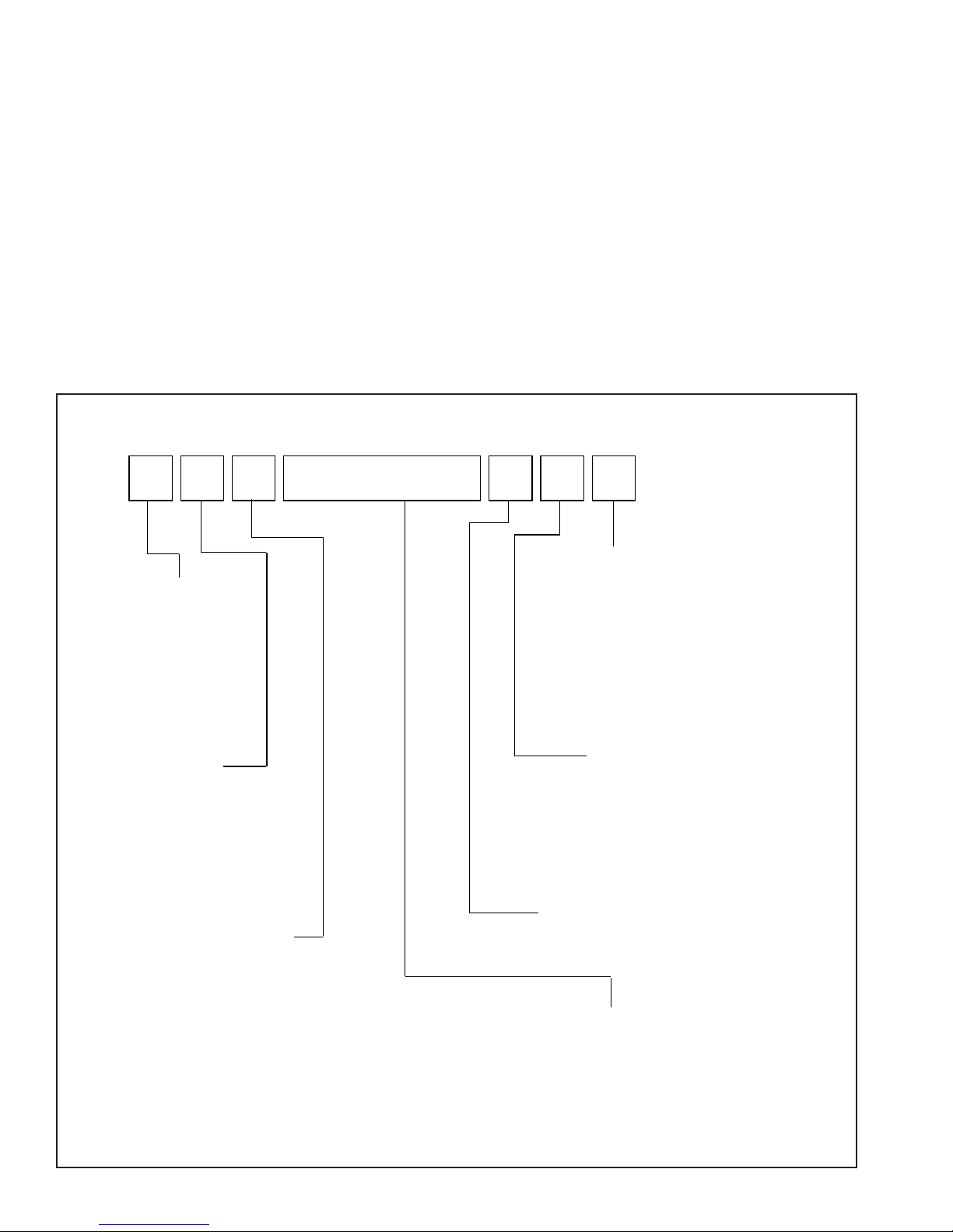
Cooking Nomenclature
J G C 8 4 3 0 B D W
A Almond on Almond
Brand
A Amana
C Magic Chef
G Graffer &
Sattler
H Hardwick
J Jenn-Air
M Maytag
N Norge
U Universal
Y Cro sley
Fuel
B Butane
D Dual Fuel
E/J Electric
G Gas, Natural
L Liquid Propane
M Microwave
P Standing Pilot
X No Fuel
W Warming Drawer
Product Type
A Accessory/Cartridge
C Cooktop Updraft/Countertop
D Downdraft Cooktop or Warming Drawer
E Eyelevel Range
G Grill
L Range (20")
M Range (36")
P Drop In (24")
Q Wall Oven (27")
R Range, Free-Standing (30")
S Slide-In (30")
T Range Hood
V OTR
W Wall Oven
Y RV Range
Z RV Top
B Black
C Brushed Chrome
H Traditional White
L Traditional Almond
P Prostyle
Q Monochromatic Bisque
S Stainless
T Traditional Bisque
W White on White
F Frost White (True Color White)
N Natural Bisque (True Color Bisque)
A UL/AGA
C CSA/CGA/CUL
D Dual Listed
G 220-240 V / 50-60 Hz
M Military Model
P PSB Approved
X Export 120 V / 60 Hz
Production Code
This identifies the
production version.
Feature Content
1000-3999 Brands
4000-6999 Maytag/Amana
7000-9999 Jenn Air
8 16023565 ©2004 Maytag Services
Color
Listing
(Singapore)
General Information
Specifications
Refer to individual Technical Sheet for specification
information.
Placement of the Cooktop
This cooktop must be placed in the kitchen or
comparable room. All safety guidelines must be followed
and free air flow around the cooktop is essential.
Do Not Block Air Vents
All air vents must be kept clear during cooking. If air
vents are covered during operation, the oven may
overheat. If this occurs, a sensitive, thermal safety
device automatically removes power to the oven,
rendering the oven inoperable. The oven will remain in
this state until it has sufficiently cooled.
Location of Model Number
To request service information or replacement parts, the
service center will require the complete model, serial, and
manufacturing number of your cooktop. The number can
be found in the burner box. Lift the cooktop surface to
view the data.
Model Identification
Complete enclosed registration card and promptly return.
If registration card is missing:
• For Jenn-Air product call 1-800-536-6247 or visit the
Web Site at www.jennair.com
• For product in Canada call 1-866-587-2002 or visit the
Web Site at www.jennair.com
When contacting provide product information located on
rating plate. Record the following:
Model Number: ___________________
Manufacturing Number: ___________________
Serial or S/N Number: ___________________
Date of purchase: ___________________
Dealer’s name and address: ___________________
Service
Keep a copy of sales receipt for future reference or in
case warranty service is required. To locate an authorized
servicer:
• For Jenn-Air product call 1-800-688-1100 or visit the
Web Site at www.jennair.com
• For product in Canada call 1-866-587-2002 or visit the
Web Site at www.jennair.com
Warranty service must be performed by an authorized
servicer. We also recommend contacting an authorized
servicer, if service is required after warranty expires.
Parts and Accessories
Purchase replacement parts and accessories over the
phone. To order accessories for your product call:
• For Jenn-Air product call 1-800-688-1100 or visit the
Web Site at www.jennair.com
• For product in Canada call 1-866-587-2002 or visit the
Web Site at www.jennair.com
Extended Service Plan
We offer long-term service protection for this new oven.
• Dependability Plus
specially designed to supplement Jenn-Air’s strong
warranty. This plan covers parts, labor, and travel
charges.
Call 1-800-925-2020 for information.
SM
Extended Service Plan is
Grounding
NOTE: This appliance must be properly grounded, for
personal safety.
Power cord on this appliance is equipped with a threeprong grounding plug. This matches standard three-prong
grounding wall receptacle to prevent possibility of electric
shock from this appliance.
Consumer should have wall receptacle and circuit
checked by qualified electrician to verify receptacle is
properly grounded.
Where standard two-prong wall receptacle is
encountered, it is consumers responsibility and
obligation to have it replaced with a properly grounded
three-prong wall receptacle.
DO NOT, UNDER ANY CIRCUMSTANCES, CUT OR
REMOVE THE THIRD (GROUND) PRONG FROM
POWER CORD.
©2004 Maytag Services 16023565 9
General Information
For 15 amp circuits only. Do not use an adapter on 20
amp. circuit. Where local codes permit, a TEMPORARY
CONNECTION may be made to properly grounded twoprong wall receptacle by the use of a UL listed adapter
available at most hardware stores.
Larger slot on adapter must be aligned with larger slot in
the wall receptacle to provide proper polarity.
WARNI NG
!
Attaching adapter ground terminal to wall receptacle
cover screw does not ground appliance unless the
cover screw is metal and not insulated, and wall
receptacle is grounded through the house wiring.
Consumer should have circuit checked by a qualified
electrician to verify receptacle is properly grounded.
When disconnecting power cord from adapter, always
hold adapter with one hand. If this is not done, adapter
ground terminal is very likely to break with repeated use.
Should this happen, DO NOT USE appliance until a
proper ground has been established.
Neutral Wire
Ground
NOTE: Circuit tester can be use to verify voltage is
present at the outlet, connect one lead to hot
line and the other lead to ground, circuit tester
should light.
Hot Line
Cooktop Description
Burner
Knobs
Burner Caps
and
Assemblies
Grates
Main
To p
10 16023565 ©2004 Maytag Services
Troubleshooting Procedures
!
To avoid risk of electrical shock, personal injury or death; disconnect power and gas to cooktop before servicing,
unless testing requires power and/or gas.
!
• Verify proper grounding before checking for trouble.
• Be careful of any high voltage circuit.
• Do not touch any part of the circuit on the printed circuit board, since static electric discharge may damage the
control panel. Always touch ground while working on this panel to discharge the static electricity, which may be
resting on your body.
WARNING
CAUTION
Problem Possible Cause Correction
Burners will not ignite; no
spark at top burner.
Burner will not ignite. No
spark to burner ignitors when
burner knob is rotated to
“LITE” position.
No spark or only random
spark at one ignitor.
Unit continues to spark after
knob is turned to OFF
position.
Poor ground on burner cap .........................
Weak or failed spark module ......................
Low gas pressure ........................................
No 120 VAC to range ..................................
Micro switch contacts not closing ................
Faulty wiring. Bad connection at burner
electrode and electrode socket ...................
Inoperative spark module ............................
Electrode dirty. Burner cap dirty ..................
Cracked or broken electrode, electrode
wire or electrode socket ..............................
Check for cracked ignitor or pinched
ignitor wire ..................................................
Poor continuity to burner cap.......................
Bad ground connection or lack of
continuity to ground or ignitor ......................
Cracked or broken ignitor extension lead....
Shorted valve switch/harness......................
Switch has slipped off the valve ..................
• Clean burner cap.
• Replace spark module.
• Verify pressure 5” WCP for
natural, 10” WCP for LP.
• Verify voltage at wall outlet.
• Check wiring against appropriate
wiring diagram. Verify all terminals
and connections are correct and
tight. Check micro switch
contacts.
• Check wiring against appropriate
wiring diagram. Verify all terminals
and connections are correct and
tight.
• Check module according to testing
procedures information.
• Clean electrode or burner cap.
• Replace electrode.
• Replace ignitor lead or electrode.
• Clean burner cap and lead.
• Tighten ground connection and
correct any breaks in ground path
from ignitor path to unit ground
path.
• Replace ignitor lead.
• Replace switch/harness. If
sparking is caused by excessive
spillovers, customer education is
advised.
• Carefully reposition switch on valve
and rotate from OFF to high,
several times to verify switch is not
broken.
©2004 Maytag Services 16023565 11
Troubleshooting Procedures
!
To avoid risk of electrical shock, personal injury or death; disconnect power and gas to cooktop before servicing,
unless testing requires power and/or gas.
Problem Possible Cause Correction
Gas pressure too high ..............................
No gas flows to burner.
Fan motor does not operate.
Failed gas valve........................................
Loose wire connection or broken wire ......
No power to fan motor ..............................
Failed fan motor or winding/frozen shaft ..
WARNING
• Check for correct gas pressure.
Natural gas pressure should be 5"
WCP and LP gas pressure should
be 10" WCP.
• Check gas valve for continuity.
• Verify all connections are clean and
tight, replace broken wire.
• Check for 120 VAC supplied at fan
motor. If no voltage is present, check
for broken or loose wiring between
fan motor and relay board. If voltage
is present at fan motor, go to the
next step.
• Check motor winding for continuity.
Check for a frozen motor shaft.
Check for broken wiring between
motor and neutral terminal block.
12 16023565 ©2004 Maytag Services
Component Testing Procedures
!
WARNING
To avoid risk of electrical shock, personal injury or death; disconnect power and gas to cooktop before servicing,
unless testing requires power.
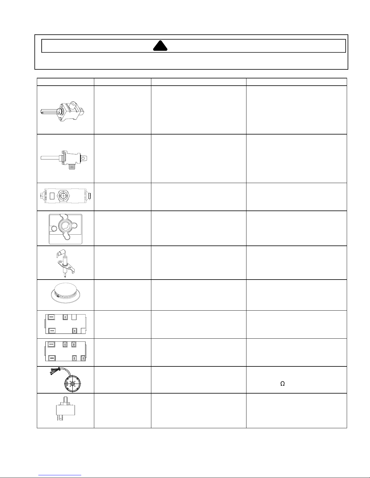
Illustration Component Test Procedure Results
Burner valve,
top, 360°
JGD8348CDP
Burner valve,
left and right, 360°
JGD8348CDP
Snap switch
JGD8348CDP
Dreefs spark
switch
JGD8348CDP
Burner ignition
electrode
JGD8348CDP
Verify gas is supplied.
Orifice adjusted for
Natural or LP.
Adjust set screw for simmer
control............................................
Verify gas is supplied.
Orifice adjusted for
Natural or LP.
Adjust set screw for simmer
control............................................
Test for voltage at terminals ..........
Disconnect wiring and check for
continuity in LITE position..............
Test for voltage at terminals ..........
Disconnect wiring and check for
continuity in LITE position..............
Test for resistance of spark lead ...
Test ignitor to chassis....................
To replace burner valve(s),
complete assembly must be
replaced (manifold and valves).
1650 BTU per hour minimum.
See conversion section.
To replace burner valve(s),
complete assembly must be
replaced (manifold and valves).
See conversion section.
120 VAC
Continuity in LITE position.
120 VAC
Continuity in LITE position.
Continuity
No continuity from ignitor to
chassis.
Sealed surface
burner
JGD8348CDP,
JGC8430BD*,
L
AB
JGC8645BDS
Spark module
2 + 0
B1N
A1
L
AB
JGD8348CDP
Spark module
4 + 0
B1N
A1
JGD8348CDP
Blower motor
assembly
JGD8348CDP
Rotary switch
JGD8348CDP
Verify gas is supplied..................... Check for obstructions in burner
ports.
Test for voltage at terminals
L and N ..........................................
Check polarity and ground.............
Test for voltage at terminals
L and N ..........................................
Check polarity and ground.............
Verify resistance between white
and black wires..............................
Test for voltage at terminals ..........
Disconnect wiring, reference
wiring diagram and check for
continuity in Lo and Hi positions ....
120 VAC
See wiring diagram
120 VAC
See wiring diagram
115 VAC, 60 Hz, 2.4 amps
1550 RPM, 1/10 HP, CWLE
Ω
Approx. 48
120 VAC
Continuity in Lo and Hi positions.
©2004 Maytag Services 16023565 13
 Loading...