

Page 1

PROPANE GAS AND HIGH ALTITUDE
IMPORTANT:
Installer:
Homeo
IMPOR
Installateur
Pr
.
CONVERSION INSTRUCTIONS
For JGC3530GS and JGC3536GS Model Series
INSTRUCTIONS DE CONVERSION—
GAZ PROPANE ET ALTITUDE ÉLEVÉE
Pour séries de modèles JGC3530GS et JGC3536GS
Table of Contents/Table des matières
COOKTOP SAFETY ........................................................................2
Tools and Parts .............................................................................3
Convert from Natural Gas to Propane Gas .................................3
Convert from Propane Gas to Natural Gas .................................6
Lighting the Electronic Igniters ....................................................8
Low Flame Height Adjustment .....................................................8
SÉCURITÉ DE LA TABLE DE CUISSON .....................................10
Outillage et pièces ......................................................................11
Conversion de gaz naturel à propane ........................................12
Conversion de propane à gaz naturel ........................................15
Allumeurs électroniques—allumage ..........................................17
Réglage pour le débit thermique minimum ...............................18
opriétaire : Conserver les instructions d'installation pour référence ultérieure
W11032278B
Leave installation instructions with the homeowner.
wner: Keep installation instructions for future reference.
TANT :
: Remettre les instructions d'installation au propriétaire.
Page 2
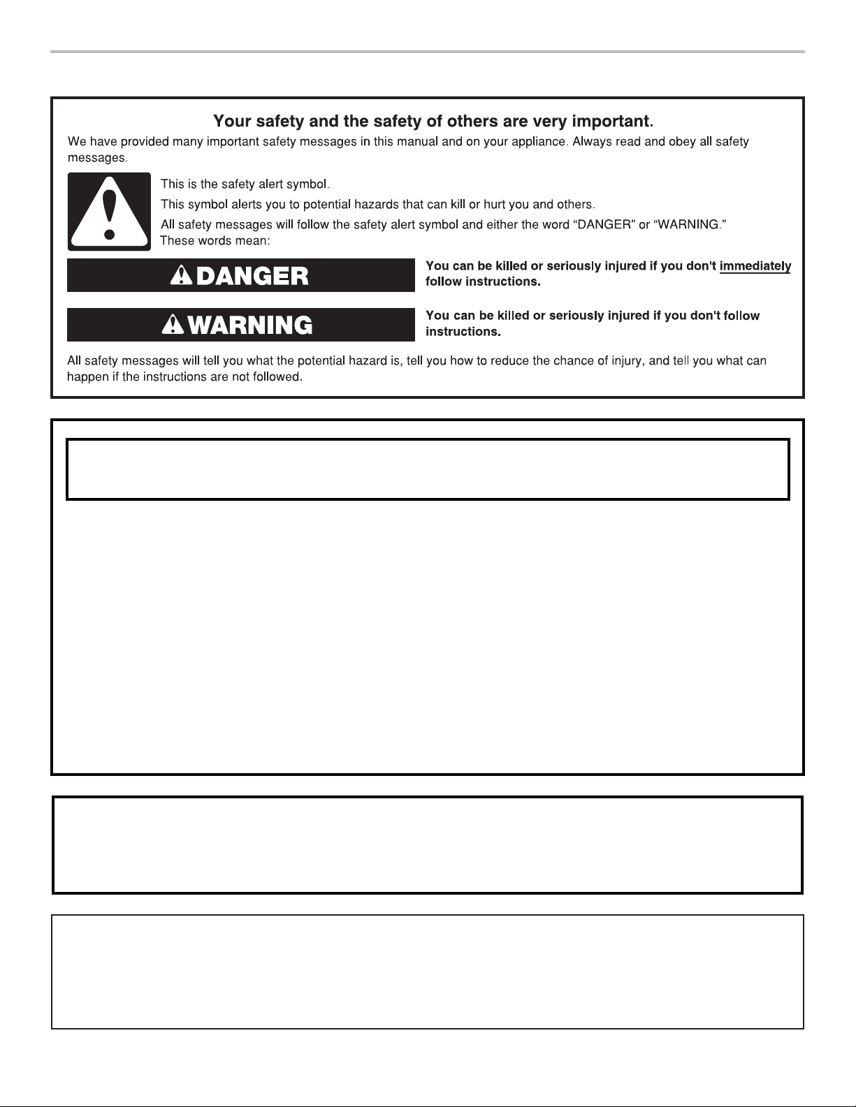
COOKTOP SAFETY
WARNING: If the information in these instructions is not followed exactly, a fire or
explosion may result causing property damage, personal injury or death.
– Do not store or use gasoline or other flammable vapors and liquids in the vicinity of this
or any other appliance.
– WHAT TO DO IF YOU SMELL GAS:
Do not try to light any appliance.
•
Do not touch any electrical switch.
•
Do not use any phone in your building.
•
Immediately call your gas supplier from a neighbor's phone. Follow the gas supplier's
•
instructions.
If you cannot reach your gas supplier, call the fire department.
•
Installation and service must be performed by a qualified installer, service agency or
–
the gas supplier.
WARNING: Gas leaks cannot always be detected by smell.
Gas suppliers recommend that you use a gas detector approved by UL or CSA.
For more information, contact your gas supplier.
If a gas leak is detected, follow the “What to do if you smell gas” instructions.
In the State of Massachusetts, the following installation instructions apply:
■ Installations and repairs must be performed by a qualified or licensed contractor, plumber, or gas fitter qualified or licensed by
the State of Massachusetts.
■ Acceptable Shut-off Devices: Gas Cocks and Ball Valves installed for use shall be listed.
■ A flexible gas connector, when used, must not exceed 4 feet (121.9 cm).
2
Page 3
Tools and Parts
Gather the required tools and parts necessary for correct
Propane gas conversion.
Tools needed
■ Flat-blade screwdriver
■ 3/32" (#0 [2.0 mm]) flat-blade screwdriver (screwdriver
shaft must be a minimum of 21/2" [6.4 cm] long)
■ Adjustable wrench
■ 7.0 mm nut driver
■ 7.0 mm wrench
Parts supplied
■ Propane orifice package (W10686634)
■ Conversion instructions (W10590570)
High Altitude Conversion
To convert the cooktop for elevations above 6,560 ft (1,999.5 m),
order a High Altitude Conversion Kit.
■ Part Number W10686630: Propane gas high altitude
■ Part Number W10686629: Natural gas high altitude
To order, see the “Assistance or Service” section of the Use and
Care Guide.
IMPORTANT: Gas conversions from Natural gas to Propane gas
must be done by a qualified installer. Before proceeding with
conversion, shut off the gas supply to the cooktop prior to
disconnecting the electrical power.
WARNING
This conversion kit shall be installed by a
qualified service agency in accordance
with the manufacturer's instructions and
all applicable codes and requirements of
the authority having jurisdiction. If the
information in these instructions is not
followed exactly, a fire, explosion or
production of carbon monoxide may
result causing property damage, personal
injury or loss of life. The qualified service
agency is responsible for the proper
installation of this kit. The installation is
not proper and complete until the
operation of the converted appliance is
checked as specified in the
manufacturer's instructions supplied with
this kit.
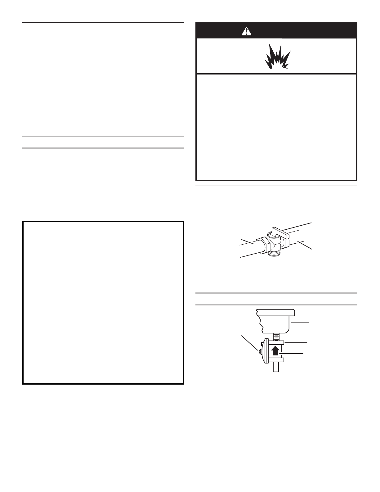
WARNING
Explosion Hazard
Use a new CSA International approved gas supply line.
Install a shut-off valve.
Securely tighten all gas connections.
If connected to propane, have a qualified person make
sure gas pressure does not exceed 14" (36 cm) water
column.
Examples of a qualified person include:
licensed heating personnel,
authorized gas company personnel, and
authorized service personnel.
Failure to do so can result in death, explosion, or fire.
Convert from Natural Gas
to Propane Gas
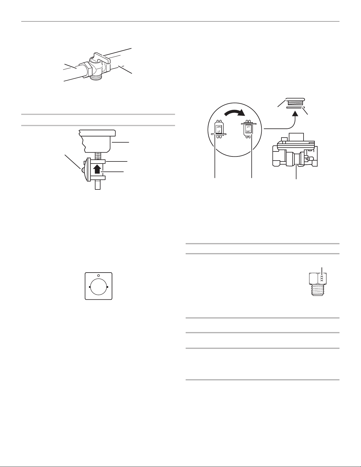
1. Turn manual shut-off valve to the closed position.
B
A
C
A. To cooktop
B. Shut-off valve (closed position)
C. Gas supply line
2. Unplug cooktop or disconnect power.
To Convert Gas Pressure Regulator
B
A
C
D
A. Access cap
B. Rear of cooktop
C. Gas pressure regulator
D. Gas flow
3. Determine the type of regulator you have:
Style 1: The cap has a slot and “NAT” printed on it.
Remove access cap by using a flat-blade screwdriver
or coin, turning the access cap counterclockwise.
3
Page 4
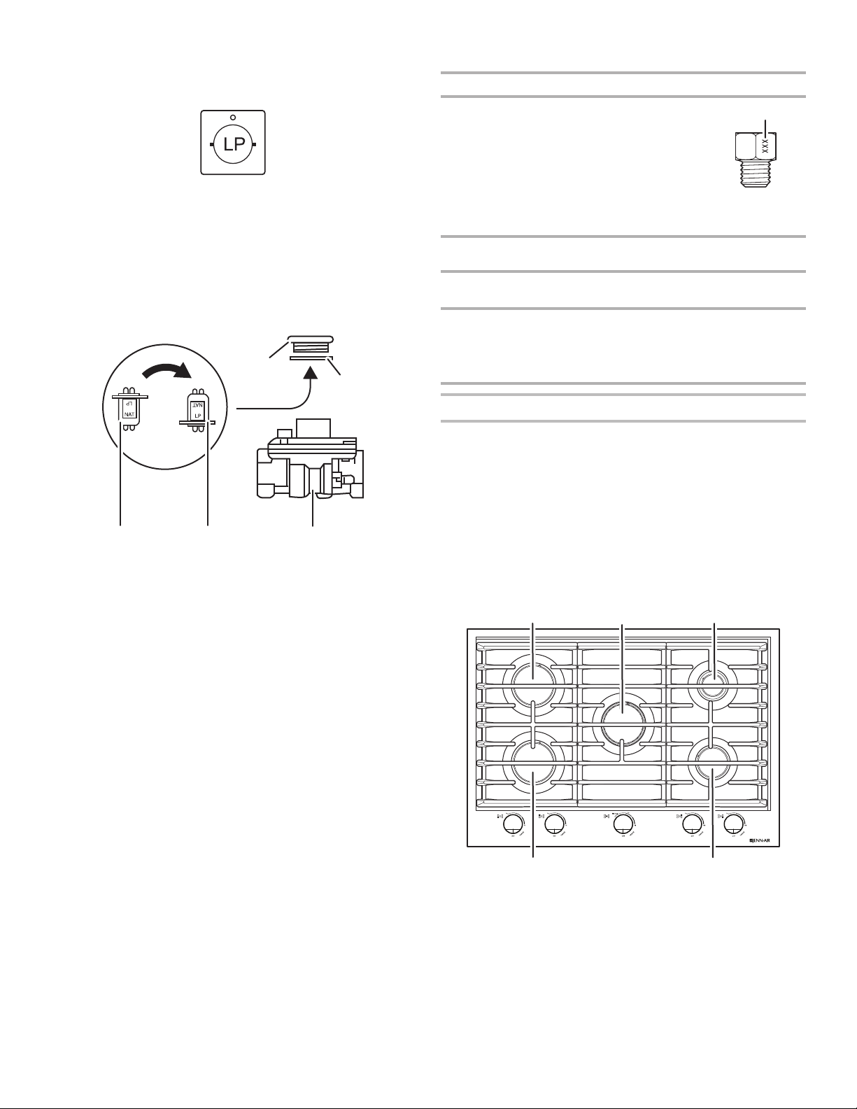
The gas pressure regulator has 2 settings that are stamped
on either side of the cap. Turn the cap and reinstall into
regulator with the stamp “LP” visible from the outside of
the regulator.
Style 2: The cap does not have a slot and requires a wrench
to be removed.
Remove the access cap by using a wrench, turning the
access cap counterclockwise.
Remove spring retainer from the cap by pushing against
the flat side of the spring retainer. Look at the spring retainer
to locate the “NAT” or “LP” position. Turn over the spring
retainer so the “LP” is showing on the bottom. Snap the
spring retainer back into the cap. Reinstall the cap onto
the regulator.
Propane Gas Orifice Spud Chart
Burner Rating Stamp (A) Size
1,500 BTU* 41 0.41 mm
5,000 BTU 66 0.66 mm
9,050 BTU 88 0.88 mm
12,000 BTU 102 1.02 mm
16,000 BTU 112 1.12 mm
* Simmer orifice for the dual stack (center) burner.
Burner Models
Model No.
JGC3530GS
Right
Front
9,000
BTU
Right
Rear
5,000
BTU
Center
16,000
BTU
A. Size stamp
Left
Front
12,000
BTU
12,000
BTU
A
Left
Rear
A
B
CDE
A. Access cap
B. Gasket
C. Gas pressure regulator
D. LP position
E. NAT position
4. Test the gas pressure regulator and gas supply line.
The regulator must be checked at a minimum 2.5 cm water
column above the set pressure. The inlet pressure to the
regulator should be as follows for operation and checking
the regulator setting:
Propane Gas:
Minimum pressure: 25.4 cm W.C.P.
Supply pressure: 35.5 cm W.C.P.
Gas Supply Pressure Testing
Line pressure testing above 1/2 psi (3.5 kPa) gauge
(35.5 cm WCP)
The cooktop and its individual shut-off valve must be
disconnected from the gas supply piping system during
any pressure testing of that system at test pressures in
excess of 1/2 psi (3.5 kPa).
Line pressure testing at 1/2 psi (3.5 kPa) gauge
(35.5 cm WCP) or lower
The cooktop must be isolated from the gas supply piping
system by closing its individual manual shut-off valve during
any pressure testing of the gas supply piping system at test
pressures equal to or less than 1/2 psi (3.5 kPa).
5. If the burner grates are installed, remove them.
Use the following charts to match the correct gas orifice
spud with the burner location and model being converted.
JGC3536GS
12,000
BTU
5,000
BTU
16,000
BTU
12,000
BTU
12,000
BTU
High Altitude Conversions
IMPORTANT: You must convert Propane gas with Propane
gas High Altitude Kit Part Number W10686630 or Natural gas
with Natural gas High Altitude Kit Part Number W10686629. If
you need to convert Propane gas to Natural gas high altitude
or Natural gas to Propane gas high altitude, you must convert
the pressure regulator. For this, follow steps 1 through 3 of the
necessary conversion.
Propane Gas Orifice Spud Chart for High Altitude Conversion
See chart in the “Propane Gas High Altitude Conversion Kit.”
Burner Locations
30" (76.2 cm) and 36" (91.4 cm) Models
A
A. Left rear burner
B. Center burner
C. Right rear burner
B
D. Right front burner
E. Left front burner
C
DE
4
Page 5
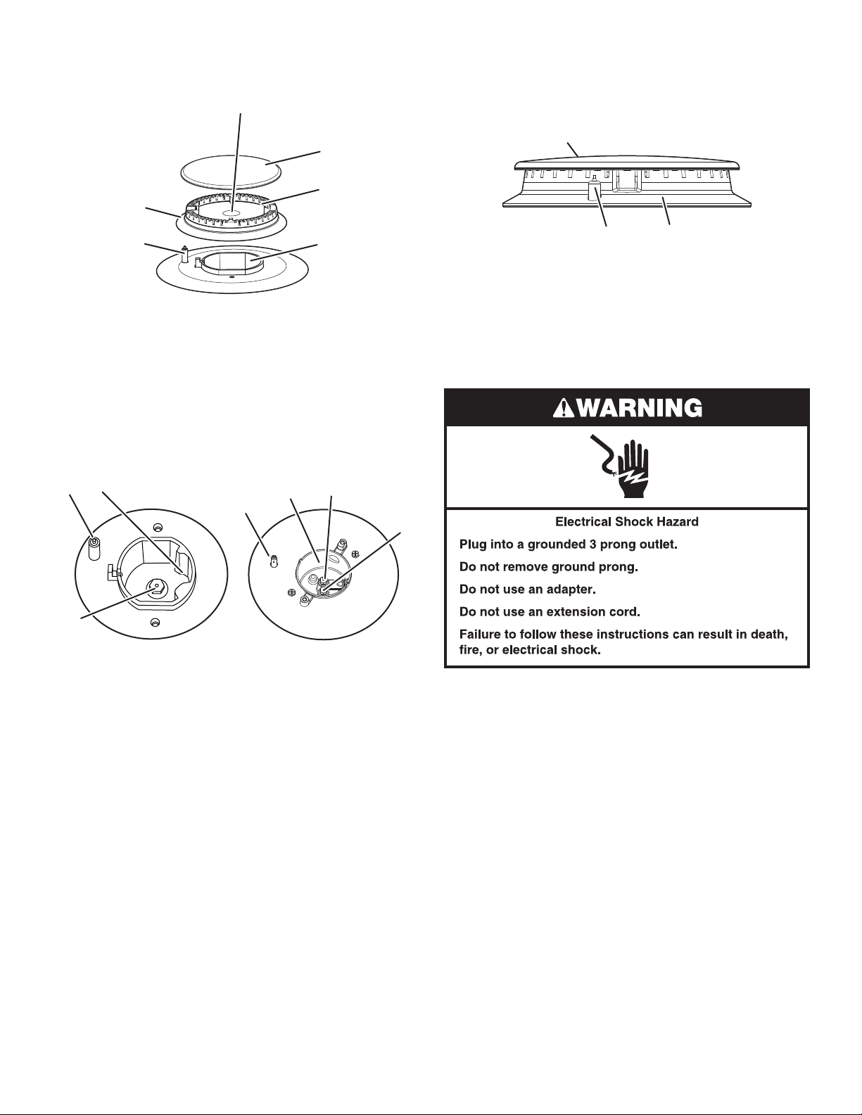
6. Remove all burner caps and burner bases. Be sure to keep
the cap and base for each burner together. This will assure
that the cap and base are reinstalled on the proper burner.
A
B
C
F
8. Replace burner bases and burner caps.
IMPORTANT: Be sure that the electrode aligns with the
notch or hole in the burner base. The igniter electrode is
ceramic and could break during installation of the burner
base.
A
DE
A. Gas tube opening
B. Burner cap
C. Burner base
D. Orifice holder
E. Igniter electrode
F. Burner base notch or hole
7. To convert burners:
■ Insert 7.0 mm nut driver down onto the gas orifice
spud (C) and remove by turning it counterclockwise
and lifting out.
■ Set gas orifice spud aside.
■ Replace with correct Propane gas orifice spud. See the
Propane Gas Orifice Spud Chart.
B
A
B
C
A
C
B
A. Burner cap
B. Electrode
C. Burner base
C
9. Open shut-off valve in the gas supply line. The valve is open
when the handle is parallel to the gas pipe.
10. Once you have completed converting all of the cooktop
burners, test the cooktop for leaks by brushing on an
approved noncorrosive leak-detection solution. If bubbles
appear, a leak is indicated. Correct any leaks found.
D
Standard and
simmer burners
A. Igniter electrode
B. Orifice holder
C. Orifice spud
Dual flame burner
A. Igniter electrode
B. Orifice holder
C. Orifice spud
D. Orifice simmer
IMPORTANT: Place Natural gas orifice spuds in plastic
parts bag for future use and keep with package containing
literature.
11. Plug in cooktop or reconnect power.
12. Adjust valve according to the “Low Flame Height
Adjustment” section.
5
Page 6
Convert from Propane Gas to Natural Gas
1. Turn manual shut-off valve to the closed position.
B
A
C
A. To cooktop
B. Shut-off valve (closed position)
C. Gas supply line
2. Unplug cooktop or disconnect power.
To Convert Gas Pressure Regulator
B
A
C
D
Style 2: The cap does not have a slot and requires a wrench
to be removed.
Remove the access cap by using a wrench, turning the
access cap counterclockwise.
Remove spring retainer from the cap by pushing against
the flat side of the spring retainer. Look at the spring retainer
to locate the “NAT” or “LP” position. Turn over the spring
retainer so the “NAT” is showing on the bottom. Snap the
spring retainer back into the cap. Reinstall the cap onto
the regulator.
A
B
A. Access cap
B. Rear of cooktop
C. Gas pressure regulator
D. Gas flow
3. Determine the type of regulator you have:
Style 1: The cap has a slot and “LP” printed on it.
Remove access cap by using a flat-blade screwdriver
or coin, turning the access cap counterclockwise.
The gas pressure regulator has 2 settings that are stamped
on either side of the cap. Turn the cap and reinstall into
regulator with the stamp “NAT” visible from the outside of
the regulator.
NAT
DE
A. Access cap
B. Gasket
C. Gas pressure regulator
D. NAT position
E. LP position
C
4. If the burner grates are installed, remove them.
Use the following charts to match the correct gas orifice
spud with the burner location and model being converted.
Natural Gas Orifice Spud Chart
Burner Rating Stamp (A) Size
1,300 BTU* 53 0.53 mm
6,000 BTU 110 1.10 mm
9,050 BTU 132 1.32 mm
12,000 BTU 155 1.55 mm
15,000 BTU 170 1.70 mm
20,000 BTU 195 1.95 mm
A. Size stamp
* Simmer orifice for the dual stack (center) burner.
Burner Models
Model No.
Right
Front
Right
Rear
Center
Left
Front
A
Left
Rear
JGC3530GS
JGC3536GS
9,000
BTU
12,000
BTU
6,000
BTU
6,000
BTU
20,000
BTU
20,000
BTU
12,000
BTU
12,000
BTU
12,000
BTU
15,000
BTU
6
Page 7

High Altitude Conversions
IMPORTANT: You must convert Propane gas with Propane
gas high altitude kit Part Number W10686630 or Natural gas
with Natural gas high altitude kit Part Number W10686629. If
you need to convert Propane gas to Natural gas high altitude
or Natural gas to Propane gas high altitude, you must convert
the pressure regulator. For this, follow steps 1 through 3 of the
necessary conversion.
Natural Gas Orifice Spud Chart for High Altitude Conversion
See chart in the “Natural Gas High Altitude Conversion Kit.”
B
A
B
C
A
D
C
Burner Locations
30" (76.2 cm) and 36" (91.4 cm) Models
A
A. Left rear burner
B. Center burner
C. Right rear burner
5. Remove all burner caps and burner bases. Be sure to keep
the cap and base for each burner together. This will assure
that the cap and base are reinstalled on the proper burner.
B
D. Right front burner
E. Left front burner
A
C
DE
B
Standard and
simmer burners
A. Igniter electrode
B. Orifice holder
C. Orifice spud
Dual flame burner
A. Igniter electrode
B. Orifice holder
C. Orifice spud
D. Orifice simmer
IMPORTANT: Place Propane gas orifice spuds in plastic
parts bag for future use and keep with package containing
literature.
7. Replace burner bases and burner caps.
IMPORTANT: Be sure that the electrode aligns with the
notch or hole in the burner base. The igniter electrode is
ceramic and could break during installation of the burner
base.
A
B
A. Burner cap
B. Electrode
C. Burner base
C
8. Open shut-off valve in the gas supply line. The valve is open
when the handle is parallel to the gas pipe.
9. Once you have completed converting all of the cooktop
burners, test the cooktop for leaks by brushing on an
approved noncorrosive leak-detection solution. If bubbles
appear, a leak is indicated. Correct any leaks found.
C
F
DE
A. Gas tube opening
B. Burner cap
C. Burner base
D. Orifice holder
E. Igniter electrode
F. Burner base notch or hole
6. To convert burners:
■ Insert 7.0 mm nut driver down onto the gas orifice
spud (C) and remove by turning it counterclockwise
and lifting out.
■ Set gas orifice spud aside.
■ Replace with correct Natural gas orifice spud. See the
Natural Gas Orifice Spud Chart.
10. Plug in cooktop or reconnect power.
11. Adjust valve according to the “Low Flame Height
Adjustment” section.
7
Page 8

Lighting the Electronic Igniters
The cooktop burners use electronic igniters in place of standing
pilots. When the cooktop control knob is pushed in and turned
to the IGNITE position, the system creates a spark to light the
burner. This sparking continues until a flame is present.
To Check Operation of the Cooktop Burners:
1. Push in and turn knobs to IGNITE. The cooktop burner
flame should light within 4 seconds. Turn the knobs to HI.
2. Turn the knobs to OFF.
3. Repeat steps 1 and 2 for the Lo and Simmer positions
4. If a burner does not light properly, turn the control knob to
OFF. Make sure the burner base and burner cap are in
their proper position.
Low Flame Height Adjustment
Each burner flame has been factory set to the lowest position
available to provide reliable and constant reignition of the burner.
However, each burner can be adjusted.
For Propane gas conversion:
Tighten (clockwise) screw “C” snugly to set the minimum flame
height. Do not adjust for a higher flame.
For Natural gas conversion:
Tighten (clockwise) screw “C” to reduce flame height. Loosen
(counterclockwise) screw to increase flame height.
To Adjust:
The flame can be adjusted using the adjustment screws
underneath the control knob.
1. Set the burner flame to LO.
2. Remove the control knob.
3. For single valves, hold the knob stem with a pair of pliers.
Use a 3/32" (#0 [2.0 mm]) flat-blade screwdriver to turn the
screw located within the shaft of the control knob stem until
the flame is the proper size.
A
B
A. Correct
B. Incorrect
5. Check that the power supply cord is plugged in and circuit
breaker has been tripped or household fuse has not blown.
6. Check that the shut-off valve is in the open position.
7. Check burner operation again.
If one or all of the burners do not light at this point, see the
“Warranty” section in the Use and Care Guide.
C
A. 3/32" (2.0 mm)—#0 flat-blade
screwdriver (shaft must be a
minimum of 21/2" [6.4 cm] long)
B. Control knob stem opening
C. Adjustment screw location
4. For the center burner dual valve, use a 3/32" (#0 [2.0 mm])
flat-blade screwdriver to turn the screw located on the
bottom, upper surface of the valve until the flame is the
proper size.
B
A
A. Adjustment screw location
B. 3/32" (2.0 mm)—#0 flat-blade
screwdriver (shaft must be a
minimum of 2
1
/2" [6.4 cm] long)
8
Page 9

5. Replace the control knob.
6. Repeat steps 1 through 5 for each burner.
7. Check burner flame(s) for proper size and shape. The
cooktop “low” burner flame should be a steady blue
flame approximately 1/4" (6.4 mm) high.
A
B
Standard burner
A. Low flame
B. High flame
A
B
Dual flame burner
A. Simmer flame
B. High flame
8. Completely fill out the conversion label and attach label to
bottom of the cooktop next to the rating tag. Do not cover
the rating tag with the conversion label.
9. Save the orifices removed from the cooktop along with these
instructions for future reference.
Read the “Sealed Surface Burners” section in the Use and Care
Guide supplied with your cooktop.
9
Page 10

SÉCURITÉ DE LA TABLE DE CUISSON
AVERTISSEMENT : Si les renseignements dans ces instructions ne sont pas
exactement observés, un incendie ou une explosion peut survenir, causant des
dommages au produit, des blessures ou un décès.
– Ne pas entreposer ni utiliser de l’essence ou d’autres vapeurs ou liquides inflammables
à proximité de cet appareil ou de tout autre appareil électroménager.
– QUE FAIRE DANS LE CAS D’UNE ODEUR DE GAZ :
Ne pas tenter d’allumer un appareil.
•
Ne pas toucher à un commutateur électrique.
•
Ne pas utiliser le téléphone se trouvant sur les lieux.
•
Appeler immédiatement le fournisseur de gaz à partir du téléphone d'un voisin. Suivre
•
ses instructions.
À défaut de joindre votre fournisseur de gaz, appeler les pompiers.
•
– L’installation et l’entretien doivent être effectués par un installateur qualifié, une agence
de service ou le fournisseur de gaz.
AVERTISSEMENT : L’odorat ne permet pas toujours la détection d’une fuite de gaz.
Les distributeurs de gaz recommandent l’emploi d’un détecteur de gaz (homologation UL ou CSA).
Pour d’autre information, contacter le fournisseur de gaz local.
En cas de détection d’une fuite de gaz, exécuter les instructions “Que faire dans le cas d’une odeur de gaz”.
Dans l’État du Massachusetts, les instructions d’installation suivantes sont applicables :
■ Les travaux d’installation et réparation doivent être exécutés par un plombier ou tuyauteur qualifié ou licencié, ou par le
personnel qualifié d’une entreprise licenciée par l’État du Massachusetts.
■ Remplacer par des dispositifs de fermeture acceptables : Les robinets de gaz et robinets à bille installés pour l'utilisation
devraient être indiqués.
■ Si un conduit de raccordement flexible est utilisé, sa longueur ne doit pas dépasser 4 pi (121,9 cm).
10
Page 11

Outillage et pièces
Rassembler les outils et composants nécessaires pour
l’exécution correcte de la conversion pour l’alimentation
au gaz propane.
Outillage nécessaire
■ Tournevis à lame plate
■ Tournevis à lame plate de 3/32" (#0 [2,0 mm]) (la longueur
de la tige du tournevis doit être d’au moins 21/2" [6,4 cm])
■ Clé à molette
■ Tourne-écrou de 7 mm
■ Clé de 7 mm
Pièces fournies
■ Ensemble de gicleurs pour gaz propane (W10686634)
■ Instructions pour la conversion (W10590570)
Conversion pour altitude élevée
Pour convertir la table de cuisson pour l’utilisation à une altitude
supérieure à 6 560 pi (1 999,5 m), commander un ensemble de
conversion pour altitude élevée.
■ Produit numéro W10686630—altitude élevée—propane
■ Produit numéro W10686629—altitude élevée—gaz naturel
Pour la commande, voir la section “Assistance ou service” dans
le Guide d’utilisation et d’entretien.
IMPORTANT : L’opération de conversion de l’appareil pour
l’alimentation au gaz propane au lieu de gaz naturel doit être
exécutée par un installateur qualifié. Avant d’entreprendre
la conversion, fermer l’arrivée de gaz avant d’interrompre
l’alimentation électrique de l’appareil.
AVERTISSEMENT
Cet ensemble de conversion doit être
installé par le personnel qualifié d'une
agence de service en conformité avec les
instructions du fabricant et les
prescriptions de tous les codes en vigueur
et des autorités juridictionnelles. Si les
présentes instructions ne sont pas
rigoureusement respectées, ceci peut
provoquer un incendie, une explosion ou
la génération de monoxyde de carbone
provoquant des dommages corporels ou
matériels, ou même la mort. La
responsabilité de l'installation correcte de
cet ensemble de conversion incombe au
personnel qualifié d'une agence de
service. L'installation n'est pas correcte et
complète avant que le bon fonctionnement
de l'appareil converti ait été vérifié sur la
base des spécifications présentées dans
les instructions du fabricant fournies avec
cet ensemble de pièces.
AVERTISSEMENT
Risque d'explosion
Utiliser une canalisation neuve d'arrivée de gaz
approuvée par la CSA International.
Installer un robinet d'arrêt.
Bien serrer chaque organe de connexion de la
canalisation de gaz.
En cas de connexion au gaz propane, demander à une
personne qualifiée de s'assurer que la pression de gaz
ne dépasse pas 36 cm (14 po) de la colonne d'eau.
Par personne qualifiée, on comprend :
le personnel autorisé de chauffage,
le personnel autorisé d'une compagnie de gaz, et
le personnel d'entretien autorisé.
Le non-respect de ces instructions peut causer
un décès, une explosion ou un incendie.
11
Page 12

Conversion de gaz naturel à propane
1. Fermer le robinet d’arrêt manuel.
B
A
C
A. Vers table de cuisson
B. Robinet d’arrêt (position de fermeture)
C. Canalisation de gaz
2. Débrancher la table de cuisson ou déconnecter la source
de courant électrique.
Conversion du détendeur
B
A
C
Style 2 : Le chapeau ne comporte pas de rainure; on doit
utiliser une clé pour la dépose.
Utiliser une clé pour enlever le chapeau de l’ouverture
d’accès; faire tourner le chapeau dans le sens antihoraire.
Ôter le ressort de retenue qui se trouve sous le chapeau—
pousser contre le côté plat du ressort de retenue. Examiner
le ressort de retenue pour identifier la position “NAT” ou
“LP”. Orienter correctement le ressort de retenue pour que
la mention “LP” soit au fond. Réinstaller le ressort de retenue
dans le chapeau. Réinstaller le chapeau sur le détendeur.
A
B
D
A. Chapeau de l’ouverture d’accès
B. Arrière de la table de cuisson
C. Détendeur
D. Sens de circulation du gaz
3. Déterminer le type du détendeur :
Style 1 : Le chapeau comporte une rainure et la
mention “NAT”.
Utiliser un tournevis à lame plate ou une pièce de monnaie
pour dévisser le chapeau de l’ouverture d’accès; faire
tourner le chapeau dans le sens antihoraire.
Deux positions sont possibles pour le détendeur;
l’information correspondante est gravée de chaque côté du
chapeau. Orienter le chapeau correctement, et réinstaller le
chapeau sur le détendeur; la mention “LP” doit être visible
depuis l’extérieur du détendeur.
CDE
A. Chapeau de
l’ouverture d’accès
B. Joint d’étanchéité
C. Détendeur
D. Position LP
E. Position NAT
4. Tester le détendeur et la canalisation de gaz.
On doit tester le détendeur sous une pression supérieure
d’au moins 2,5 cm (colonne d’eau) à la pression de réglage.
Pour le fonctionnement et le contrôle du réglage du
détendeur, il faut que la pression d’admission au détendeur
corresponde aux indications ci-dessous :
Gaz propane :
Pression minimum : 25,4 cm (colonne d’eau)
Pression de service : 35,5 cm (colonne d’eau)
Test de pressurisation de la canalisation de gaz
Pressurisation à une pression supérieure à 1/2 lb/po²
(3,5 kPa) (35,5 cm - colonne d’eau)
Lors de tout test de pressurisation de ce système à
une pression supérieure à 1/2 lb/po² (3,5 kPa), on doit
déconnecter l’appareil et son robinet d’arrêt individuel
de la canalisation de gaz.
Pressurisation à une pression relative de 1/2 lb/po²
(3,5 kPa) (35,5 cm - colonne d’eau) ou moins
Lors de tout test de pressurisation de la canalisation de gaz
à une pression égale ou inférieure à 1/2 lb/po² (3,5 kPa), on
doit isoler l’appareil de la canalisation de gaz en fermant son
robinet d’arrêt manuel individuel.
12
Page 13

5. Enlever les grilles de brûleur si elles sont installées.
Dans les tableaux qui suivent, choisir le gicleur approprié
selon le modèle de l’appareil et l’emplacement du brûleur
à convertir.
Tableau des gicleurs pour propane
Positions des brûleurs
Modèles de 30" (76,2 cm) et 36" (91,4 cm)
A
B
C
Puissance
thermique
1 500 BTU* 41 0,41 mm
Empreinte (A) Taille
A
5 000 BTU 66 0,66 mm
9 050 BTU 88 0,88 mm
12 000 BTU 102 1,02 mm
16 000 BTU 112 1,12 mm
A. Empreinte
de la taille
* Gicleur de mijotage du brûleur double (central).
Modèle de brûleur
Modèle n°
JGC3530GS
JGC3536GS
Avant
droit
9 000
BTU
12 000
BTU
Arrière
droit
5 000
BTU
5 000
BTU
Central
16 000
BTU
16 000
BTU
Avant
gauche
12 000
BTU
12 000
BTU
Arrière
gauche
12 000
BTU
12 000
BTU
Conversions pour utilisation en haute altitude
IMPORTANT : Convertir le modèle au gaz propane avec
l’ensemble pour gaz propane en haute altitude référence
W10686630. Pour le modèle au gaz naturel, utiliser l’ensemble
pour gaz naturel en haute altitude référence W10686629. Pour
convertir un modèle au gaz propane en modèle au gaz naturel en
haute altitude, ou un modèle au gaz naturel en un modèle au gaz
propane en haute altitude, le détenteur doit être converti. Pour
réaliser la conversion, suivre les étapes 1 à 3.
Tableau des gicleurs à gaz propane pour la conversion en
haute altitude
Voir le tableau de la section “Ensemble pour conversion pour
alimentation au propane/altitude élevée”.
DE
A. Brûleur arrière gauche
B. Brûleur central
C. Brûleur arrière droit
D. Brûleur avant droit
E. Brûleur avant gauche
6. Retirer les chapeaux et bases de tous les brûleurs. Veiller à
conserver ensemble le chapeau et la base de chaque brûleur
afin de s’assurer que le chapeau et la base seront bien
installés sur le brûleur correct.
A
B
C
F
DE
A. Ouverture du tube
d’arrivée de gaz
B. Chapeau du brûleur
C. Base du brûleur
D. Porte-gicleur
E. Électrode d’allumage
F. Encoche ou trou à la base
du brûleur
13
Page 14

7. Pour convertir les brûleurs :
■ Placer le tourne-écrou de 7,0 mm sur le gicleur (C); faire
tourner dans le sens antihoraire et soulever pour enlever
le gicleur.
■ Conserver à part le gicleur du brûleur.
■ Remplacer le gicleur par un gicleur pour gaz propane de
taille correcte. Voir le Tableau de sélection des gicleurs
pour gaz propane.
9. Ouvrir le robinet d’arrêt de la canalisation de gaz. Le robinet
est ouvert lorsque la poignée est parallèle au conduit
d’alimentation en gaz.
10. Après avoir exécuté la conversion de chaque brûleur de la
table de cuisson, effectuer un test de recherche des fuites
en appliquant une solution homologuée (non corrosive) pour
détection des fuites sur les connexions du circuit de gaz.
L’apparition de bulles indique une fuite. Éliminer toute
fuite détectée.
B
A
B
C
A
C
Brûleurs standard
et pour mijotage
A. Électrode d’allumage
B. Porte-gicleur
C. Gicleur
Brûleur à double flamme
A. Électrode d’allumage
B. Porte-gicleur
C. Gicleur
D. Orifice pour mijotage
IMPORTANT : Placer les gicleurs pour gaz naturel dans le
sachet de pièces en plastique et les conserver avec le sachet
de documentation, pour pouvoir les réutiliser ultérieurement.
8. Replacer les bases et chapeaux de brûleur.
IMPORTANT : Veiller à aligner l’électrode avec l’encoche
ou le trou à la base du brûleur. L’électrode d’allumage est
en céramique et peut se briser durant l’installation de la
base du brûleur.
A
D
11. Brancher la table de cuisson ou reconnecter la source de
courant électrique.
12. Régler le robinet en suivant la section “Réglage pour le débit
thermique minimum”.
B
A. Chapeau du brûleur
B. Électrode
C. Base du brûleur
C
14
Page 15

Conversion de propane à gaz naturel
1. Fermer le robinet d’arrêt manuel.
B
A
C
A. Vers table de cuisson
B. Robinet d’arrêt (position de fermeture)
C. Canalisation de gaz
2. Débrancher la table de cuisson ou déconnecter la source
de courant électrique.
Conversion du détendeur
B
A
C
Style 2 : Le chapeau ne comporte pas de rainure; on doit
utiliser une clé pour la dépose.
Utiliser une clé pour enlever le chapeau de l’ouverture
d’accès; faire tourner le chapeau dans le sens antihoraire.
Ôter le ressort de retenue qui se trouve sous le chapeau en
poussant contre le côté plat du ressort de retenue. Examiner
le ressort de retenue pour identifier la position “NAT” ou
“LP”. Orienter correctement le ressort de retenue pour que la
mention “NAT” soit au fond. Réinstaller le ressort de retenue
dans le chapeau. Réinstaller le chapeau sur le détendeur.
A
B
D
A. Chapeau de l’ouverture d’accès
B. Arrière de la table de cuisson
C. Détendeur
D. Sens de circulation du gaz
3. Déterminer le type du détendeur :
Style 1 : Le chapeau comporte une rainure et la
mention “LP”.
Utiliser un tournevis à lame plate ou une pièce de monnaie
pour dévisser le chapeau de l’ouverture d’accès; faire
tourner le chapeau dans le sens antihoraire.
Deux positions sont possibles pour le détendeur;
l’information correspondante est gravée de chaque côté du
chapeau. Orienter le chapeau correctement, et réinstaller le
chapeau sur le détendeur; la mention “NAT” doit être visible
depuis l’extérieur du détendeur.
NAT
DE
A. Chapeau de
l’ouverture d’accès
B. Joint d’étanchéité
C. Détendeur
D. Position NAT
E. Position LP
C
4. Enlever les grilles de brûleur si elles sont installées.
Dans les tableaux qui suivent, choisir le gicleur approprié
selon le modèle de l’appareil et l’emplacement du brûleur
à convertir.
Tableau des gicleurs pour gaz naturel
Puissance
thermique
1 300 BTU* 53 0,53 mm
6 000 BTU 110 1,10 mm
9 050 BTU 132 1,32 mm
12 000 BTU 155 1,55 mm
15 000 BTU 170 1,70 mm
20 000 BTU 195 1,95 mm
* Gicleur de mijotage du brûleur double (central).
Empreinte
(A)
Taille
A. Empreinte
de la taille
Modèles de brûleur
A
Modèle n°
JGC3530GS
JGC3536GS
Avant
droit
9 000
BTU
12 000
BTU
Arrière
droit
6 000
BTU
6 000
BTU
Central
20 000
BTU
20 000
BTU
Avant
gauche
12 000
BTU
12 000
BTU
Arrière
gauche
12 000
BTU
15 000
BTU
15
Page 16

Conversions pour utilisation en haute altitude
IMPORTANT : Convertir le modèle au gaz propane avec
l’ensemble pour gaz propane en haute altitude référence
W10686630. Pour le modèle au gaz naturel, utiliser l’ensemble
pour gaz naturel en haute altitude référence W10686629. Pour
convertir un modèle au gaz propane en modèle au gaz naturel en
haute altitude, ou un modèle au gaz naturel en un modèle au gaz
propane en haute altitude, le détenteur doit être converti. Pour
réaliser la conversion, suivre les étapes 1 à 3.
Tableau des gicleurs à gaz naturel pour la conversion en
haute altitude
Voir le tableau de la section “Ensemble pour conversion au gaz
naturel/altitude élevée”.
Positions des brûleurs
Modèles de 30" (76,2 cm) et 36" (91,4 cm)
A
B
C
6. Pour convertir les brûleurs :
■ Placer le tourne-écrou de 7,0 mm sur le gicleur (C); faire
tourner dans le sens antihoraire et soulever pour enlever
le gicleur.
■ Conserver à part le gicleur du brûleur.
■ Remplacer le gicleur par un gicleur pour gaz naturel de
taille correcte. Voir le Tableau de sélection des gicleurs
pour gaz naturel.
B
A
B
C
A
C
D
DE
A. Brûleur arrière gauche
B. Brûleur central
C. Brûleur arrière droit
D. Brûleur avant droit
E. Brûleur avant gauche
5. Retirer les chapeaux et bases de tous les brûleurs. Veiller à
conserver ensemble le chapeau et la base de chaque brûleur
afin de s’assurer que le chapeau et la base seront bien
installés sur le brûleur correct.
A
B
C
F
Brûleurs standard
et pour mijotage
A. Électrode d’allumage
B. Porte-gicleur
C. Gicleur
Brûleur à double flamme
A. Électrode d’allumage
B. Porte-gicleur
C. Gicleur
D. Orifice pour mijotage
IMPORTANT : Placer les gicleurs pour propane dans le
sachet en plastique contenant les pièces et conserver
le tout avec le sachet de documentation pour pouvoir le
réutiliser ultérieurement.
7. Replacer les bases et chapeaux de brûleur.
IMPORTANT : Veiller à aligner l’électrode avec l’encoche
ou le trou à la base du brûleur. L’électrode d’allumage est
en céramique et peut se briser durant l’installation de la
base du brûleur.
A
B
A. Chapeau du brûleur
B. Électrode
C. Base du brûleur
C
16
A. Ouverture du tube
d’arrivée de gaz
B. Chapeau du brûleur
C. Base du brûleur
DE
D. Porte-gicleur
E. Électrode d’allumage
F. Encoche ou trou à la
base du brûleur
Page 17

8. Ouvrir le robinet d’arrêt de la canalisation de gaz. Le robinet
est ouvert lorsque la poignée est parallèle au conduit
d’alimentation en gaz.
9. Après avoir exécuté la conversion de chaque brûleur de la
table de cuisson, effectuer un test de recherche des fuites
en appliquant une solution homologuée (non corrosive) pour
détection des fuites sur les connexions du circuit de gaz.
L’apparition de bulles indique une fuite. Éliminer toute
fuite détectée.
10. Brancher la table de cuisson ou reconnecter la source de
courant électrique.
11. Régler le robinet en suivant la section “Réglage pour le débit
thermique minimum”.
Allumeurs électroniques—
allumage
À la place de flammes de veille, les brûleurs de la table
de cuisson sont dotés d’allumeurs électroniques. Lorsque
l’utilisateur appuie sur le bouton de commande et le fait tourner
jusqu’à IGNITE (allumage), le système génère des étincelles pour
l’inflammation du gaz sur le brûleur. Ces étincelles se produisent
jusqu’à l’apparition d’une flamme.
Contrôle du fonctionnement des brûleurs de la table
de cuisson :
1. Appuyer sur le bouton de commande et le tourner à IGNITE
(allumage). La flamme doit apparaître sur le brûleur en
moins de 4 secondes. Tourner le bouton de commande
à la position HI (élevée).
2. Tourner le bouton de commande à OFF (arrêt).
3. Répéter les étapes 1 et 2 pour les positions Lo (réglage bas)
et Simmer (mijotage).
4. Si le brûleur ne s’allume pas correctement, tourner le bouton
de commande à OFF (arrêt). Vérifier que le chapeau de
brûleur et la base de brûleur sont en position correcte.
A. Correct
B. Incorrect
5. Vérifier que le cordon d’alimentation électrique est branché,
que le tableau de disjoncteurs ne s’est pas déclenché et
qu’aucun fusible n’est grillé.
6. Vérifier que le robinet d’arrêt de la canalisation de gaz
est ouvert.
7. Contrôler de nouveau le fonctionnement du brûleur.
Si l’un des brûleurs ne peut toujours pas s’allumer, voir la section
“Garantie” dans le Guide d’utilisation et d’entretien.
17
Page 18

Réglage pour le débit thermique minimum
La flamme de chaque brûleur a été réglée en usine à la position
la plus basse pour que le dispositif de réallumage du brûleur
fonctionne constamment d’une manière fiable. Cependant, il est
possible de régler chaque brûleur.
Conversion au gaz propane :
Serrer solidement la vis “C” dans le sens horaire pour régler
la hauteur de flamme minimale. Ne pas régler sur une flamme
plus haute.
Conversion au gaz naturel :
Serrer la vis “C” dans le sens horaire pour réduire la hauteur
de la flamme. Desserrer la vis dans le sens antihoraire pour
augmenter la hauteur de flamme.
Réglage :
La taille des flammes peut être réglée à l’aide des vis de réglage
situées sous le bouton de commande.
1. Régler la flamme du brûleur sur LO (réglage bas).
2. Ôter le bouton de commande.
3. Pour les robinets uniques, immobiliser la tige de commande
avec une pince. Utiliser un tournevis à lame plate de 3/32"
(#0 [2,0 mm]) pour faire tourner la vis située dans la tige du
bouton de commande jusqu’à ce que la flamme atteigne la
taille adéquate.
4. Pour le robinet double du brûleur central, tourner la vis située
sur la face supérieure du fond du robinet au moyen d’un
tournevis à lame plate de 3/32" (n° 0 [2,0 mm]) jusqu’à ce
que la flamme atteigne la taille adéquate.
B
A
A. Emplacement de la vis de réglage
B. Tournevis à lame plate de 3/32"
(2,0 mm) n° 0 (la tige doit mesurer
au moins 2
1
/2" [6,4 cm] de long)
5. Réinstaller le bouton de commande.
6. Répéter les étapes 1 à 5 pour chaque brûleur.
7. Contrôler la taille et la forme des flammes sur chaque
brûleur. Pour le réglage au débit thermique minimum, on doit
observer des flammes stables bleues de 1/4" (6,4 mm).
A
B
C
A. Tournevis à lame plate de 3/32" (2,0 mm)
n° 0 (la tige doit mesurer au moins 21/2"
[6,4 cm] de long)
B. Orifice de la tige du bouton de commande
C. Emplacement de la vis de réglage
A
B
Brûleur standard
A. Débit thermique minimum
B. Débit thermique maximum
A
B
Brûleur à double flamme
A. Flamme de mijotage
B. Débit thermique maximum
8. Compléter l’étiquette de conversion; fixer l’étiquette sur le
fond de la table de cuisson, à côté de la plaque signalétique.
Ne pas recouvrir la plaque signalétique avec l’étiquette.
9. Conserver les gicleurs qui ont été retirés de la table de
cuisson avec les présentes instructions, pour utilisation
ultérieure.
Lire la section “Brûleurs de surface scellés” dans le Guide
d’utilisation et d’entretien fourni avec la table de cuisson.
18
Page 19

Notes
19
Page 20

W11032278B
®
/™ ©2017 Used under license in Canada. All rights reserved.
Utilisé sous licence au Canada. Tous droits réservés.
02/17
 Loading...