

Jenn-Air JED8130ADB15, JED8130ADW15 Installation Guide
READ "SAFETY INSTRUCTIONS" IN USE & CARE BOOK BEFORE USING UNIT
In order to assure the best results in service, proper operation and maximum efficiency, the original installation and adjustment
should be made by your dealer, his authorized agent, or by your local utility company before you attempt to operate the surface
unit.
LOCATION
Place unit where itwill be well lighted. For proper cooking results, it must be level. THESE ELECTRIC COUNTER MOUNTED
SURFACE UNITS ARE APPROVED FOR INSTALLATION IN COMBUSTIBLE CABINETRY. SEE INSTALLATION
DIAGRAM FOR THE APPROPRIATE UNIT ON THE FOLLOWING PAGES OF THIS INSTRUCTION SHEET.
OUTSIDE WIRING
Your local utility company will tell you whether the present
electric service to your home is adequate. It may be
necessary to increase the size of the wiring to the house and
service switch to take care of the electrical load demanded
by the surface unit and/or oven. The wattage (K.W. rating)
load for the range is specified on the name plate on the unit.
HOUSE WIRING
Most local building regulations and codes require that all
electrical wiring be done by licensed electricians. All wiring
should conform to Local and National Electrical Codes. This
unit requires a single phase three wire 120/240 or a 120/208
volt, 60 Hz, AC circuit. Wiring codes require that a separate
circuit be run from the main entrance panel to the unit and
that it be equipped with separate disconnect switch and
fuses, either in the main entrance panel or in a separate
switch and fuse box.
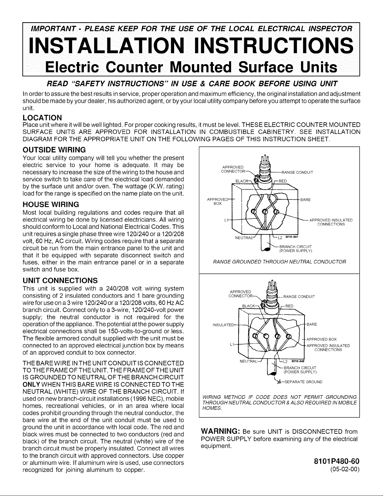
APPROVED
CONNECTOR_
APPRoOxVE_
NEUTRAL'-'
RANGE GROUNDED THROUGH NEUTRAL CONDUCTOR
_RANGE CONDUIT
_ APPROVED INSULATED
L2 9219-947
BRANCH CIRCUIT
(POWER SUPPLY)
CONNECTIONS
UNIT CONNECTIONS
This unit is supplied with a 240/208 volt wiring system
consisting of 2 insulated conductors and 1 bare grounding
wire for use on a3 wire 120/240 or a 120/208 volts, 60 Hz AC
branch circuit. Connect only to a 3-wire, 120/240-volt power
supply; the neutral conductor is not required for the
operation of the appliance. The potential at the power supply
electrical connections shall be 150-volts-to-ground or less.
The flexible armored conduit supplied with the unit must be
connected to an approved electrical junction box by means
of an approved conduit to box connector.
THE BARE WIRE IN THE UNIT CONDUIT IS CONNECTED
TO THE FRAME OF THE UNIT. THE FRAME OF THE UNIT
IS GROUNDED TO NEUTRAL OF THE BRANCH CIRCUIT
ONLY WHEN THIS BARE WIRE IS CONNECTED TO THE
NEUTRAL (WHITE) WIRE OF THE BRANCH CIRCUIT. If
used on new branch-circuit installations (1996 NEC), mobile
homes, recreational vehicles, or in an area where local
codes prohibit grounding through the neutral conductor, the
bare wire at the end of the unit conduit must be used to
ground the unit in accordance with local code. The red and
black wires must be connected to two conductors (red and
black) of the branch circuit. The neutral (white) wire of the
branch circuit must be properly insulated. Connect all wires
to the branch circuit with approved connectors. Use copper
or aluminum wire. If aluminum wire is used, use connectors
recognized for joining aluminum to copper.
APPROVED
CONNECTOR-_
INSULATED-- B_
L1--
NEUTRAL --/
WIRING METHOD IF CODE DOES NOT PERMIT GROUNDING
THROUGH NEUTRAL CONDUCTOR & ALSO REQUIRED IN MOBILE
HOMES.
-- RANGE CONDUIT
)_ -BARE
(
i
I._L2 9219-948
BRANCH CIRCUIT
L_ POWER SUPPLY
I"_,--S EPARATE GROUND
-APPROVED B©X
"APPRQVEDtNSULATED
CONNECTIONS
WARNING: Be sure UNIT is DISCONNECTED from
POWER SUPPLY before examining any of the electrical
equipment.
8101 P480-60
(05-02-00)
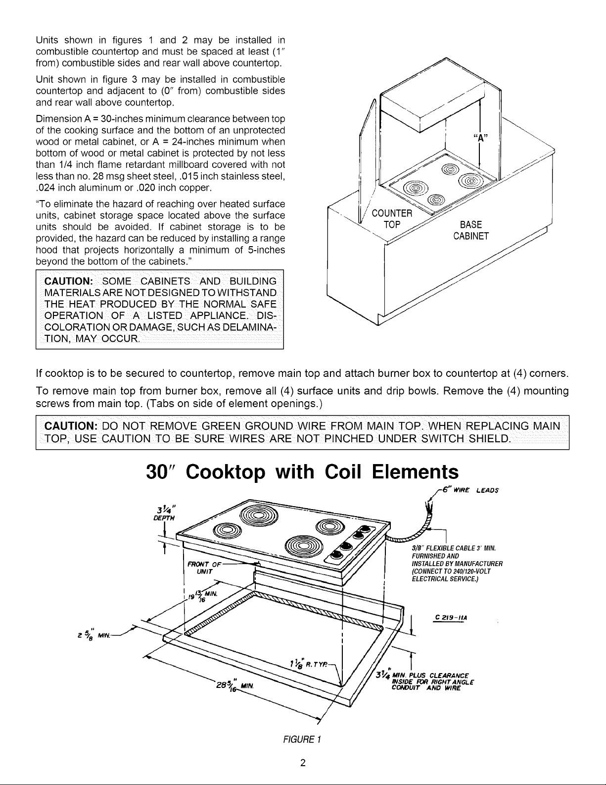
Unitsshownin figures1 and 2 maybe installedin
combustiblecountertopandmustbespacedatleast(1"
from)combustiblesidesandrearwallabovecountertop.
Unitshowninfigure3 maybeinstalledin combustible
countertopandadjacentto (0"from)combustiblesides
andrearwallabovecountertop.
DimensionA=30-inchesminimumclearancebetweentop
ofthecookingsurfaceandthebottomofanunprotected
woodor metalcabinet,orA =24-inchesminimumwhen
bottomofwoodor metalcabinetisprotectedbynotless
than1/4inchflameretardantmillboardcoveredwithnot
lessthanno.28msgsheetsteel,.015inchstainlesssteel,
.024inchaluminumor .020inchcopper.
"Toeliminatethehazardofreachingoverheatedsurface
units,cabinetstoragespacelocatedabovethesurface
unitsshouldbe avoided.If cabinetstorageis to be
provided,thehazardcanbereducedbyinstallingarange
hoodthatprojectshorizontallya minimumof5-inches
beyondthebottomofthecabinets."
CAUTION: SOMECABINETSAND BUILDING
MATERIALSARENOTDESIGNEDTOWITHSTAND
THE HEATPRODUCEDBY THE NORMALSAFE
OPERATIONOF A LISTEDAPPLIANCE,DIS-
COLORATIONORDAMAGE,SUCHASDELAMINA-
TION,MAYOCCUR,
COUNTER
TOP BASE
If cooktop is to be secured to countertop, remove main top and attach burner box to countertop at (4) corners.
To remove main top from burner box, remove all (4) surface units and drip bowls. Remove the (4) mounting
screws from main top. (Tabs on side of element openings.)
CAUTION:DO NOT REMOVE GREEN GROUND WIRE FROM MAIN TOP WHEN REPLACING MAIN
TOP; USECAUT ONTOBE SURE W RESARE NO NCHED UNDER SWTCH SH ELD
30" Cooktop with Coil Elements
LEADS
DEPTH
3/8" FLEXIBLE CABLE3' MIN.
FURNISHEDAND
FRONT OI
UNIT
INSTALLEDBY MANUFACTURER
(CONNECTTO240/120-VOLT
ELECTRICALSERVICE.)
C 219-1tA
FIGURE1
MtN. PLUS CLEARANCE
INSIDE FOR RIGHT ANGLE
CONDUIT AND WIRE
FRONT OF UN
_/2 5/8- MI
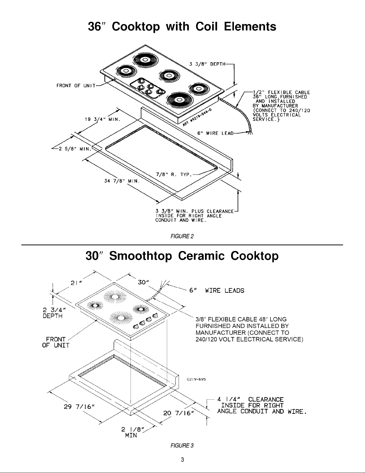
36" Cooktop with Coil Elements
r2" FLEXIBLE CABLE
AND INSTALLED
BY MANUFACTURER
(CONNECT TO 240/120
19 MIN.
6" WIRE LEAE
34 7/8" M IN.
VOLTS ELECTRICAL
SERVICE.)
LONG,FURNISHED
2 3/4"
DEPTH
FRONT//
OF UNIT
3 3/8" MIN. PLUS CLEARANCE
INSIDE FOR RIGHT ANGLE
CONDUIT AND WIRE.
FIGURE2
30" Smoothtop Ceramic Cooktop
6" WIRE LEADS
3/8" FLEXIBLE CABLE 48" LONG
FURNISHED AND INSTALLED BY
MANUFACTURER (CONNECT TO
240/120 VOLT ELECTRICAL SERVICE)
29 7/16"
2 I/8"
MIN
20 7/16"
RGURE3
4 I/4" CLEARANCE
INSIDE FOR RIGHT
ANGLE CONDUIT AND WIRE.
 Loading...