

Jenn-Air JED8130ADB17, JED8230ADB16, JED8345ADB16 Installation Guide
30" (76.2 CM) AND 45" (114.3 CM) ELECTRIC
DOWNDRAFT COOKTOP INSTALLATION INSTRUCTIONS
INSTRUCTIONS D’INSTALLATION DE LA TABLE DE
CUISSON ÉLECTRIQUE AVEC ASPIRATION PAR LE BAS DE
30" (76,2 CM) ET 45" (114,3 CM)
Table of Contents/Table des matières
COOKTOP SAFETY........................................................................1
INSTALLATION REQUIREMENTS ................................................2
Tools and Parts ............................................................................2
Location Requirements ................................................................2
Venting Requirements..................................................................4
Venting Methods ..........................................................................5
Electrical Requirements ..............................................................7
INSTALLATION INSTRUCTIONS ..................................................8
Prepare Cooktop..........................................................................8
Rotate Blower - Optional..............................................................9
Install Cooktop ...........................................................................10
Make Electrical Connection .......................................................10
Complete Installation..................................................................11
SÉCURITÉ DE LA TABLE DE CUISSON .................................13
EXIGENCES D'INSTALLATION................................................13
Outillage et pièces...................................................................13
Exigences d’emplacement......................................................13
Exigences concernant l'évacuation ........................................16
Méthodes d'évacuation...........................................................17
Spécifications électriques .......................................................19
INSTRUCTIONS D’INSTALLATION .........................................20
Préparation de la table de cuisson .........................................20
Rotation du ventilateur - Facultative.......................................20
Installation de la table de cuisson...........................................21
Raccordement électrique........................................................21
Achever l'installation ...............................................................23
COOKTOP SAFETY
Your safety and the safety of others are very important.
We have provided many important safety messages in this manual and on your appliance. Always read and obey all safety
messages.
This is the safety alert symbol.
This symbol alerts you to potential hazards that can kill or hurt you and others.
All safety messages will follow the safety alert symbol and either the word “DANGER” or “WARNING.”
These words mean:
You can be killed or seriously injured if you don't immediately
DANGER
WARNING
All safety messages will tell you what the potential hazard is, tell you how to reduce the chance of injury, and tell you what can
happen if the instructions are not followed.
IMPORTANT:
Save for local electrical inspector's use.
IMPORTANT :
À conserver pour consultation par l'inspecteur local des installations électriques.
W10298937B
follow instructions.
can be killed or seriously injured if you don't
You
instructions.
follow
INSTALLATION REQUIREMENTS
Tools and Parts
Gather the required tools and parts before starting installation.
Read and follow the instructions provided with any tools listed
here.
Tools needed
■ Tape measure
■ Flat-blade screwdriver
■ Phillips head screwdriver
■ Drill
■ Level
■ 6" socket extension
Parts supplied
■ Vent grille
■ Grease filter
■ Grill cartridge
■ Grease container(s)
■ Hold-down straps (4)
■ Clamping screws (4)
Parts needed
■ A UL listed or CSA approved strain relief for ⁷⁄₈"(2.2cm)
knockout.
■ A UL listed or CSA approved conduit connector for
¹⁄₂" (1.3 cm) trade-size metal-clad conduit
■ UL listed wire connectors
■ Metal ducting
■ Jenn-Air wall cap
®
Jenn-Air
Order Part Number A406
Jenn-Air
Order Part Number A403
To order, see the “Assistance or Service” section of the Use
and Care Guide.
■ Vent clamps
Check local codes. Check existing electrical supply. See
“Electrical Requirements” section.
It is recommended that all electrical connections be made by a
licensed, qualified electrical installer.
6" (15.2 cm) Round Surface Wall Cap Damper
®
3¼" x 10" (8.3 x 25.4 cm) Surface Wall Cap Damper
■ Marker or pencil
■ Pliers
■ ¼" drill bit
■ Jigsaw
■ Ratchet with ³⁄₈" socket
■ Use the countertop opening dimensions that are given with
these Installation Instructions. Given dimensions are
minimum clearances and provide 0" (0 cm) clearance.
■ Grounded electrical supply is required. See “Electrical
Requirements” section.
■ If cabinet has drawers, drawers will need to be removed and
drawer fronts installed on front of cabinet.
IMPORTANT: An under-counter built-in oven cannot be installed
under this product.
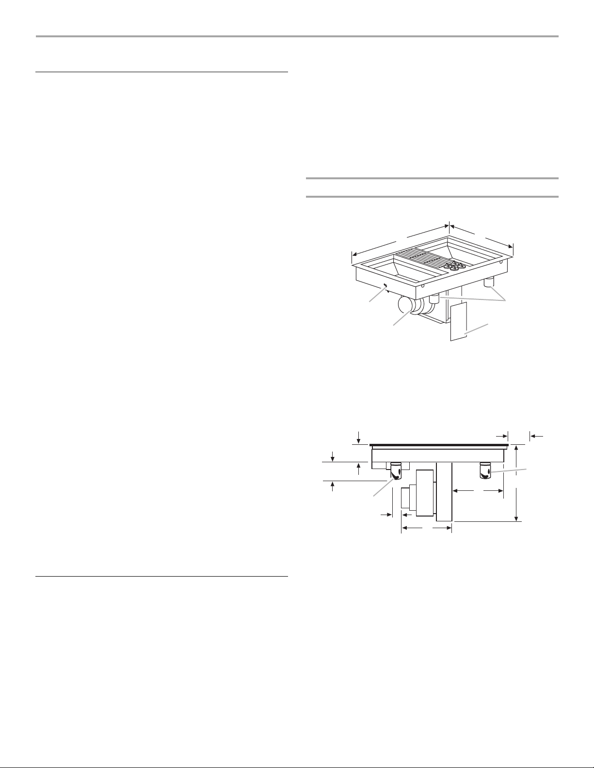
Product Dimensions
30" (76.2 cm) Cooktop
C
D
E
G
C
H
F
A
A. Tie down bolt (on each side of cookop)
B. 30" (76.2 cm)
C. 21³⁄₄" (55.3 cm)
D. Grease containers
E. Wiring box cover
F. B l ow e r
B
A*
C
D**
A. 6¹⁄₄" (15.9 cm)
B. 3¹⁄₂" (8.9 cm)
C. Grease containers
D. 2" (5.1 cm)
B
F
E
E. 13³⁄₄" (34.9 cm)
F. 1 1 ¹³⁄₁₆" (30.0 cm)
G. 4" (10.2 cm)
H. 13¹³⁄₁₆" (35.1 cm)
Location Requirements
IMPORTANT: Observe all governing codes and ordinances.
When installing cooktop, use minimum dimensions given.
■ To eliminate the risk of burns or fire by reaching over the
heated surface units, cabinet storage space located above
the surface units should be avoided. If cabinet storage is to
be provided, the risk can be reduced by installing a range
hood that projects horizontally a minimum of 5" (12.7 cm)
beyond the bottom of the cabinets.
2
*A minimum clearance of 6¹⁄₄" (15.9 cm) is recommended for
removal of the grease containers. Installed dimension for the
grease containers is 5¹⁄₂" (14.0 cm).
**A minimum clearance of 2" (5.1 cm) is recommended between
the motor/blower and cabinet for proper cooling.
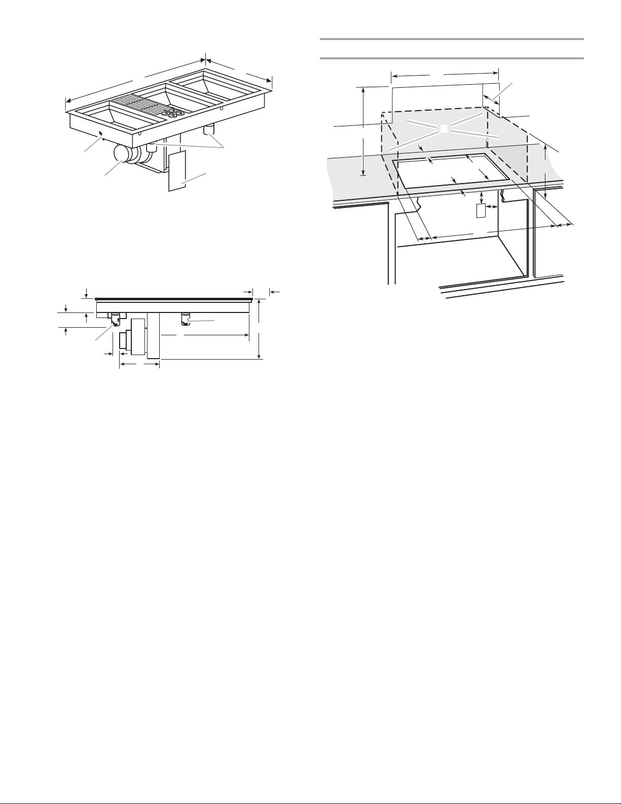
45" (114.3 cm) Cooktop
Cabinet Dimensions
B
A
F
A. Tie down bolt (on each side of cookop)
B. 45" (114.3 cm)
C. 21³⁄₄" (55.3 cm)
D. Grease containers
E. Wiring box cover
F. B l o w er
C
D
E
G
B
A*
F
C
H
C
D**
E
A. 6¹⁄₄" (15.9 cm)
B. 3¹⁄₂" (8.9 cm)
C. Grease containers
D. 2" (5.1 cm)
E. 13³⁄₄" (34.9 cm)
F. 2 6 ³⁄₄" (68.0 cm)
G. 4" (10.2 cm)
H. 13¹¹⁄₁₆" (35.1 cm)
*A minimum clearance of 6¹⁄₄" (15.9 cm) is recommended for
removal of the grease containers. Installed dimension for the
grease containers is 5¹⁄₂" (14.0 cm).
**A minimum clearance of 2" (5.1 cm) is recommended between
the motor/blower and cabinet for proper cooling.
A
D
C
B
L
F
E
G
H
I
K
A. 30" (76.2 cm) on 30" (76.2 cm) models
45" (114.3 cm) on 45" (114.3 cm) models
B. Combustible area above countertop (shown by dashed box above)
C. 30" (76.2 cm) minimum clearance between top of cooktop platform
and bottom of uncovered wood or metal cabinet (24" [61 cm]
minimum clearance if bottom of wood or metal cabinet is covered
by not less than ¹⁄₄" [0.6 cm] flame retardant millboard covered with
not less than No. 28 MSG sheet steel, 0.015" [0.04 cm] stainless
steel, or 0.024" [0.06 cm] aluminum or 0.020" [0.05 cm] copper)
D. 13" (33 cm) recommended upper cabinet depth
E. 1⁷⁄₈" (4.8 cm) min.
F. 21" (53.3 cm)
G. 18" (45.7 cm) minimum clearance from upper cabinet to countertop
within minimum horizontal clearances to cooktop
H. Junction box or outlet; 12" (30.5 cm) minimum from bottom of
countertop
I. Junction box or outlet; 10" (25.4 cm) from right-hand side of
cabinet
J. 29¹⁄₁₆" (73.9 cm) on 30" (76.2 cm) models
43¹⁄₄" (109.9 cm) on 45" (114.3 cm) models
K. 2½" (6.4 cm) minimum distance to nearest left and right side
combustible surface above cooktop
L. 1½" (3.8 cm) minimum clearance between back wall and
countertop
J
3
NOTES: After making the countertop cutout, some installations
may require notching down the base cabinet side walls to clear
the cooktop base. To avoid this modification, use a base cabinet
with sidewalls wider than the cutout.
■ Where possible, a 6" (15.2 cm) clearance is recommended for
motor blower service. A minimum clearance of 1" (2.5 cm) is
recommended to the sidewalls and a ³⁄₄" (1.9 cm) clearance is
recommended to the rear wall.
■ A minimum clearance of 2" (5.1 cm) is recommended
between the motor/blower and cabinet for proper cooling.
■ A minimum clearance of 6¹⁄₄" (15.9 cm) is recommended for
removal of the grease container(s). Installed dimension for the
grease containers is 5¹⁄₂" (14.0 cm).
■ For grills installed near a sidewall, a minimum clearance of
6" (15.2 cm) is recommended between the cooktop and
sidewall for maximum performance.
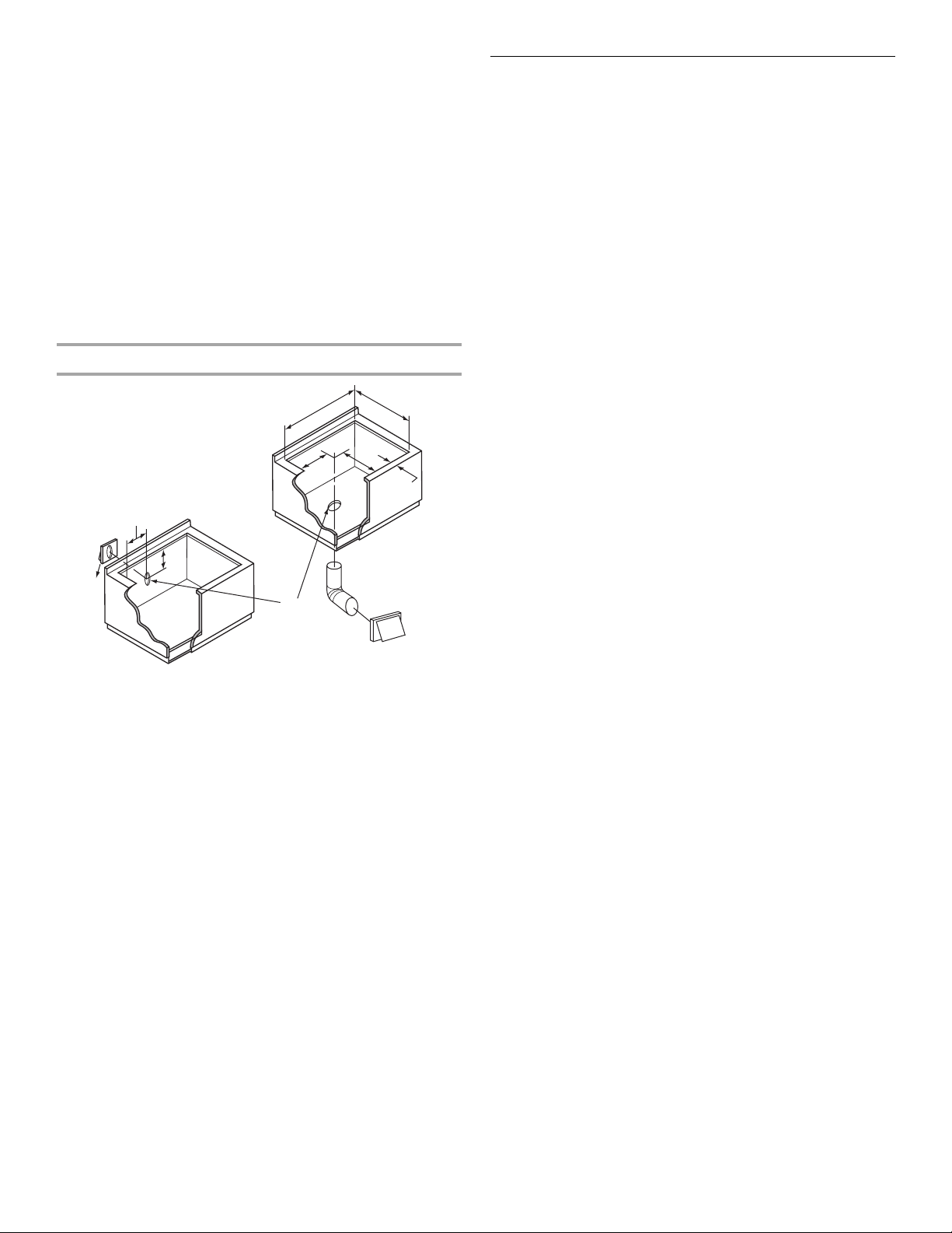
Cutout Dimensions
A
C
H
I
J
G
A. 29" ± ¹⁄₁₆" (73.6 cm ± 0.2 cm) on 30" (76.2 cm) models
43¹⁄₄" ± ¹⁄₁₆" (109.9 cm ± 0.2 cm) on 45" (114.3 cm) models
B. 21" ± ¹⁄₁₆" (53.3 cm ± 0.2 cm) maximum on both 30" (76.2 cm) and
45" (114.3 cm) models
C. 9³⁄₈" (23.8 cm) on both 30" (76.2 cm) models and 45" (114.3 cm)
models
D. 7⁹⁄₁₆" (19.2 cm) on both 30" (76.2 cm) and 45" (114.3 cm) models
E. 1⁷⁄₈" (4.8 cm) minimum space to front edge of cooktop
F. Floor exhaust option
G. 6¹⁄₈" (15.6 cm) for 6" vent system
H. 9³⁄₈" (21.9 cm) on both 30" (76.2 cm) and 45" (114.3 cm) models
I. 13" (33.0 cm) on both 30" (76.2 cm) and 45" (114.3 cm) models
J. Wall exhaust option
B
D
E
F
Venting Requirements
■ Do not terminate the vent system in an attic or other enclosed
area.
■ Use a Jenn-Air
■ Vent system must terminate to the outside.
■ Use only a 6" (15.2 cm) round metal vent. Rigid metal vent is
recommended. For best performance, do not use plastic or
metal foil vent.
■ Before making cutouts, make sure there is proper clearance
within the wall or floor for the exhaust vent.
■ Do not cut a joist or stud unless absolutely necessary. If a
joist or stud must be cut, then a supporting frame must be
constructed.
■ The size of the vent should be uniform.
■ The vent system must have a damper. If roof or wall cap has a
damper, do not use damper supplied with the range hood.
■ Use only a 6" (15.2 cm) round metal vent or a 3¹⁄₄" x 10"
(8.3 x 25.4 cm) rectangular metal vent except for as follows:
■ For electric models, 5" (12.7 cm) diameter round metal
vent may be used for venting straight out the back of the
cooktop and directly through the wall for a duct length of
10 ft (3.0 m) feet or less.
■ For gas models, 5" (12.7 cm) diameter round metal vent
must be used if the duct length is 10 ft (3.0 m) feet or less.
■ Do not use 5" (12.7 cm) elbows except in a 5" (12.7 cm)
system. Instead, use a 5" (12.7 cm) to 6" (15.2 cm) elbow or a
5" (12.7 cm) to 3¹⁄₄" x 10" (8.3 x 25.4 cm) elbow transition.
■ Use vent clamps to seal all joints in the vent system.
■ Use caulking to seal exterior wall or roof opening around the
cap.
■ Determine which venting method is best for your application.
For Best Performance:
■ Use 26-gauge minimum galvanized or 25-gauge minimum
aluminum metal vent. Poor quality pipe fittings can reduce
airflow. Flexible metal vent is not recommended.
NOTE: Local codes may require a heavier gauge material.
■ Metal duct may be reduced to 30-gauge galvanized steel or
26-gauge aluminized steel if allowed by local codes. This
reduction is based on information in the International
Residential Codes Section M1601.1 (2006 edition).
■ Do not install 2 elbows together.
■ Use no more than three 90° elbows.
■ If an elbow is used, install it as far away as possible from the
hood’s vent motor exhaust opening.
®
vent cap.
4
 Loading...