

Jenn-Air JED8130AD, JED8230AD, JED8345AD Product Dimensions
30" (76.2 CM) AND 45" (114.3 cm) ELECTRIC
DOWNDRAFT COOKTOP
PRODUCT MODEL NUMBERS CUTOUT DIMENSIONS
JED8130AD JED8230AD JED8345AD
Before You Make the Electrical Connection:
To properly install your cooktop, you must determine the type of electrical
connection you will be using and follow the instructions provided for it here.
●
A 4-wire or 3-wire, single phase, 120/240 volt, 60 Hz., AC only electrical
supply is required on a separate, 40-amp circuit (45" [114.3 cm] models) or
40-amp circuit (30" [76.2 cm] models), fused on both sides of the line.
●
The cooktop should be connected directly to the junction box in the cabinet
through the flexible metal conduit. The flexible, armored cable extending from
the fuse box or circuit breaker box should be connected directly to the
cooktop wiring box.
●
Locate the junction box in the cabinet to allow as much slack as possible
between the junction box and the cooktop so that the cooktop can be moved if
servicing becomes necessary in the future.
●
A UL listed or CSA approved conduit connector must be provided at each end
of the power supply cable (at the cooktop wiring box and at the junction box
in the cabinet).
●
If the house has aluminum wiring follow the procedure below:
1. Connect a section of solid copper wire to the pigtail leads.
2. Connect the aluminum wiring to the added section of copper wire using
special connectors and/or tools designed and UL listed for joining copper to
aluminum.
Follow the electrical connector manufacturer's recommended procedure.
Aluminum/copper connection must conform with local codes and industry
accepted wiring practices.
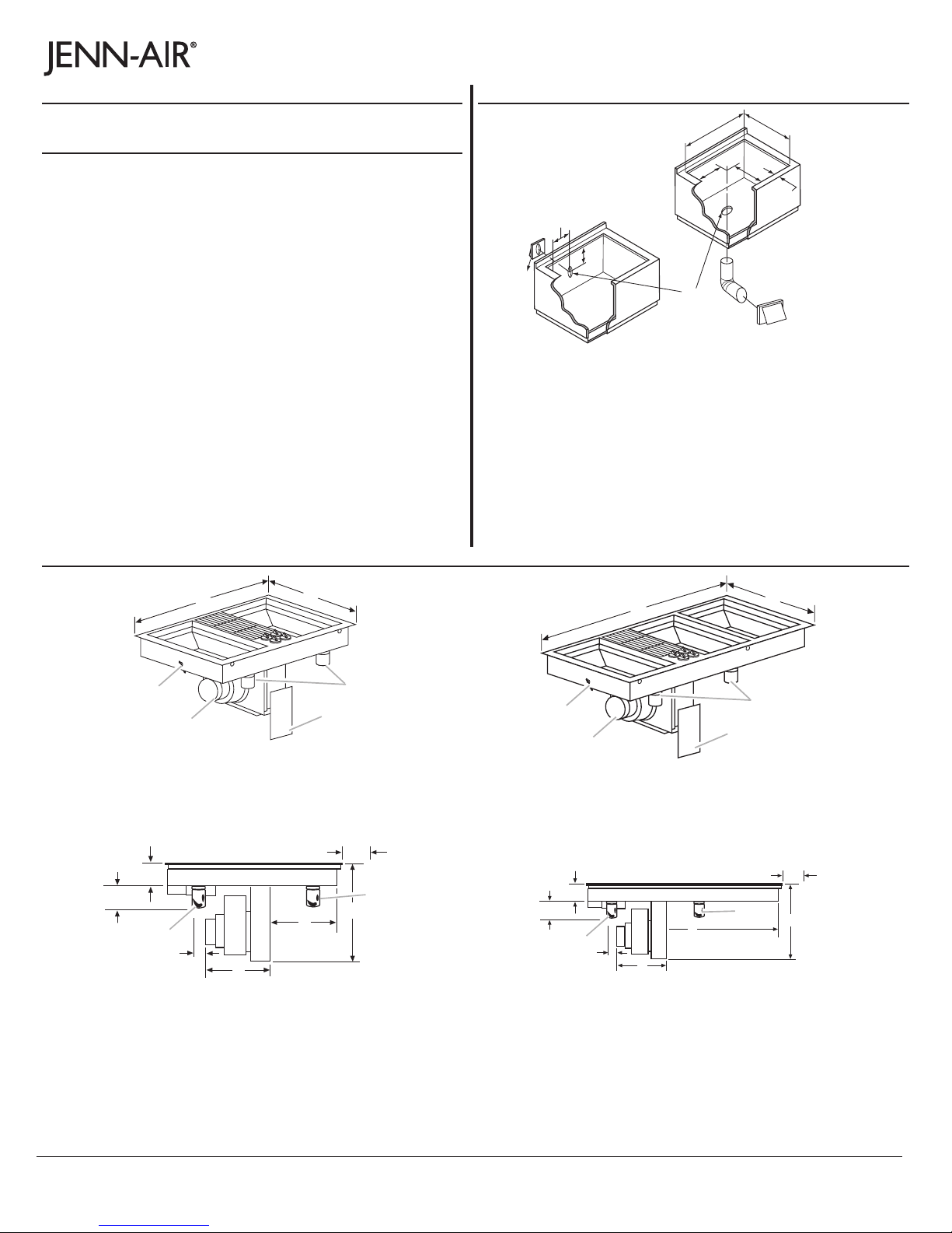
PRODUCT DIMENSIONS
ELECTRICAL REQUIREMENTS:
Because Whirlpool Corporation policy includes a continuous commitment to improve
our products, we reserve the right to change materials and specifications without notice.
Dimensions are for planning purposes only. For complete details, see Installation
Instructions packed with product. Specifications subject to change without notice.
Ref. W10298937B
2/24/12
Page 1 of 2
30" (76.2 cm) Cooktop
B
C
A
C
B
D
E
F
H
I
J
A. 29" ± ¹⁄₁₆" (73.6 cm ± 0.2 cm) on 30" (76.2 cm) models
43¹⁄₄" ± ¹⁄₁₆" (109.9 cm ± 0.2 cm) on 45" (114.3 cm) models
B. 21" ± ¹⁄₁₆" (53.3 cm ± 0.2 cm) maximum on both 30" (76.2 cm) and
45" (114.3 cm) models
C. 9 ³⁄₈" (23.8 cm) on both 30" (76.2 cm) models and 45" (114.3 cm)
models
D. 7 ⁹⁄₁₆" (19.2 cm) on both 30" (76.2 cm) and 45" (114.3 cm) models
E. 1⁷⁄₈" (4.8 cm) minimum space to front edge of cooktop
F. Floor exhaust option
G. 6¹⁄₈" (15.6 cm) for 6" vent system
H. 9 ³⁄₈" (21.9 cm) on both 30" (76.2 cm) and 45" (114.3 cm) models
I. 13" (33.0 cm) on both 30" (76.2 cm) and 45" (114.3 cm) models
J. Wall exhaust option
G
45" (114.3 cm) Cooktop
B
C
A
F
A. Tie down bolt (on each side of cookop)
B. 30" (76.2 cm)
C. 21³⁄₄" (55.3 cm)
D. Grease containers
E. Wiring box cover
F. B l ow e r
D
E
G
B
A*
C
F
C
H
D**
E
A. 6¹⁄₄" (15.9 cm)
B. 3¹⁄₂" (8.9 cm)
C. Grease containers
D. 2" (5.1 cm)
E. 13³⁄₄" (34.9 cm)
F. 1 1 ¹³⁄₁₆" (30.0 cm)
G. 4" (10.2 cm)
H. 13¹³⁄₁₆" (35.1 cm)
*A minimum clearance of 6¹⁄₄" (15.9 cm) is recommended for
removal of the grease containers. Installed dimension for the
grease containers is 5¹⁄₂" (14.0 cm).
**A minimum clearance of 2" (5.1 cm) is recommended between
the motor/blower and cabinet for proper cooling.
A
F
A. Tie down bolt (on each side of cookop)
B. 45" (114.3 cm)
C. 21³⁄₄" (55.3 cm)
D. Grease containers
E. Wiring box cover
F. B l o w er
D
E
B
A*
C
F
D**
C
E
A. 6¹⁄₄" (15.9 cm)
B. 3¹⁄₂" (8.9 cm)
C. Grease containers
D. 2" (5.1 cm)
E. 13³⁄₄" (34.9 cm)
F. 2 6 ³⁄₄" (68.0 cm)
G. 4" (10.2 cm)
H. 13¹¹⁄₁₆" (35.1 cm)
*A minimum clearance of 6¹⁄₄" (15.9 cm) is recommended for
removal of the grease containers. Installed dimension for the
grease containers is 5¹⁄₂" (14.0 cm).
**A minimum clearance of 2" (5.1 cm) is recommended between
the motor/blower and cabinet for proper cooling.
G
H
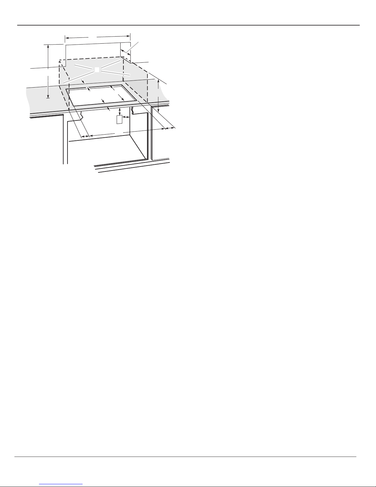
CABINET DIMENSIONS
NOTES: After making the countertop cutout, some installations may
require notching down the base cabinet side walls to clear the cooktop
base. To avoid this modification, use a base cabinet with sidewalls wider
than the cutout.
●
Where possible, a 6" (15.2 cm) clearance is recommended for motor
blower service. A minimum clearance of 1" (2.5 cm) is recommended to
the sidewalls and a ³⁄₄" (1.9 cm) clearance is recommended to the rear
wall.
●
A minimum clearance of 2" (5.1 cm) is recommended between the
motor/blower and cabinet for proper cooling.
●
A minimum clearance of 6¹⁄₄" (15.9 cm) is recommended for removal of
the grease container(s). Installed dimension for the grease containers is
5¹⁄₂" (14.0 cm).
●
For grills installed near a sidewall, a minimum clearance of 6" (15.2 cm)
is recommended between the cooktop and sidewall for maximum
performance.
Because Whirlpool Corporation policy includes a continuous commitment to improve
our products, we reserve the right to change materials and specifications without notice.
Dimensions are for planning purposes only. For complete details, see Installation
Instructions packed with product. Specifications subject to change without notice.
Ref. W10298937B
2/24/12
Page 2 of 2
A
D
C
B
L
F
E
G
H
I
K
A. 30" (76.2 cm) on 30" (76.2 cm) models
45" (114.3 cm) on 45" (114.3 cm) models
B. Combustible area above countertop (shown by dashed box above)
C. 30" (76.2 cm) minimum clearance between top of cooktop platform
and bottom of uncovered wood or metal cabinet (24" [61 cm]
minimum clearance if bottom of wood or metal cabinet is covered
by not less than ¹⁄₄" [0.6 cm] flame retardant millboard covered with
not less than No. 28 MSG sheet steel, 0.015" [0.04 cm] stainless
steel, or 0.024" [0.06 cm] aluminum or 0.020" [0.05 cm] copper)
D. 13" (33 cm) recommended upper cabinet depth
E. 1⁷⁄₈" (4.8 cm) min.
F. 21" (53.3 cm)
G. 18" (45.7 cm) minimum clearance from upper cabinet to countertop
within minimum horizontal clearances to cooktop
H. Junction box or outlet; 12" (30.5 cm) minimum from bottom of
countertop
I. Junction box or outlet; 10" (25.4 cm) from right-hand side of
cabinet
J. 29¹⁄₁₆" (73.9 cm) on 30" (76.2 cm) models
43¹⁄₄" (109.9 cm) on 45" (114.3 cm) models
K. 2½" (6.4 cm) minimum distance to nearest left and right side
combustible surface above cooktop
L. 1½" (3.8 cm) minimum clearance between back wall and
countertop
J
 Loading...