

Page 1
Outdoor Grill m'JENN-AIR |
Model _€" D IF_ 3 o 4o3ms, FouR,.STREE,NORT.NEV_O,_,A_0208j
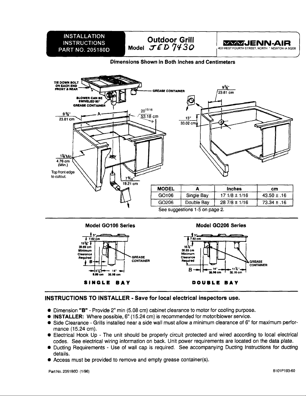
Dimensions Shown in Both Inches and Centimeters
I9.21 ¢m
MODEL A Inches
GO106 Single Bay 17 1/8 -+ 1/16
GO206 Double Bay 28 7/8 + 1/16
cm
43.50 + .16
73.34 +.16
See suggestions I-5 on page 2.
Model GO106 Series
_.egcm I I _| I
MJ._m.mI II I! 71"-.,.I
Clearance I I _-I I II "'__
c,....._. II _I LJ _'_N
Model GO206 Series
2cm I"
_L=J--_ co_,,,,,
SINGLE BAY
DOUIIILE BAY
INSTRUCTIONS TO INSTALLER - Save for local electrical inspectors use.
• Dimension "B" - Provide 2" min (5.08 cm) cabinet clearance to motor for cooling purpose.
• INSTALLER: Where possible, 6'! (15.24 cm) is recommended for motor/blower service.
• Side Clearance - Grills installed near a side wal! must allow a minimum clearance of 6" for maximum perfor-
mance (15.24 cm).
• Electrical Hook Up - The unit should be properly circuit protected and wired according to local electrical
codes. See electrical wiring information on back. Unit power requirements are located on the data plate.
• Ducting Requirements - Use of wall cap is required. See accompanying Ducting Instructions for ducting
details.
• Access must be provided to remove and empty grease container(s).
PartNo. 205180D (1/96) 8t01 P193-60
Page 2
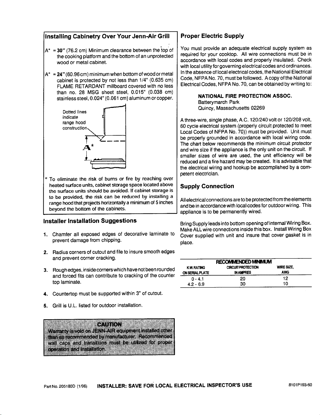
Installing Cabinetry Over Your Jenn-Air Grill
Proper Electric Supply
A* = 30" (76.2 cm) Minimum clearance between the top of
the cooking platform and the bottom of an unprotected
wood or metal cabinet.
A* = 24" (60.96 cm) minimum whenbottom of wood or metal
cabinet is protected by not less than 1/4" (0.635 cm)
FLAME RETARDANT millboard covered with no less
than no. 28 MSG sheet steel, 0.015" (0.038 cm)
stainlesssteel, 0.024" (0.061 cm) aluminum or copper.
Dottedlines
indicate II
range hood II
c°nstructi°_.._,%__/L._.._
[ •....
J_'i '''A_ '"!!!!!_T
i
To eliminate the risk of burns or fire by reaching over
heated surface units, cabinet storage space located above
the surface units should be avoided, If cabinet storage is
to be provided, the risk can be reduced by installing a
range hood that projects horizontally a minimum of 5 inches
beyond the bottom of the cabinets,
Installer Installation Suggestions
1. Chamfer all exposed edges of decorative laminate to
prevent damage from chipping.
2. Radius cornersof cutout and file to insure smooth edges
and prevent corner cracking.
3. Roughedges, insidecomerswhichhavenotbeenrounded
and forced fits can contribute to cracking of the counter
top laminate.
You must provide an adequate electrical supply system as
required for your cooktop. All wire connections must be in
accordance with local codes and properly insulated. Check
with local utilityfor governing e}ectrical codes and ordinances.
tnthe absence oflocal electrical codes, the National Electrical
Code, NFPA No. 70, must befollowed. A copy of the National
Electrical Codes, NFPA No. 70, can beobtained bywriting to:
NATIONAL FIRE PROTECTION ASSOC.
BatterymarchPark
Quincy, Massachusetts 02269
A three-wire, single phase, A.C. 120/240 volt or 120/208 volt,
60 cycle electrical system (properly circuit protected to meet
Local Codes of NFPA NO.70)) must be provided. Unit must
be properly grounded inaccordance with local wiring code.
The chart below recommends the minimum circuit protector
and wire size if the appliance is the only unit on the circuit. If
smaller sizes of wire are used, the unit efficiency wilt be
reduced and afire hazard may be created. It is advisable that
the electrical wiring and hookup be accomplished by a com-
petent electrician.
Supply Connection
Allelectrical connections are tobe protected from the elements
and be inaccordance with local codes for outdoor wiring. This
appliance is to be permanently wired.
Bring Supply leads intobottom opening ofinternal Wiring Box.
Make ALL wire connections inside this box. Install Wiring Box
Cover supplied with unit and insure that cover gasket is in
place.
_MIMMI._
K.W.RATING CIRC_PROTECTION _ SIZE,
ONSERIALPLATE INAMPRES AWG
0 - 4.1 20 !2
4.2 - 6.9 30 10
4. Counter'top must be supported within 3" of cutout.
5. Grill is U.L. listed for outdoor installation.
PartNo.205180D(1/96) INSTALLER: SAVE FoR LOCAL ELECTRICAL INSPECTOR'S USE 8!01P193-60
 Loading...