

Jenn-Air JED3430WB00, JED3430WF00, JED3430WS00, JED3536WB00, JED3536WB01 Installation Guide
...
_]ENN-AIRo
30" (76.2 CM) AND 36" (91.4 CM) ELECTRIC
DOWNDRAFT COOKTOP INSTALLATION INSTRUCTIONS
INSTRUCTIONSD'INSTALLATIONDE LATABLEDE
CUISSON ELECTRIQUEAVEC ASPIRATIONPARLEBASDE
30" (76,2 CM) ET36" (91,4 CM)
Table of Contents/Table des mati_res
COOKTOP SAFETY ..................................................................................... 2
INSTALLATION REQUIREMENTS ............................................................. 3
Tools and Parts ......................................................................................... 3
Location Requirements ............................................................................. 3
Venting Requirements .............................................................................. 5
Venting Methods ....................................................................................... 6
Electrical Requirements ........................................................................... 7
INSTALLATION INSTRUCTIONS ............................................................... 8
Prepare Cooktop ....................................................................................... 8
Install Foam Strip ...................................................................................... 8
Rotate Blower ........................................................................................... 8
Install Cooktop ........................................................................................ 10
Make Electrical Connection .................................................................... 10
Complete Installation .............................................................................. 11
SI_CURITI_ DE LA TABLE DE CUISSON ............................................ 13
EXIGENCES D'INSTALLATION ........................................................... 14
Outillage et pieces ............................................................................. 14
Exigences d 'emplacement ................................................................ 14
Exigences concernant I'evacuation .................................................. 16
Methodes d '_vacuation ..................................................................... 17
Specifications electriques ................................................................. 18
INSTRUCTIONS D'INSTALLATION .................................................... 19
Pr6paration de la table de cuisson .................................................... 19
Installation de la bande de mousse .................................................. 19
Rotation du ventilateur ...................................................................... 20
Installation de la table de cuisson ..................................................... 21
Raccordement electrique .................................................................. 21
Achever I'installation .......................................................................... 22
iMPORTANT:
Save for local electrical inspector's use.
iMPORTANT :
,&,conserver pour consultation par I'inspecteur local des installations 61ectriques.
W10197059A
COOKTOP SAFETY
Your safety and the safety of others are very important.
We have provided many important safety messages in this manual and on your appliance. Always read and obey all safety
messages.
This is the safety alert symbol.
This symbol alerts you to potential hazards that can kill or hurt you and others.
All safety messages will follow the safety alert symbol and either the word "DANGER" or "WARNING."
These words mean:
You can be killed or seriously injured if you don't immediately
follow instructions.
You can be killed or seriously injured if you don't follow
instructions.
All safety messages will tell you what the potential hazard is, tell you how to reduce the chance of injury, and tell you what can
happen if the instructions are not followed.
2
INSTALLATIONREQUIREMENTS
Gather the required tools and parts before starting installation.
Read and follow the instructions provided with any tools listed
here.
Tools needed
• Tape measure
• Flat-blade screwdriver
• Phillips head screwdriver
• Drill
• Level
• 6" socket extension
Parts supplied
• Vent grille
• Pre-filter
Parts needed
• A UL listed or CSA approved strain relief for 7/8"(2.2 cm)
knockout.
• A UL Listed or CSA Approved conduct connector for 1/2"
(1.3 cm) trade size metal clad conduit
• UL listed wire connectors
• Metal ducting
• Jenn-Air wall cap
Jenn-Air®6" (15.2 cm) Round Surface Wall Cap Damper
Order Part Number A406
Jenn-Air ®31¼'' x 10" (8.3 x 25.4 cm) Surface Wall Cap Damper
Order Part Number A403
To order, see the "Assistance or Service" section of the Use
and Care Guide.
• Vent clamps
Check local codes. Check existing electrical supply. See
"Electrical Requirements."
It is recommended that all electrical connections be made by a
licensed, qualified electrical installer.
• Marker or pencil
• Pliers
• 1¼.drill bit
• Jigsaw
• Ratchet with 3/8"socket
IMPORTANT: Observe all governing codes and ordinances. When
installing cooktop, use minimum dimensions given.
• To eliminate the risk of burns or fire by reaching over the
heated surface units, cabinet storage space located above the
surface units should be avoided. If cabinet storage is to be
provided, the risk can be reduced by installing a range hood
that projects horizontally a minimum of 5" (12.7 cm) beyond
the bottom of the cabinets.
• Use the countertop opening dimensions that are given with
these Installation Instructions. Given dimensions are minimum
clearances and provide 0" (0 cm) clearance.
• Grounded electrical supply is required. See "Electrical
Requirements" section.
• If cabinet has drawers, drawers will need to be removed and
drawer fronts installed on front of cabinet.
IMPORTANT: An under-counter built-in oven cannot be installed
under this product.
Product Dimensions
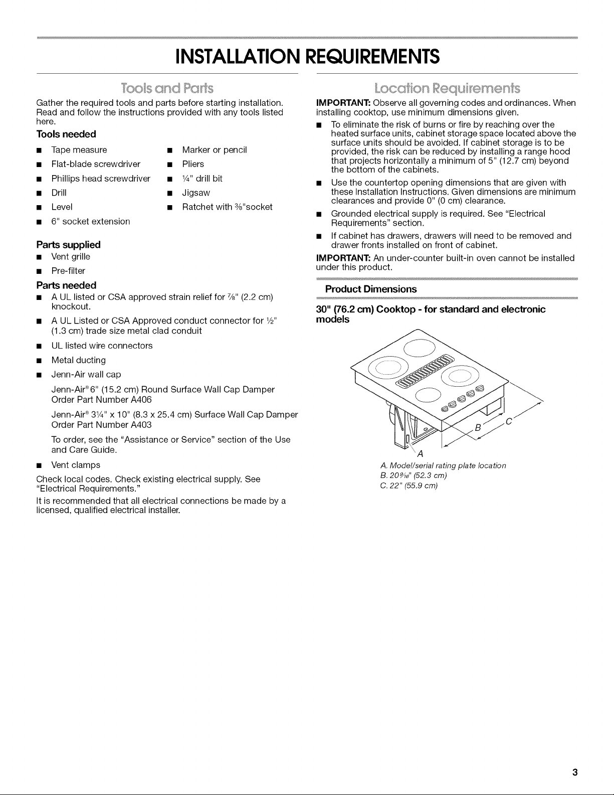
30" (76.2 cm) Cooktop - for standard and electronic
models
_A
A. Model/serial rating plate location
B. 20_d' (52.3 cm)
C. 22" (55.9 cm)
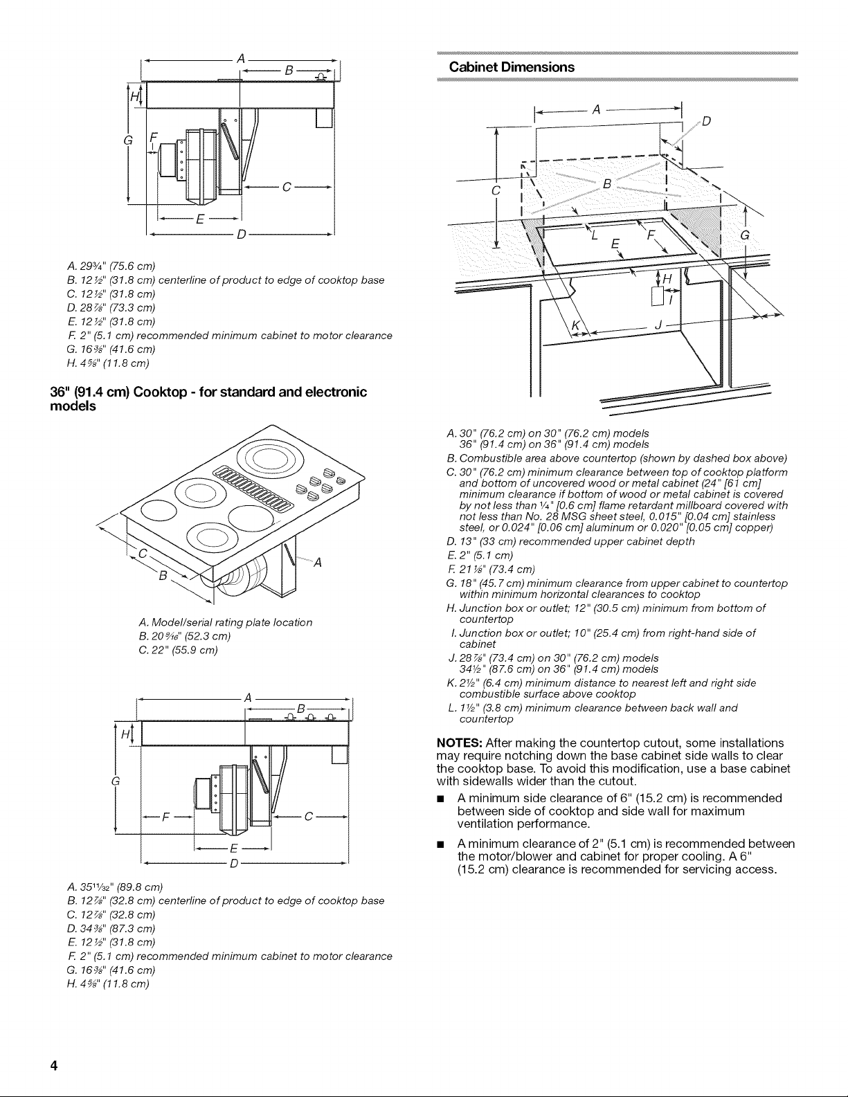
A.293/4" (75.6 cm)
B. 12 ½" (31.8 cm) centerline of product to edge of cooktop base
C. 12½" (31.8 cm)
D. 28 _" (73.3 cm)
E. 12½" (31.8 cm)
F. 2" (5.1 cm) recommended minimum cabinet to motor clearance
G. 16_" (41.6 cm)
H. 4_" (11.8 cm)
36" (91.4 cm) Cooktop - for standard and electronic
models
A. Model/serial rating plate location
B. 20_" (52.3 cm)
C. 22" (55.9 cm)
A
Cabinet Dimensions
C
A. 30" (76.2 cm) on 30" (76.2 cm) models
36" (91.4 cm) on 36" (91.4 cm) models
B. Combustible area above countertop (shown by dashed box above)
C. 30" (76.2 cm) minimum clearance between top of cooktop platform
and bottom of uncovered wood or metal cabinet (24" [61 cm]
minimum clearance if bottom of wood or metal cabinet is covered
by not less than 1/4"[0.6 cm] flame retardant millboard covered with
not less than No. 28 MSG sheet steel, 0.015" [0.04 cm] stainless
steel, or 0.024" [0.06 cm] aluminum or 0.020" [0.05 cm] copper)
D. 13" (33 cm) recommended upper cabinet depth
E.2"(5.1 cm)
F. 21 '_" (73.4 cm)
G. 18" (45. 7cm) minimum clearance from upper cabinet to countertop
within minimum horizontal clearances to cooktop
H. Junction box or outlet; 12" (30.5 cm) minimum from bottom of
countertop
I. Junction box or outlet; 10" (25.4 cm) from right-hand side of
cabinet
J. 28 z_,,(73.4 cm) on 30" (76.2 cm) models
34V2" (87.6 cm) on 36" (91.4 cm) models
K. 2V2" (6.4 cm) minimum distance to nearest left and right side
combustible surface above cooktop
L. 17/2"(3.8 cm) minimum clearance between back wall and
countertop
D
A. 3511/32 '' (89.8 cm)
B. 12 _" (32.8 cm) centerline of _roduct to edge of cooktop base
C. 12z_'' (32.8 cm)
D. 34_" (87.3 cm)
E. 12½" (31.8 cm)
F. 2" (5.1 cm) recommended minimum cabinet to motor clearance
G. 16_" (41.6 cm)
H. 4_" (11.8 cm)
NOTES: After making the countertop cutout, some installations
may require notching down the base cabinet side walls to clear
the cooktop base. To avoid this modification, use a base cabinet
with sidewalls wider than the cutout.
• A minimum side clearance of 6" (15.2 cm) is recommended
between side of cooktop and side wall for maximum
ventilation performance.
• A minimum clearance of 2" (5.1 cm) is recommended between
the motor/blower and cabinet for proper cooling. A 6"
(15.2 cm) clearance is recommended for servicing access.
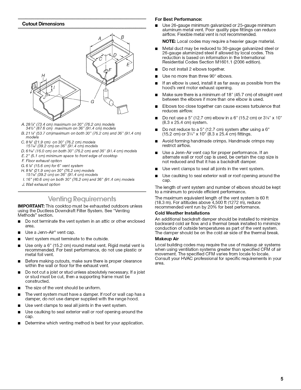
Cutout Dimensions
A
H
G
A. 28_" (73.4 cm) maximum on 30" (76.2 cm) models
34V2" (87.6 cm) maximum on 36" (91.4 cm) models
B. 21 _" (53.7 cm)maximum on both 30" (76.2 cm) and 36" (91.4 cm)
models
C. 8_" (21.9 cm) on 30" (76.2 cm) models
15zA_''(39.2 cm) on 36" (91.4 cm) models
D. 6_" (16.0 cm) on both 30" (76.2 cm) and 36" (91.4 cm) models
E. 2" (5.1 cm) minimum space to front edge of cooktop
F. Floor exhaust option
G. 6 _" (15.6 cm) for 6" vent system
H. 8_" (21.9 cm) on 30" (76.2 cm) models
15zA_''(39.2 cm) on 36" (91.4 cm) models
I. 16" (40.6 cm) on both 30" (76.2 cm) and 36" (91.4 cm) models
J. Waft exhaust option
IMPORTANT: This cooktop must be exhausted outdoors unless
using the Ductless Downdraft Filter System. See "Venting
Methods" section.
• Do not terminate the vent system in an attic or other enclosed
area.
• Use a Jenn-Air ®vent cap.
• Vent system must terminate to the outside.
• Use only a 6" (15.2 cm) round metal vent. Rigid metal vent is
recommended. For best performance, do not use plastic or
metal foil vent.
• Before making cutouts, make sure there is proper clearance
within the wall or floor for the exhaust vent.
• Do not cut a joist or stud unless absolutely necessary. Ifa joist
or stud must be cut, then a supporting frame must be
constructed.
• The size of the vent should be uniform.
• The vent system must have a damper. Ifroof or wall cap has a
damper, do not use damper supplied with the range hood.
• Use vent clamps to seal all joints in the vent system.
• Use caulking to seal exterior wall or roof opening around the
cap.
• Determine which venting method is best for your application.
B
For Best Performance:
• Use 26-gauge minimum galvanized or 25-gauge minimum
aluminum metal vent. Poor quality pipe fittings can reduce
airflow. Flexible metal vent is not recommended.
NOTE: Local codes may require a heavier gauge material.
• Metal duct may be reduced to 30-gauge galvanized steel or
26-gauge aluminized steel if allowed by local codes. This
reduction is based on information inthe International
Residential Codes Section M1601.1 (2006 edition).
• Do not install 2 elbows together.
• Use no more than three 90° elbows.
If an elbow is used, install it as far away as possible from the
hood's vent motor exhaust opening.
Make sure there is a minimum of 18" (45.7 cm) of straight vent
between the elbows if more than one elbow is used.
• Elbows too close together can cause excess turbulence that
reduces airflow.
Do not use a 5" (12.7 cm) elbow in a6" (15.2 cm) or 3V4"x 10"
(8.3 x 25.4 cm) system.
Do not reduce to a 5" (12.7 cm) system after using a 6"
(15.2 cm) or 31/4"x 10" (8.3 x 25.4 cm) fittings.
Avoid forming handmade crimps. Handmade crimps may
restrict airflow.
Use a Jenn-Air vent cap for proper performance. If an
alternate wall or roof cap is used, be certain the cap size is
not reduced and that it has a backdraft damper.
Use vent clamps to seal all joints in the vent system.
Use caulking to seal exterior wall or roof opening around the
cap.
The length of vent system and number of elbows should be kept
to a minimum to provide efficient performance.
The maximum equivalent length of the vent system is 60 ft
(18.3 m). For altitudes above 4,500 ft (1272 m), reduce
recommended vent run by 20% for best performance.
Cold Weather Installations
An additional backdraft damper should be installed to minimize
backward cold air flow and a thermal break installed to minimize
conduction of outside temperatures as part of the vent system.
The damper should be on the cold air side of the thermal break.
Makeup Air
Local building codes may require the use of makeup air systems
when using ventilation systems greater than specified CFM of air
movement. The specified CFM varies from locale to locale.
Consult your HVAC professional for specific requirements in your
area.
÷thods
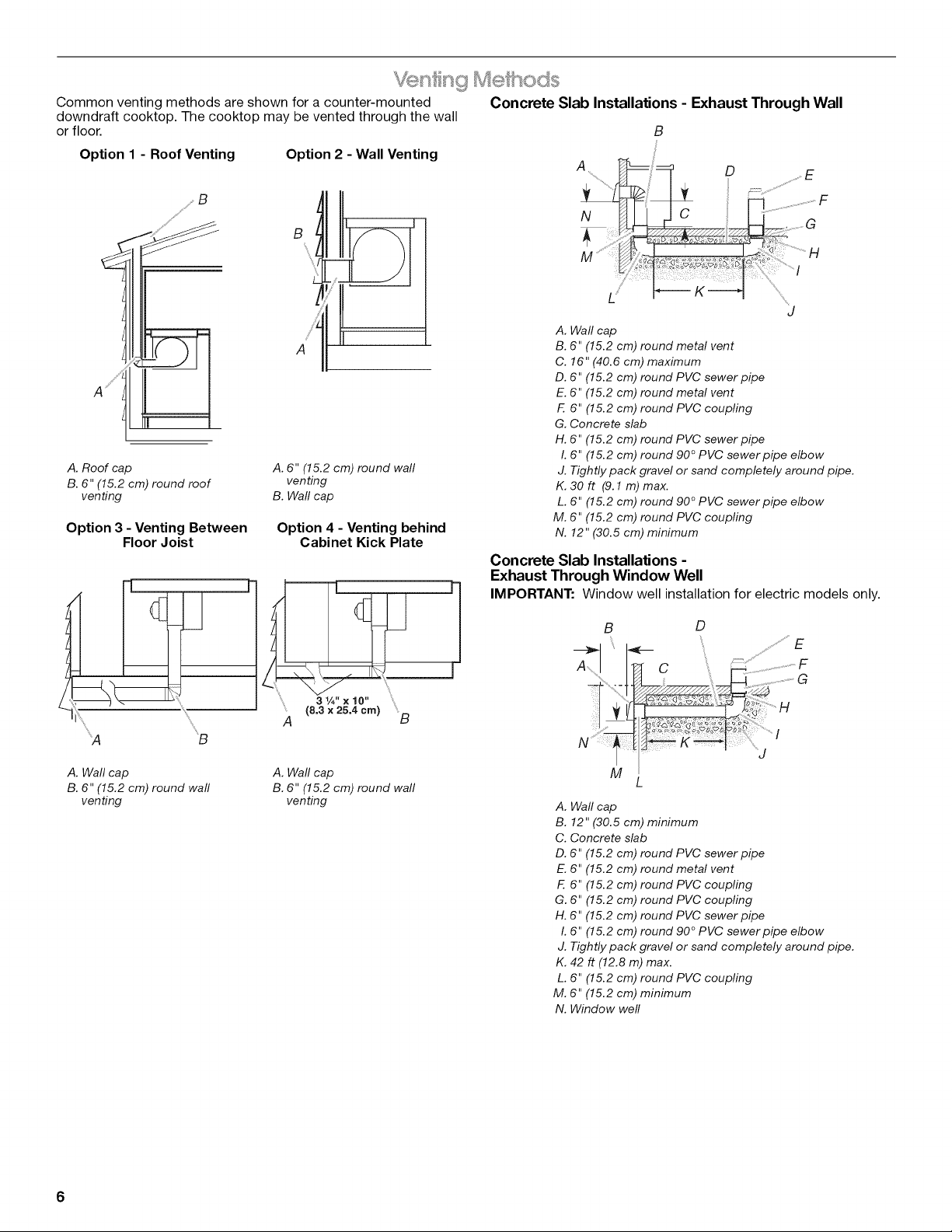
Common venting methods are shown for a counter-mounted Concrete Slab Installations - Exhaust Through Wall
downdraft cooktop. The cooktop may be vented through the wall
or floor. B
Option 1 - Roof Venting
_ g
Option 2 - Wall Venting
.... .....ilia!&¸ ............H
A. Roof cap
B. 6" (15.2 cm) round roof
venting
Option 3 - Venting Between
Floor Joist
'_A B
A
A. 6" (15.2 cm) round wall
venting
B. Wall cap
Option 4 - Venting behind
Cabinet Kick Plate
= " = "
...... K---"t ..........................
J
A. Wall cap
B. 6" (15.2 cm) round metal vent
C. 16" (40.6 cm) maximum
D. 6" (15.2 cm) round PVC sewer pipe
E. 6" (15.2 cm) round metal vent
F. 6" (15.2 cm) round PVC coupling
G. Concrete slab
H. 6" (15.2 cm) round PVC sewer pipe
I. 6" (15.2 cm) round 90 ° PVC sewer pipe elbow
J. Tightly pack gravel or sand completely around pipe.
K. 3Oft (9.1m) max.
L. 6" (15.2 cm) round 90 ° PVC sewer pipe elbow
M. 6" (15.2 cm) round PVC coupling
N. 12" (30.5 cm) minimum
Concrete Slab Installations -
Exhaust Through Window Well
IMPORTANT: Window well installation for electric models only.
B D
A. Wall cap
B. 6" (15.2 cm) round wall
venting
6
A. Wall cap
B. 6" (15.2 cm) round wall
venting
A. Wall cap
B. 12" (30.5 cm) minimum
C. Concrete slab
D. 6" (15.2 cm) round PVC sewer pipe
E. 6" (15.2 cm) round metal vent
F. 6" (15.2 cm) round PVC coupling
G. 6" (15.2 cm) round PVC coupling
H. 6" (15.2 cm) round PVC sewer pipe
I. 6" (15.2 cm) round 90 ° PVC sewer pipe elbow
J. Tightly pack gravel or sand completely around pipe.
K. 42 ft (12.8 m) max.
L. 6" (15.2 cm) round PVC coupling
M. 6" (15.2 cm) minimum
N. Window well
Jenn-Air e Duct Free Filter Accessory Kit
On select downdraft models, the Jenn-Air ® Duct Free Filter
Accessory Kit Part Number JDX7000WX is now available. The
Jenn-Air ®Duct Free Filter Accessory Kit is ideal for both new
construction and kitchen renovation projects because it provides
an easy alternative to the installation of metal ducting and venting
in the downdraft system outside the home. The kit includes all
required hardware, one filter and complete installation
instructions. For more information on the Jenn-Air ®Duct Free Filter
Accessory Kit, contact your Jenn-Air ®dealer or call
1-800-J ENNAI R (1-800-536-6247).
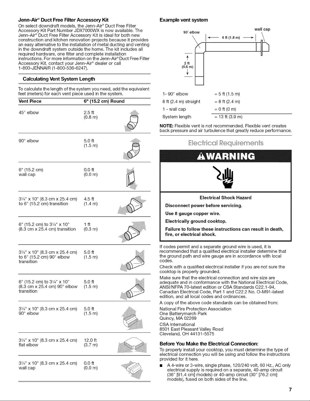
Calculating Vent System Length
Tocalculate the length of the system you need, add the equivalent
feet (meters) for each vent piece used in the system.
Vent Piece 6" (15.2 cm) Round
45° elbow 2.5 ft
(0.8m)
90° elbow 5.0 ft
(1.5m)
Example vent system
90" elbow
6ft (1.8m)
wall cap
,©
(
1- 90° elbow = 5 ft (1.5 m)
8 ft (2.4 m) straight = 8 ft (2.4 m)
1 - wall cap = 0 ft (0 m)
System length = 13 ft (3.9 m)
NOTE: Flexible vent is not recommended. Flexible vent creates
back pressure and air turbulence that greatly reduce performance.
6" (15.2 cm) 0.0 ft
wall cap (0.0 m)
31/4"x 10" (8.3 cm x 25.4 cm) 4.5 ft
to 6" (15.2 cm) transition (1.4 m)
6" (15.2 cm) to 31/4'' x 10" 1 ft
(8.3 cm x 25.4 cm) transition (0.3 m)
31/4"x 10" (8.3 cm x 25.4 cm) 5.0 ft
to 6" (15.2 cm) 90 ° elbow (1.5 m)
transition
6" (15.2 cm) to 31/4"x 10" 5.0 ft
(8.3 cm x 25.4 cm) 90° elbow (1.5 m)
transition
31/4"x 10" (8.3 cm x 25.4 cm) 5.0 ft
90° elbow (1.5 m)
31/4"x 10" (8.3 cm x 25.4 cm) 12.0 ft
flat elbow (3.7 m)
31/4'' x 10" (8.3 cm x 25.4 cm) 0.0 ft
wall cap (0.0 m)
Electrical Shock Hazard
Disconnect power before servicing.
Use 8 gauge copper wire.
Electrically ground cooktop.
Failure to follow these instructions can result in death,
fire, or electrical shock.
If codes permit and a separate ground wire is used, it is
recommended that a qualified electrical installer determine that
the ground path and wire gauge are in accordance with local
codes.
Check with a qualified electrical installer if you are not sure the
cooktop is properly grounded.
Make sure that the electrical connection and wire size are
adequate and in conformance with the National Electrical Code,
ANSl/NFPA 70-latest edition or CSA Standards C22.1-94,
Canadian Electrical Code, Part 1 and C22.2 No. O-M91-1atest
edition, and all local codes and ordinances.
A copy of the above code standards can be obtained from:
National Fire Protection Association
One Batterymarch Park
Quincy, MA 02269
CSA International
8501 East Pleasant Valley Road
Cleveland, OH 44131-5575
Before You Make the Electrical Connection:
To properly install your cooktop, you must determine the type of
electrical connection you will be using and follow the instructions
provided for it here.
• A 4-wire or 3-wire, single phase, 120/240 volt, 60 Hz., AC only
electrical supply is required on a separate, 40-amp circuit
(36" [91.4 cm] models) or 40-amp circuit (30" [76.2 cm]
models), fused on both sides of the line.
Thecooktopshouldbeconnecteddirectlytothejunctionbox •
throughtheflexiblemetalconduit.Theflexible,armoredcable
extendingfromthefuseboxorcircuitbreakerboxshouldbe 1.
connecteddirectlytothejunctionbox. 2.
Locatethejunctionboxtoallowasmuchslackaspossible
betweenthejunctionboxandthecooktopsothatthecooktop
canbemovedifservicingbecomesnecessaryinthefuture.
AULlistedorCSAapprovedconduitconnectormustbe
providedateachendofthepowersupplycable(atthe
cooktopandatthejunctionbox).
INSTALLATIONINSTRUCTIONS
Ifthehousehasaluminumwiringfollowtheprocedurebelow:
Connectasectionofsolidcopperwiretothepigtailleads.
Connectthealuminumwiringtotheaddedsectionofcopper
wireusingspecialconnectorsand/ortoolsdesignedandUL
listedforjoiningcoppertoaluminum.
Followtheelectricalconnectormanufacturer'srecommended
procedure.Aluminum/copperconnectionmustconformwith
localcodesandindustryacceptedwiringpractices.
Decide on the final location for the cooktop.
Excessive Weight Hazard
Use two or more people to move and install cooktop.
Failure to do so can result in back or other injury.
1. Open product as instructed on product packaging.
2. Remove shipping materials and tape from cooktop.
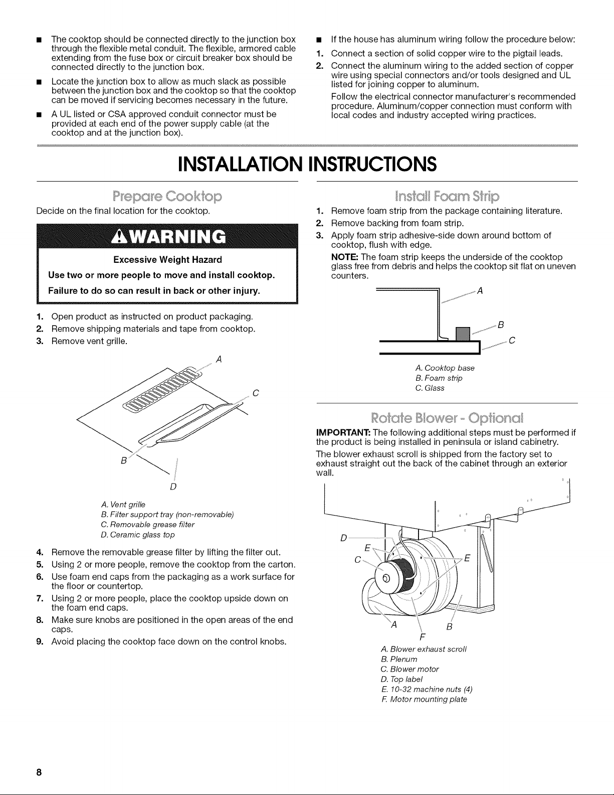
3. Remove vent grille.
A
D
A. Vent grille
B.Filter support tray (non-removable)
C. Removable grease filter
D. Ceramic glass top
4. Remove the removable grease filter by lifting the filter out.
5. Using 2 or more people, remove the cooktop from the carton.
6. Use foam end caps from the packaging as a work surface for
the floor or countertop.
7. Using 2 or more people, place the cooktop upside down on
the foam end caps.
8. Make sure knobs are positioned in the open areas of the end
caps.
9. Avoid placing the cooktop face down on the control knobs.
1.
Remove foam strip from the package containing literature.
2.
Remove backing from foam strip.
3.
Apply foam strip adhesive-side down around bottom of
cooktop, flush with edge.
NOTE: The foam strip keeps the underside of the cooktop
glass free from debris and helps the cooktop sit flat on uneven
counters.
A. Cooktop base
B. Foam strip
C. Glass
O G
IMPORTANT: The following additional steps must be performed if
the product is being installed in peninsula or island cabinetry.
The blower exhaust scroll is shipped from the factory set to
exhaust straight out the back of the cabinet through an exterior
wall.
00 e I
D
"A \ B
F
A. Blower exhaustscroll
B.Plenum
C. Blower motor
D. Top label
E. 10-32machine nuts (4)
F. Motor mounting plate
/
8
 Loading...