

Jenn-Air JDRP430HL00, JDRP430HM00, JDRP436HL00, JDRP436HM00 Installation Guide

INSTALLATION INSTRUCTIONS
CommerCial-Style Dual Fuel ConveCtion rangeS
30" (76.2 Cm), 36" (91.4 Cm), anD 48" (121.9 Cm)
For residential use only
INSTRUCTIONS D’INSTALLATION
CuiSinière à Double CombuStible à ConveCtion De Style CommerCial
De 30 po (76,2 Cm), 36 po (91,4 Cm) et 48 po (121,9 Cm)
Pour utilisation résidentielle uniquement
Table of Contents/Table des matières
RANGE SAFETY .............................................................................2
INSTALLATION REQUIREMENTS
Tools and Parts
Water Filtration System Location Requirements
Water Supply Requirements
Location Requirements
Electrical Requirements: U.S.A. Only
Electrical Requirements: CanadaOnly
Gas Supply Requirements
INSTALLATION INSTRUCTIONS
Unpack the Range
Remove Door
Install Anti-Tip Bracket
Make Gas Connection
Verify Anti-Tip Bracket Location
Install Griddle Tray
Electronic Ignition System
Level Range
Install Kick Plate
Complete Installation
GAS CONVERSIONS
Propane Gas Conversion
Natural Gas Conversion
.............................................................................4
................................................................6
.....................................................................10
.............................................................................11
...............................................................12
...............................................................13
......................................................................13
................................................................................14
.........................................................................15
.................................................................15
....................................................................16
.............................................................20
.................................................4
.........................5
........................................................5
..........................................8
........................................8
...........................................................8
.................................................10
................................................13
.........................................................14
...........................................................16
SÉCURITÉ DE LA CUISINIÈRE
EXIGENCES D’INSTALLATION
Outils et pièces
Exigences d’emplacement du système de ltration d’eau
Spécications de l’alimentationen eau
Exigences d’emplacement
Spécications électriques: É.-U. seulement
Spécications électriques: Canada seulement
Spécications de l’alimentationen gaz
INSTRUCTIONS D’INSTALLATION
Déballage de la cuisinière
Retirer la porte
Installation de la bride antibasculement
Raccordement au gaz
Vérication de l’emplacement dela bride antibasculement
Installer le plateau d’égouttement
Système d’allumage électronique..............................................37
Ajustement de l’aplomb delacuisinière
Installer la plinthe
Terminer l’installation
CONVERSIONS POUR CHANGEMENT DE GAZ
Conversion pour l’alimentation aupropane
Conversion au gaz naturel
...........................................................................26
............................................................................34
................................................................36
.......................................................................38
..................................................................38
...................................................24
...................................................26
.....................................28
.........................................................28
.............................30
........................31
.....................................31
.............................................33
..........................................................33
....................................35
.............................................36
....................................37
......................39
..............................39
.........................................................43
.......27
......36
IMPORTANT:
Save for local electrical inspector’s use.
Installer: Leave installation instructions with the homeowner.
Homeowner: Keep installation instructions for future reference.
IMPORTANT:
Conserver ces instructions à l’usage de l’inspecteur des installations électriques local.
Installateur: Remettre les instructions d’installation au propriétaire.
Propriétaire: Conserver les instructions d’installation pour référence ultérieure.
W11114333C www.jennair.com (U.S.A.) www.jennair.ca (Canada)
16-Jan-2019 04:15:34 EST | RELEASED
In some European factories the letter "W" of the part code mentioned herein will be automatically
replaced by the number "4000" (e.g. "W12345678" becomes "400012345678")
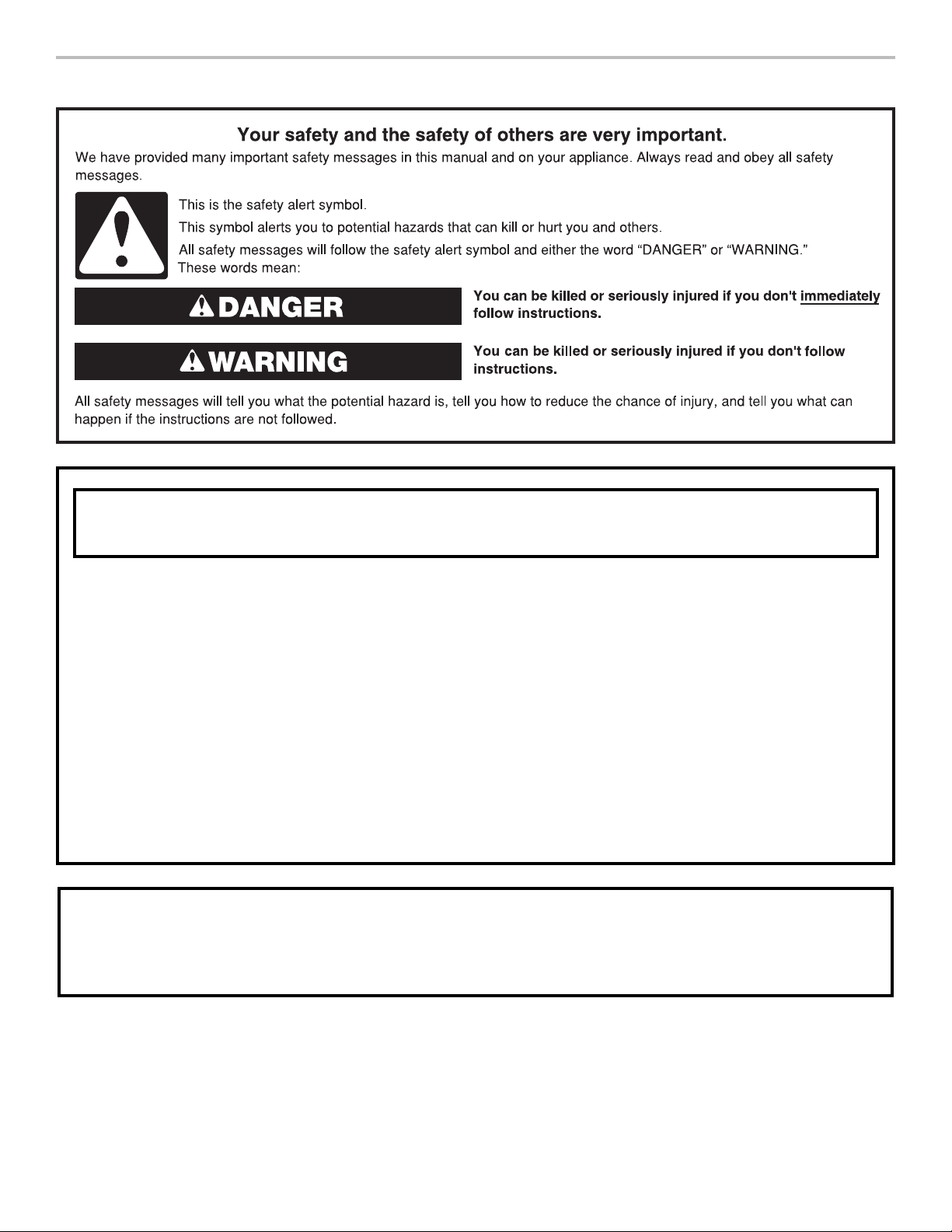
RANGE SAFETY
WARNING: If the information in these instructions is not followed exactly, a fire or
explosion may result causing property damage, personal injury or death.
– Do not store or use gasoline or other flammable vapors and liquids in the vicinity of this
or any other appliance.
– WHAT TO DO IF YOU SMELL GAS:
Do not try to light any appliance.
•
Do not touch any electrical switch.
•
Do not use any phone in your building.
•
Immediately call your gas supplier from a neighbor's phone. Follow the gas supplier's
•
instructions.
If you cannot reach your gas supplier, call the fire department.
•
– Installation and service must be performed by a qualified installer, service agency or
the gas supplier.
WARNING: Gas leaks cannot always be detected by smell.
Gas suppliers recommend that you use a gas detector approved by UL or CSA.
For more information, contact your gas supplier.
If a gas leak is detected, follow the “What to do if you smell gas” instructions.
2
16-Jan-2019 04:15:34 EST | RELEASED
In some European factories the letter "W" of the part code mentioned herein will be automatically
replaced by the number "4000" (e.g. "W12345678" becomes "400012345678")
IMPORTANT: Do not install a ventilation system that blows air downward toward this gas cooking appliance. This type of
ventilation system may cause ignition and combustion problems with this gas cooking appliance resulting in personal injury or
unintended operation.
In the State of Massachusetts, the following installation instructions apply:
■ Installations and repairs must be performed by a qualified or licensed contractor, plumber, or gas fitter qualified or licensed by
the State of Massachusetts.
■ Acceptable Shut-off Devices: Gas Cocks and Ball Valves installed for use shall be listed.
■ A flexible gas connector, when used, must not exceed 4 feet (121.9 cm).
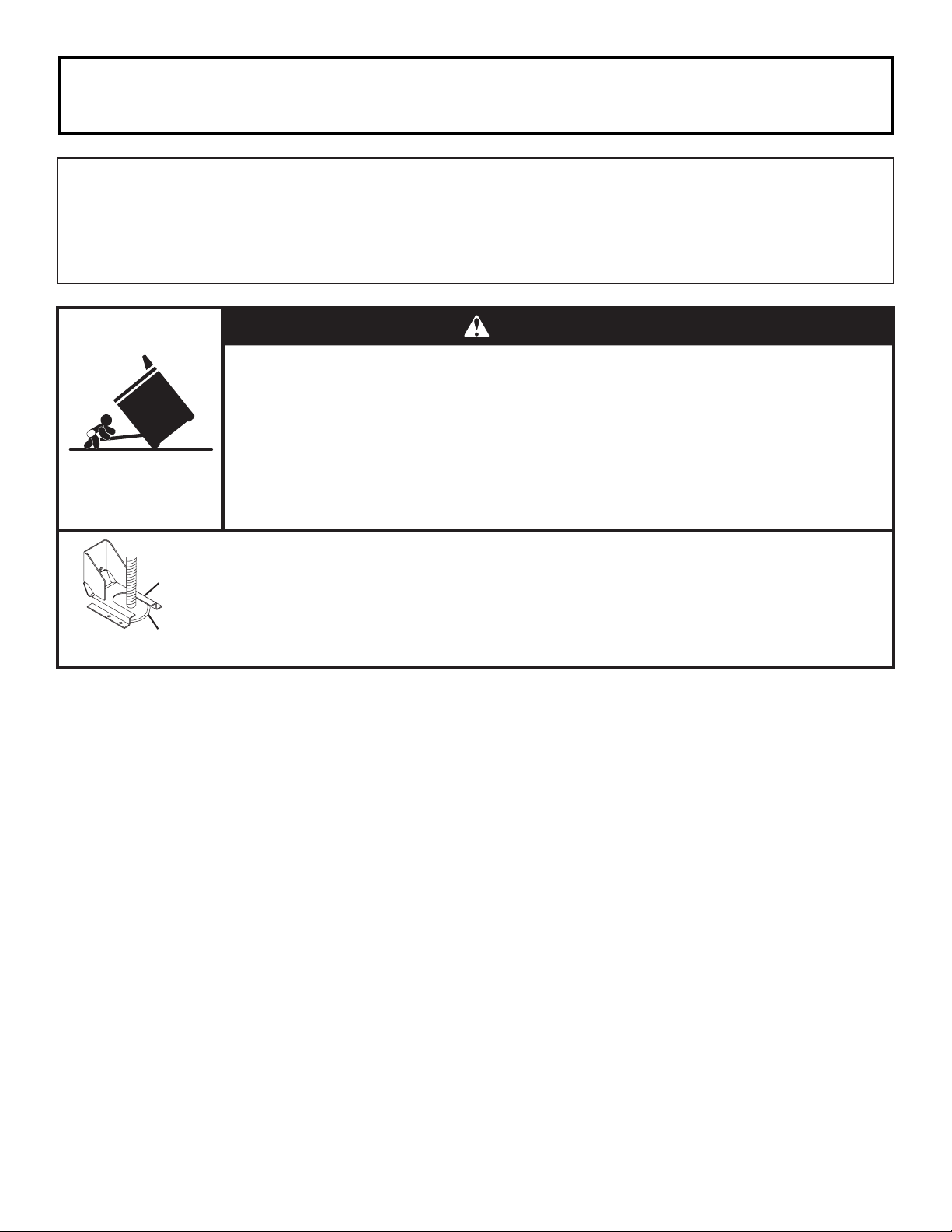
WARNING
Tip Over Hazard
A child or adult can tip the range and be killed.
Install anti-tip bracket to floor or wall per installation instructions.
Slide range back so rear range foot is engaged in the slot of the anti-tip bracket.
Re-engage the anti-tip bracket if the range is moved.
Do not operate range without anti-tip bracket installed and engaged.
Failure to follow these instructions can result in death or serious burns to children and adults.
Anti-Tip
Bracket
Range Foot
To verify the anti-tip bracket is installed and engaged:
• Slide range forward.
• Look for the anti-tip bracket securely attached to floor or wall.
Slide range back so rear range foot is under anti-tip bracket.•
• See installation instructions for details.
16-Jan-2019 04:15:34 EST | RELEASED
In some European factories the letter "W" of the part code mentioned herein will be automatically
replaced by the number "4000" (e.g. "W12345678" becomes "400012345678")
3
INSTALLATION REQUIREMENTS
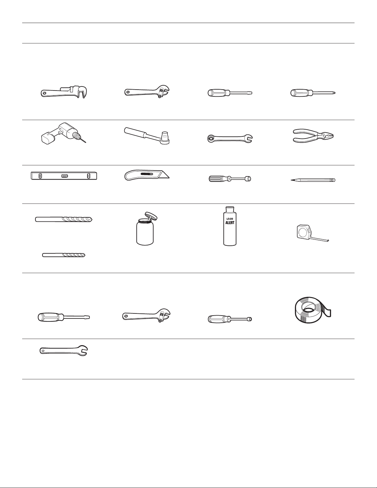
Tools and Parts
Gather the required tools and parts before starting installation. Read and follow the instructions provided with any tools listed here.
Tools Needed
Pipe wrench Adjustable wrench or
5/8"(16mm) wrench
Drill 3/8" (9.5 mm) drive ratchet 15/16" (24 mm)
Level Tubing cutter 1/4" (6.4 mm), 3/8" (9.5 mm),
3/16" (4.8 mm) carbide tip
masonry bit
Pipe-joint compound
resistanttopropanegas
1/8" (3.2 mm) drill bit
1/8" x 41/4" (3mmx100mm)
at-blade screwdriver
combinationwrench
5/16" (7.9 mm) nut drivers
Noncorrosive leak-detection
solution
#2 Phillips screwdriver
Pliers
Marker or pencil
Tape measure
For Propane/Natural Gas Conversions
Large at-blade screwdriver Adjustable wrench T-20 Torx Driver Masking tape
1/2" (1.3 cm) open end
wrench
4
16-Jan-2019 04:15:34 EST | RELEASED
In some European factories the letter "W" of the part code mentioned herein will be automatically
replaced by the number "4000" (e.g. "W12345678" becomes "400012345678")

Parts Supplied
B
Check that all parts are included.
■ Anti-tip bracket kit
A
A. Anti-tip bracket
B. #8-18 x 1" (2.5 cm) Phillips head screws (4)
NOTE: Anti-tip bracket must be securely mounted to
suboor. Thickness of ooring may require longer screws
toanchor bracket to suboor. Longer screws are available
from your local hardware store. See the “Install Anti-Tip
Bracket” section.
■ Burner grates
■ Burner caps
■ Griddle drip tray (on griddle models)
Additional Parts Supplied on Steam-Assist Models (on some
models)
■ Model W10049700 water lter kit
■ 1/4" (6.4 mm) to 1/4" (6.4 mm) water supply union
Water Filtration System Location
Requirements
(on some models)
For best results, do not install the water ltration system outside
or in extreme hot or cold temperatures. Temperature of water
supply to the water ltration system must be between 40°F (4°C)
and 100°F (38°C). Do not install on hot water supply line.
Locate the water ltration system near the cold water supply
pipe under the kitchen sink to lter cold water.
Make sure that the water lter assembly is installed in the upright
position.
It will be necessary to drill a 1/2" (1.3 cm) minimum diameter
hole in the upper-right or left rear corner of the side wall of the
cabinet under the sink to route the water supply tubing through
to the range.
Depending on your installation conguration, more routing holes
may be required.
Coil enough exible codes-approved water supply tubing behind
the range to allow for the connection to the range to be made
behind the range prior to setting the range in place.
Typical Installation Configuration
NOTE: For unique installations, contact a licensed plumber.
In Massachusetts, a licensed plumber is required and the
Commonwealth of Massachusetts Plumbing Code 248-CMR will
be adhered to.
Parts Needed
■ All models must be installed with a backguard if installing
at zero clearance to a combustible back wall surface such
as drywall. See “Cabinet Dimensions” in the “Location
Requirements” section for installation requirements.
Check local codes and consult gas supplier. Check existing gas
supply and electrical supply. See the “Electrical Requirements”
and “Gas Supply Requirements” sections.
It is recommended that all electrical connections be made by
alicensed, qualied electrical installer.
Additional Parts Needed on Steam-Assist Models (on some
models)
■ Tubing staples/retainers
■ 1/4" (6.4 mm) O.D. exible codes-approved water supply
tubing (to make water connection)
■ Water connection device (to connect 1/4" (6.4 mm) O.D.
tubing to water source). Check local codes for type of
connection required.
High Altitude Conversion
To convert the range for elevations above 6,560 ft (2000 m),
order a High Altitude Conversion Kit.
■ Part Number W11238043: High altitude kit
NOTE: Both propane and natural gas conversions are included
in the high altitude kit.
To order, see the “Assistance or Service” section of the Use
andCare Guide.
Cold water
supply
Hot
Cold
Filter
assembly
location
Water Supply Requirements
A cold water supply with water pressure between 30 and 120 psi
(207 and 827 kPa) is required to operate the steam feature. In
Massachusetts, plumbing code 248 CMR 3.00 and 10.00 must
be followed, and a licensed plumber will be used. If you have
questions about your water pressure, call a licensed, qualied
plumber.
Reverse Osmosis Water Supply
IMPORTANT: The pressure of the water supply coming out of
a reverse osmosis system going to the water inlet valve of the
range needs to be between 30 and 120 psi (207 and 827 kPa).
If a reverse osmosis water ltration system is connected to your
cold water supply, the water pressure to the reverse osmosis
system needs to be a minimum of 40 psi (276 kPa).
If the water pressure to the reverse osmosis system is less than
40 psi (276 kPa):
■ Check to see whether the sediment lter in the reverse
osmosis system is blocked. Replace the lter, if necessary.
■ Allow the storage tank on the reverse osmosis system to rell
after heavy usage.
If you have questions about your water pressure, call a licensed,
qualied plumber.
16-Jan-2019 04:15:34 EST | RELEASED
In some European factories the letter "W" of the part code mentioned herein will be automatically
replaced by the number "4000" (e.g. "W12345678" becomes "400012345678")
5
Location Requirements
D
B
IMPORTANT: Observe all governing codes and ordinances.
Donot obstruct ow of combustion and ventilation air.
■ It is the installer’s responsibility to comply with installation
clearances specied on the model/serial/rating plate. The
model/serial/rating plate is located under the console on
theright-hand side.
■ It is recommended that a 600 CFM (17.0 m
range hood beinstalled above the range.
■ Follow the range hood or microwave hood combination
installation instructions for dimensional clearances above the
cooktop surface.
■ Recessed installations must provide complete enclosure
ofthe sides and rear of the range.
■ All openings in the wall or oor where range is to be installed
must be sealed.
■ Do not seal the range to the side cabinets.
■ Cabinet opening dimensions that are shown must be used.
Given dimensions are minimum clearances.
■ The anti-tip bracket must be installed. To install the anti-tip
bracket shipped with the range, see the “Install Anti-Tip
Bracket” section.
■ Grounded electrical supply is required. See the “Electrical
Requirements” section.
■ Proper gas supply connection must be available. See the
“Gas Supply Requirements” section.
■ Contact a qualied oor covering installer to check that the
oor covering can withstand at least 200°F (93°C). Use an
insulated pad or 1/4" (6.4 mm) plywood over carpet and
under range if installing range over carpeting.
IMPORTANT: To avoid damage to your cabinets, check with
your builder or cabinet supplier to make sure that the materials
used will not discolor, delaminate, or sustain other damage. This
oven has been designed in accordance with the requirements
of UL and CSA International and complies with the maximum
allowable wood cabinet temperatures of 194°F (90°C).
Mobile Home - Additional Installation Requirements
The installation of this range must conform to the Manufactured
Home Construction and Safety Standard, Title24CFR,
Part 3280 (formerly the Federal Standard for Mobile Home
Construction and Safety, Title 24, HUD Part 280).When such
standard is not applicable, use the Standard forManufactured
Home Installations, ANSI A225.1/NFPA 501A or local codes.
In Canada, the installation of this range must conform with
thecurrent standards CAN/CSA-A240-latest edition or with
localcodes.
Mobile Home Installations Require:
■ When this range is installed in a mobile home, it must be
secured to the oor during transit. Any method of securing
the range is adequate as long as it conforms to the
standards listed above.
3
/hr) or larger
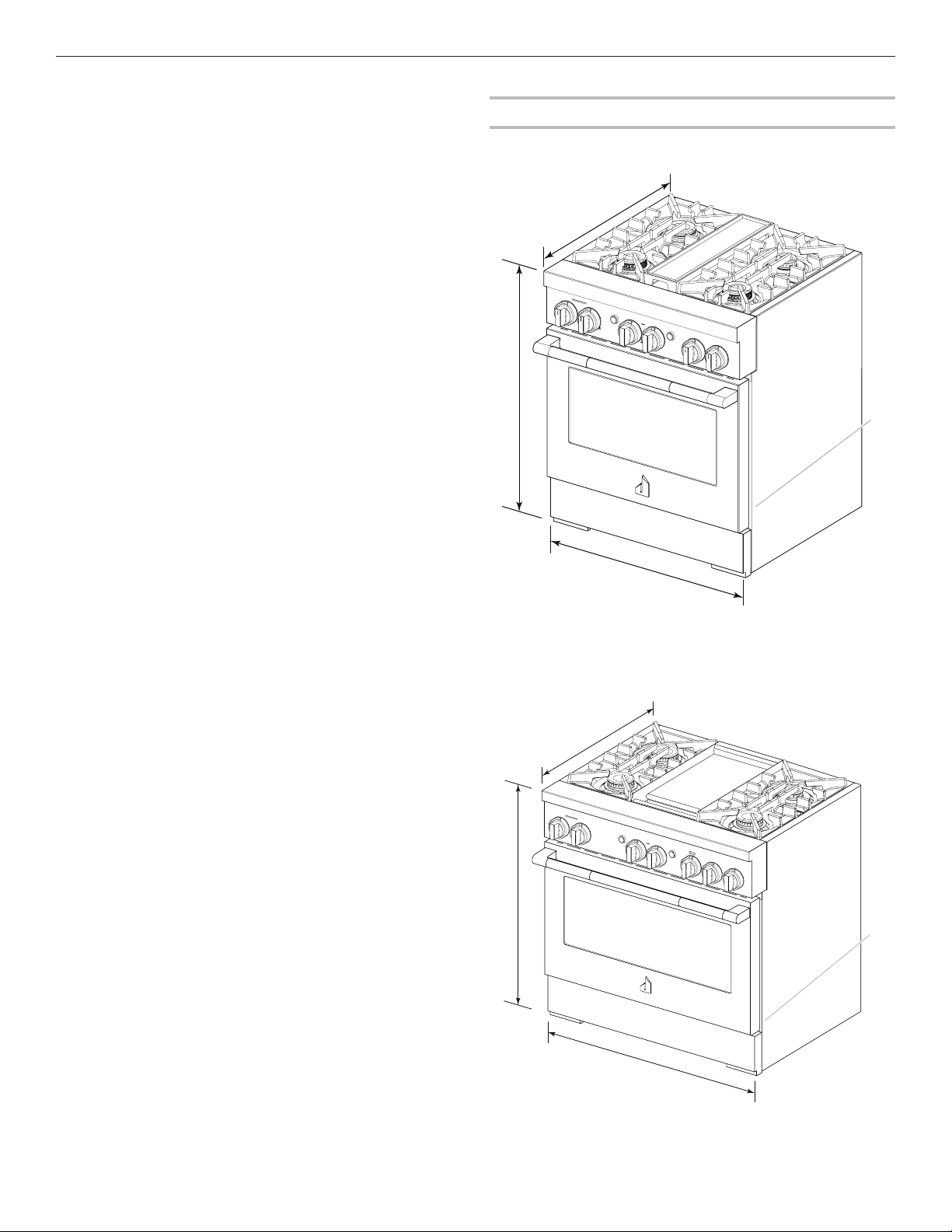
Product Dimensions
NOTE: Cooktop features may differ.
30" (76.2 cm) models
A
B
D
C
A. 273/4" (70.5 cm) depth with control panel (See NOTE.)
B. 353/4" (90.8 cm) range height when sitting on the wheels
C. 297/8 " (75.7 cm) width
D. Model/serial/rating plate location/SAID label
(located on front side panel)
36" (91.4 cm) models
A
6
16-Jan-2019 04:15:34 EST | RELEASED
A. 271⁄8" (68.9 cm) depth with control panel (See NOTE.)
B. 353⁄4" (90.8 cm) range height when sitting on the wheels
C. 36" (91.4 cm) width
D. Model/serial/rating plate location/SAID label
(located on front side panel)
In some European factories the letter "W" of the part code mentioned herein will be automatically
replaced by the number "4000" (e.g. "W12345678" becomes "400012345678")
C
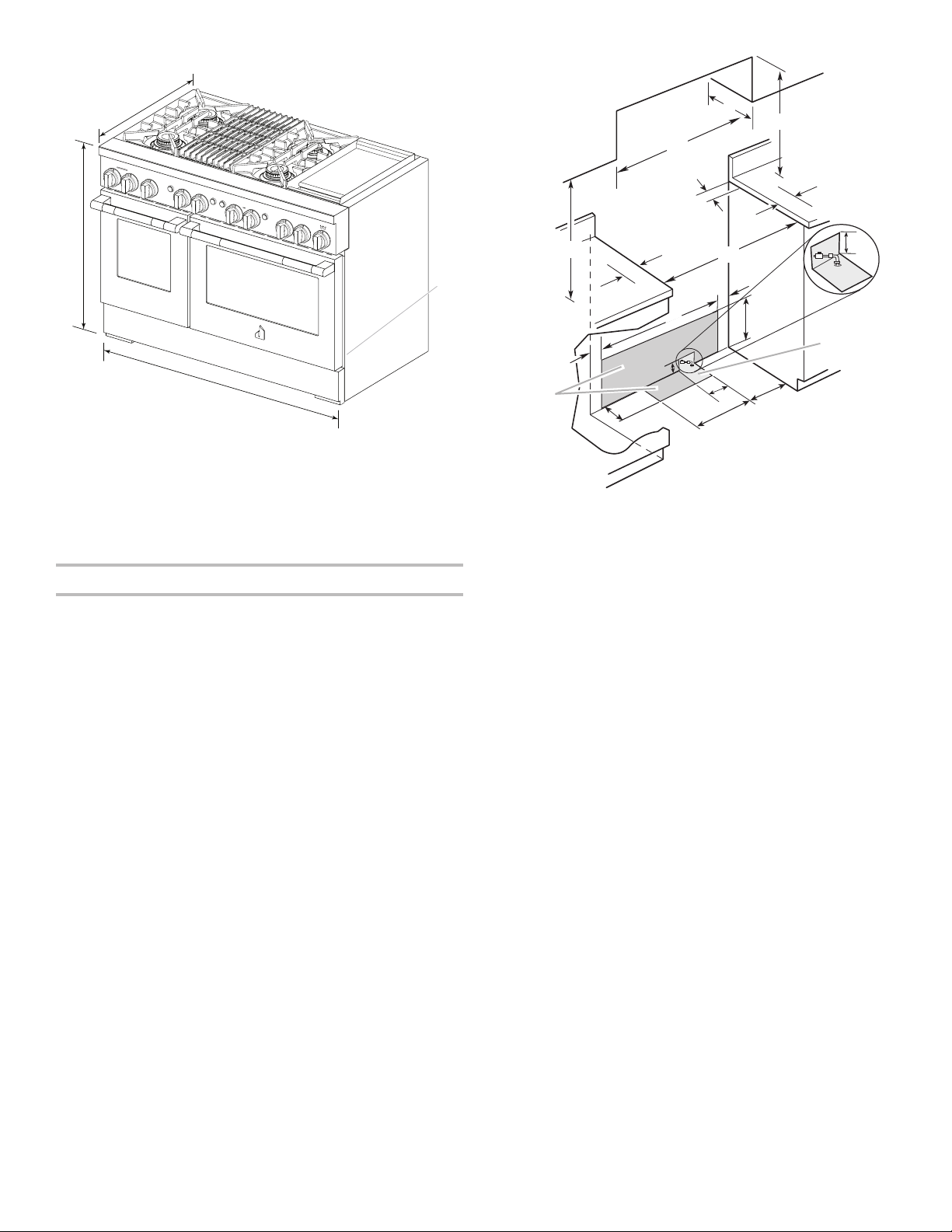
48" (121.9 cm) models
D
Electrical
installation
area*
installation
A
B
C
A. 271⁄8" (68.9 cm) depth with control panel (See NOTE.)
B. 353⁄4" (90.8 cm) range height when sitting on the wheels
C. 48" (121.9 cm) width
D. Model/serial/rating plate location/SAID label
(located on front side panel)
NOTE: When installed in a 24" (61.0 cm) base cabinet with 25"
(63.5 cm) countertop; front of oven door protrudes 17/8" (4.8 cm)
beyond 24" (61.0 cm) base cabinet.
Cabinet Requirements
Cabinet opening dimensions shown are for 25" (64.0 cm)
countertop depth, 24" (61.0 cm) base cabinet depth, and
36"(91.4 cm) countertop height. Dimensions must be met
inorder to ensure a ush t to back wall.
IMPORTANT: If installing a range hood or microwave hood
combination above the cooking surface, follow the range hood
or microwave hood combination installation instructions for
dimensional clearances above the cooking surface.
C
**
D
B
O***
A
E
F
J
F
I
H
I
G
Gas
area
J
L
K
N
M
A. 18" (45.7 cm) upper cabinet to countertop
B. 30" (76.2 cm) model: 30" (76.2 cm) min. upper cabinet width
36" (91.4 cm) model: 36" (91.4 cm) min. upper cabinet width
48" (121.9 cm) model: 48" (121.9 cm) min. upper cabinet width
C. 13" (33 cm) max. upper cabinet depth
D. For minimum clearance to top of range.**
E. 30" (76.2 cm) on 30" (76.2 cm) models
36" (91.4 cm) on 36" (91.4 cm) models
48" (121.9 cm) on 48" (121.9 cm) models
F. 12" (30.4 cm) min. clearance from both sides of range to side
wall or other combustible material
G. 15" (38.1 cm)
H. 22" (55.9 cm) on 30" (76.2 cm) models
28" (71.1 cm) on 36" (91.4 cm) models
40" (101.6 cm) on 48" (121.9 cm) models
I. 4" (10.1 cm)
J. 3" (7.6 cm)
K. 5" (12.7 cm)
L. 6" (15.2 cm) on 30" (76.2 cm) models
14" (35.5 cm) on 36" (91.4 cm) models
24" (61.0 cm) on 48" (121.9 cm) models
M. 101/2" (26.7 cm)
N. 6" (15.2 cm)
O. 6" (15.2 cm)***
** Minimum Clearances
30" (76.2 cm) models: 42" (106.7 cm) minimum clearance
between the top of the cooking platform and the bottom of a
combustible surface
36" (91.4 cm) models: 58" (147.3 cm) minimum clearance
between the top of the cooking platform and the bottom of a
combustible surface
48" (121.9 cm) models: 58" (147.3 cm) minimum clearance
between the top of the cooking platform and the bottom of a
combustible surface
*** If the surface of the back wall is constructed of a combustible
material and a backguard is not installed, a 6" (15.2 cm)
minimum clearance is required for all models.
16-Jan-2019 04:15:34 EST | RELEASED
In some European factories the letter "W" of the part code mentioned herein will be automatically
replaced by the number "4000" (e.g. "W12345678" becomes "400012345678")
7
Electrical Requirements:
U.S.A. Only
If codes permit and a separate ground wire is used, it is
recommended that a qualied electrical installer determine
thatthe ground path and wire gauge are in accordance with
local codes.
If codes permit and a separate ground wire is used, it is
recommended that a qualied electrician determine that
theground path is adequate.
Do not use an extension cord.
Be sure that the electrical connection and wire size are adequate
and in conformance with the National Electrical Code, ANSI/
NFPA 70 — latest edition — and all local codes and ordinances.
A copy of the above code standards can be obtained from:
National Fire Protection Association
1 Batterymarch Park
Quincy, MA 02169-7471
WARNING: Improper connection of the equipment-grounding
conductor can result in a risk of electric shock. Check with a
qualied electrician or service technician if you are in doubt as
towhether the appliance is properly grounded. Do not modify
the power supply cord plug. If it will not t the outlet, have a
proper outlet installed by a qualied electrician.
Electrical Connection
To properly install your range, you must determine the type of
electrical connection you will be using and follow the instructions
provided for it here.
■ Range must be connected to the proper electrical voltage
and frequency as specied on the model/serial/rating plate.
The model/serial/rating plate is located under the console
on the right-hand side. Refer to the illustrations in “Product
Dimensions” in the “Location Requirements” section.
■ This range is manufactured with a 4-wire power supply cord.
■ A circuit breaker is recommended.
■ Wire sizes and connections must conform with the rating
ofthe range.
NOTE: If your home does not have a 4-wire system, consult
your local qualied electrician.
Electrical Requirements:
Canada Only
WARNING
A copy of the above code standards can be obtained from:
Canadian Standards Association
178 Rexdale Blvd.
Toronto, ON M9W 1R3 CANADA
■ Check with a qualied electrical installer if you are not sure
the range is properly grounded.
■ When a 4-wire, single-phase 250 V, 60 Hz, AC-only electrical
supply is available, a 40 A minimum circuit protection is
required on 30" (76.2 cm) and 36" (91.4 cm) ranges and a
50 A minimum circuit protection is required on 48"
(121.9 cm) ranges, fused on both sides of the line.
■ A time-delay fuse or circuit breaker is recommended.
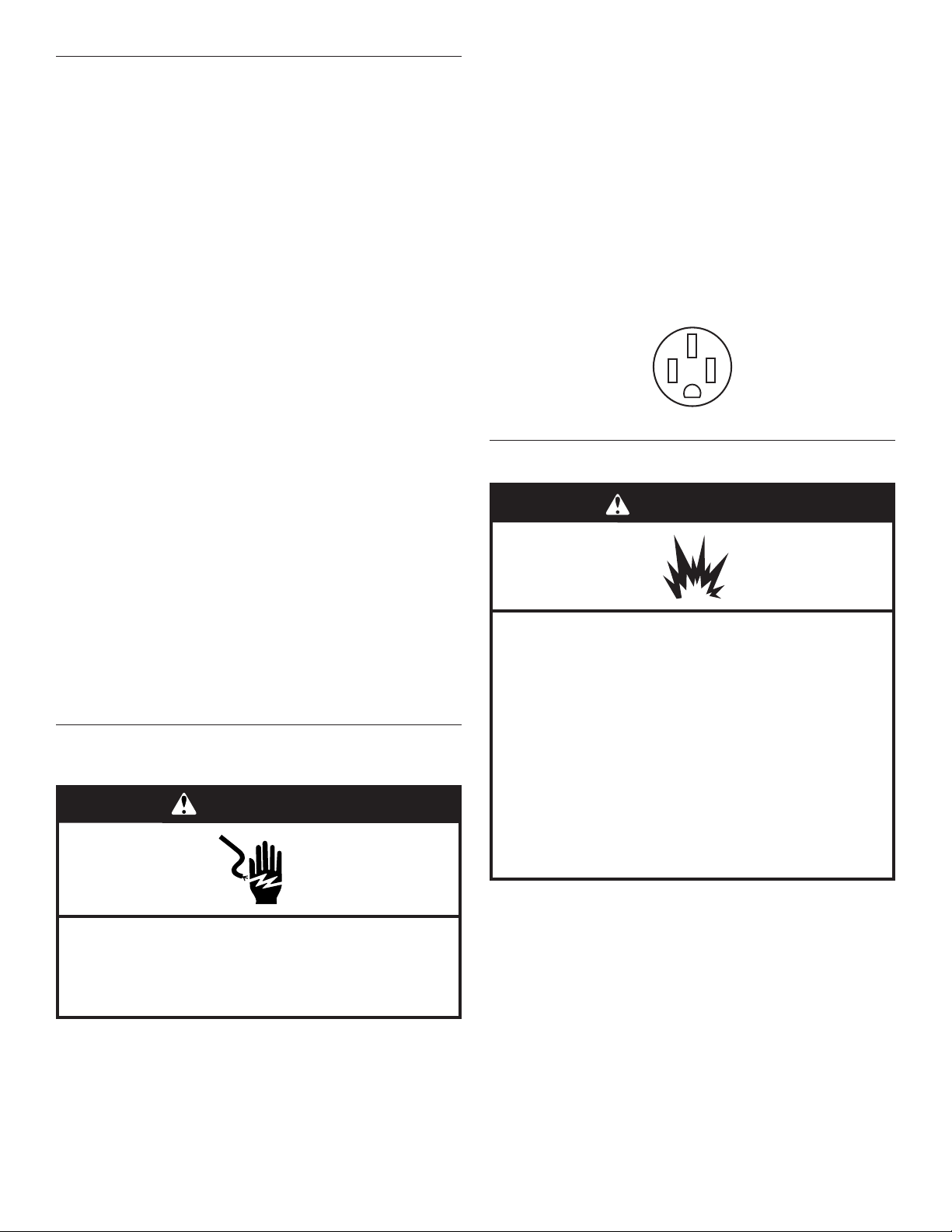
■ This range is equipped with a CSA International Certied
Power Cord intended to be plugged into a standard 14-50R
wall receptacle. Be sure the wall receptacle is within reach of
range’s nal location.
■ Do not use an extension cord.
Gas Supply Requirements
WARNING
Explosion Hazard
Use a new CSA International approved gas supply line.
Install a shut-off valve.
Securely tighten all gas connections.
If connected to propane, have a qualified person make
sure gas pressure does not exceed 14" (36 cm) water
column.
Examples of a qualified person include:
licensed heating personnel,
authorized gas company personnel, and
authorized service personnel.
Failure to do so can result in death, explosion, or fire.
Electrical Shock Hazard
Electrically ground range.
Failure to do so can result in death, fire, or
electrical shock.
If codes permit and a separate ground wire is used, it is
recommended that a qualied electrical installer determine
thatthe ground path and wire gauge are in accordance with
local codes.
Be sure that the electrical connection and wire size are adequate
and in conformance with the CSA Standard C22.1, Canadian
Electrical Code, Part 1 — latest edition — and all local codes
andordinances.
8
In some European factories the letter "W" of the part code mentioned herein will be automatically
16-Jan-2019 04:15:34 EST | RELEASED
Observe all governing codes and ordinances.
IMPORTANT: This installation must conform with all local codes
and ordinances. In the absence of local codes, installation must
conform with American National Standard, National Fuel Gas
Code ANSI Z223.1 — latest edition — or CAN/CGA B149 —
latest edition.
IMPORTANT: Range must be connected to a regulated
gassupply.
IMPORTANT: Leak testing of the range must be conducted
according to the manufacturer’s instructions.
replaced by the number "4000" (e.g. "W12345678" becomes "400012345678")
 Loading...