

Jenn-Air JGRP430HL, JGRP430HM, JGRP436HL, JGRP436HM, JGRP536HL Installation Instructions
...Page 1
INSTALLATION INSTRUCTIONS
IMPORTANT:
Installer:
Homeo
IMPOR
Installateur
Pr
.
CommerCial-Style GaS CooktopS
30" (76.2 Cm), 36" (91.4 Cm) and 48" (121.9 Cm)
For residential use only
INSTRUCTIONS D’INSTALLATION
table de CuiSSon au Gaz de Style CommerCial de
30 po (76,2 Cm), 36 po (91,4 Cm) et 48 po (121,9 Cm)
Pour utilisation résidentielle uniquement
Table of Contents/Table des matières
COOKTOP SAFETY ........................................................................2
INSTALLATION REQUIREMENTS .................................................3
Tools and Parts .............................................................................3
Location Requirements ................................................................4
Electrical Requirements ...............................................................9
Gas Supply Requirements ...........................................................9
INSTALLATION INSTRUCTIONS .................................................10
Install Cooktop ...........................................................................10
Make Gas Connection ...............................................................11
Install Griddle Tray ......................................................................12
Complete Installation .................................................................12
GAS CONVERSIONS ....................................................................13
Propane Gas Conversion ...........................................................13
Natural Gas Conversion .............................................................16
SÉCURITÉ DE LA TABLE DE CUISSON .....................................19
EXIGENCES D’INSTALLATION ...................................................20
Outils et pièces ...........................................................................20
Exigences d’emplacement .........................................................21
Spécications électriques ..........................................................26
Spécications de l’alimentation en gaz .....................................26
INSTRUCTIONS D’INSTALLATION .............................................28
Installation de la table de cuisson ..............................................28
Effectuer le raccordement au gaz ..............................................28
Installer le plateau d’égouttement .............................................30
Terminer l’installation ..................................................................30
CONVERSIONS POUR CHANGEMENT DE GAZ ......................31
Conversion pour l’alimentation aupropane ..............................31
Conversion pour l’alimentation augaz naturel ..........................34
Leave installation instructions with the homeowner.
wner: Keep installation instructions for future reference.
W11110989C
16-Jan-2019 04:15:35 EST | RELEASED
TANT :
: Remettre les instructions d'installation au propriétaire.
opriétaire : Conserver les instructions d'installation pour référence ultérieure
www.jennair.com (U.S.A.) www.jennair.ca (Canada)
In some European factories the letter "W" of the part code mentioned herein will be automatically
replaced by the number "4000" (e.g. "W12345678" becomes "400012345678")
Page 2
COOKTOP SAFETY
WARNING: If the information in these instructions is not followed exactly, a fire or
explosion may result causing property damage, personal injury or death.
– Do not store or use gasoline or other flammable vapors and liquids in the vicinity of this
or any other appliance.
– WHAT TO DO IF YOU SMELL GAS:
Do not try to light any appliance.
•
Do not touch any electrical switch.
•
Do not use any phone in your building.
•
Immediately call your gas supplier from a neighbor's phone. Follow the gas supplier's
•
instructions.
If you cannot reach your gas supplier, call the fire department.
•
Installation and service must be performed by a qualified installer, service agency or
–
the gas supplier.
WARNING: Gas leaks cannot always be detected by smell.
Gas suppliers recommend that you use a gas detector approved by UL or CSA.
For more information, contact your gas supplier.
If a gas leak is detected, follow the “What to do if you smell gas” instructions.
2
16-Jan-2019 04:15:35 EST | RELEASED
In some European factories the letter "W" of the part code mentioned herein will be automatically
replaced by the number "4000" (e.g. "W12345678" becomes "400012345678")
Page 3
IMPORTANT: Do not install a ventilation system that blows air downward toward this gas cooking appliance. This type of
ventilation system may cause ignition and combustion problems with this gas cooking appliance resulting in personal injury or
unintended operation.
In the State of Massachusetts, the following installation instructions apply:
■ Installations and repairs must be performed by a qualified or licensed contractor, plumber, or gas fitter qualified or licensed by
the State of Massachusetts.
■ Acceptable Shut-off Devices: Gas Cocks and Ball Valves installed for use shall be listed.
■ A flexible gas connector, when used, must not exceed 4 feet (121.9 cm).
INSTALLATION REQUIREMENTS
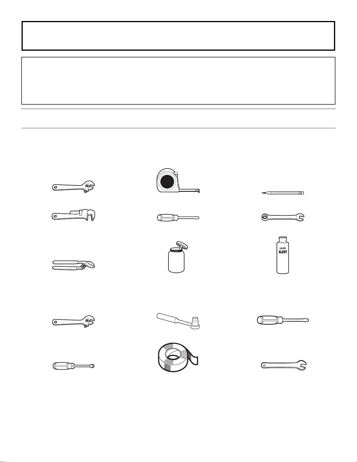
Tools and Parts
Gather the required tools and parts before starting installation. Read and follow the instructions provided with any tools listed here.
Tools Needed
Adjustable wrench Tape measure Marker or pencil
Pipe wrench Flat-blade screwdriver 15/16" (24 mm) combination wrench
Wrench or channel lock pliers Pipe-joint compound
resistant to Propane gas
For Propane/Natural Gas Conversions
Adjustable wrench Drive ratchet Large flat-blade screwdriver
Noncorrosive leak-detection solution
T-20 Torx Driver Masking tape 1/2" (1.3 cm) open end wrench
16-Jan-2019 04:15:35 EST | RELEASED
In some European factories the letter "W" of the part code mentioned herein will be automatically
replaced by the number "4000" (e.g. "W12345678" becomes "400012345678")
3
Page 4

Parts Supplied
Check that all parts are included.
■ Gas pressure regulator
■ Burner grates
■ Burner caps
■ Griddle drip tray (on griddle models)
■ Foam tape
Parts Needed
All models must be installed with a backsplash if installing at
zero clearance to a combustible back wall. See the “Cabinet
Dimensions” section in the “LocationRequirements” section for
installation requirements.
To order, see the “Assistance or Service” section of the Use
andCare Guide.
Check local codes and consult gas supplier. Check existing gas
supply and electrical supply. See the “Electrical Requirements”
and “Gas Supply Requirements” sections.
High Altitude Conversion
To convert the cooktop for elevations above 6,560 ft (2000 m),
order a High Altitude Conversion Kit.
■ Part Number W11238043: High altitude kit
NOTE: Both propane and natural gas conversions are included
in the high altitude kit.
To order, see the “Assistance or Service” section of the Use and
Care Guide.
NOTE: The cooktop is manufactured for use with Natural gas. To
convert to Propane gas, see the “Gas Conversions” section.
Location Requirements
IMPORTANT: Observe all governing codes and ordinances.
Donot obstruct ow of combustion and ventilation air.
■ It is the installer’s responsibility to comply with installation
clearances specied on the model/serial/rating plate. The
model/serial/rating plate is located on the underside of the
cooktop burner base.
■ It is recommended that a 600 CFM (17.0 m
hood beinstalled above the cooktop.
■ Follow the range hood or microwave hood combination
installation instructions for dimensional clearances above the
cooktop surface.
■ The cooktop should be installed in a location away from
strong draft areas, such as windows, doors, and strong
heating vents or fans.
■ All openings in the wall or oor where cooktop is to be
installed must be sealed.
■ Cabinet opening dimensions that are shown must be used.
Given dimensions are minimum clearances.
■ Grounded electrical supply is required. See the “Electrical
Requirements” section.
■ Proper gas supply connection must be available. See the
“GasSupply Requirements” section.
■ The cooktop is designed to be supported by a solid oor in
the opening, not hung from the countertop by its side or rear
anges.
■ The gas and electric supply should be located as shown
inthe “Gas and Electric Connection Locations” section
sothat they are accessible without requiring removal of
thecooktop.
■ Provide cutout in left rear corner of cutout enclosure as
shown to provide clearance for gas inlet, power supply cord,
and to allow the rating label to be visible.
IMPORTANT: To avoid damage to your cabinets, check with
your builder or cabinet supplier to make sure that the materials
used will not discolor, delaminate, or sustain other damage.
3
/hr) or larger vent
Mobile Home - Additional Installation Requirements
The installation of this cooktop must conform to the
Manufactured Home Construction and Safety Standard,
Title24CFR, Part 3280 (formerly the Federal Standard for
Mobile Home Construction and Safety, Title 24, HUD Part
280).When such standard is not applicable, use the Standard
forManufactured Home Installations, ANSI A225.1/NFPA 501A
or local codes.
In Canada, the installation of this cooktop must conform with
thecurrent standards CAN/CSA-A240-latest edition or with
localcodes.
4
16-Jan-2019 04:15:35 EST | RELEASED
In some European factories the letter "W" of the part code mentioned herein will be automatically
replaced by the number "4000" (e.g. "W12345678" becomes "400012345678")
Page 5
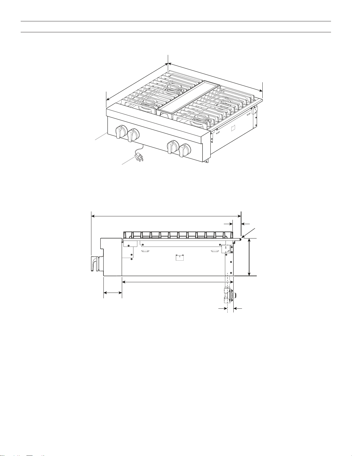
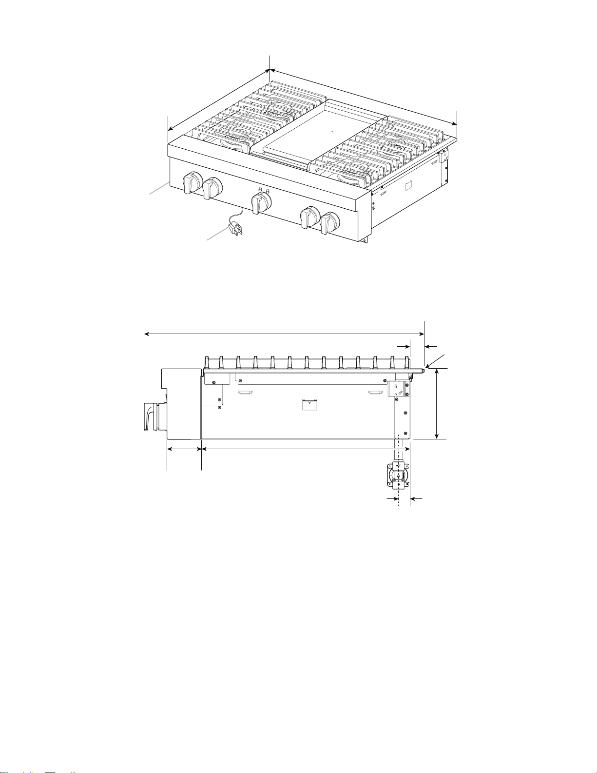
Product Dimensions
C
D
A
NOTE: Cooktop features may differ.
30" (76.2 cm) models
Side View of Cooktop
A. 271/8" (68.9 cm)
B. 297/8" (75.9 cm)
A
B
C. 3 prong grounding-type power supply cord
D. Model/serial/rating plate (located on the
underside of the cooktop burner base)
B
C
G
A. 273/8" (69.5 cm)
B. 11/4" (3.2 cm)
C. Island trim or optional backguard
D. 77/16" (18.8 cm)
D
F
E
E. Gas inlet is located 17/8" (4.8 cm) from the
back of the cooktop burner base and 47/8"
(12.4 cm) in from left-hand side of the
cooktop burner base.
F. 22" (55.9 cm)
G. 35/16" (8.4 cm)
16-Jan-2019 04:15:35 EST | RELEASED
In some European factories the letter "W" of the part code mentioned herein will be automatically
replaced by the number "4000" (e.g. "W12345678" becomes "400012345678")
5
Page 6
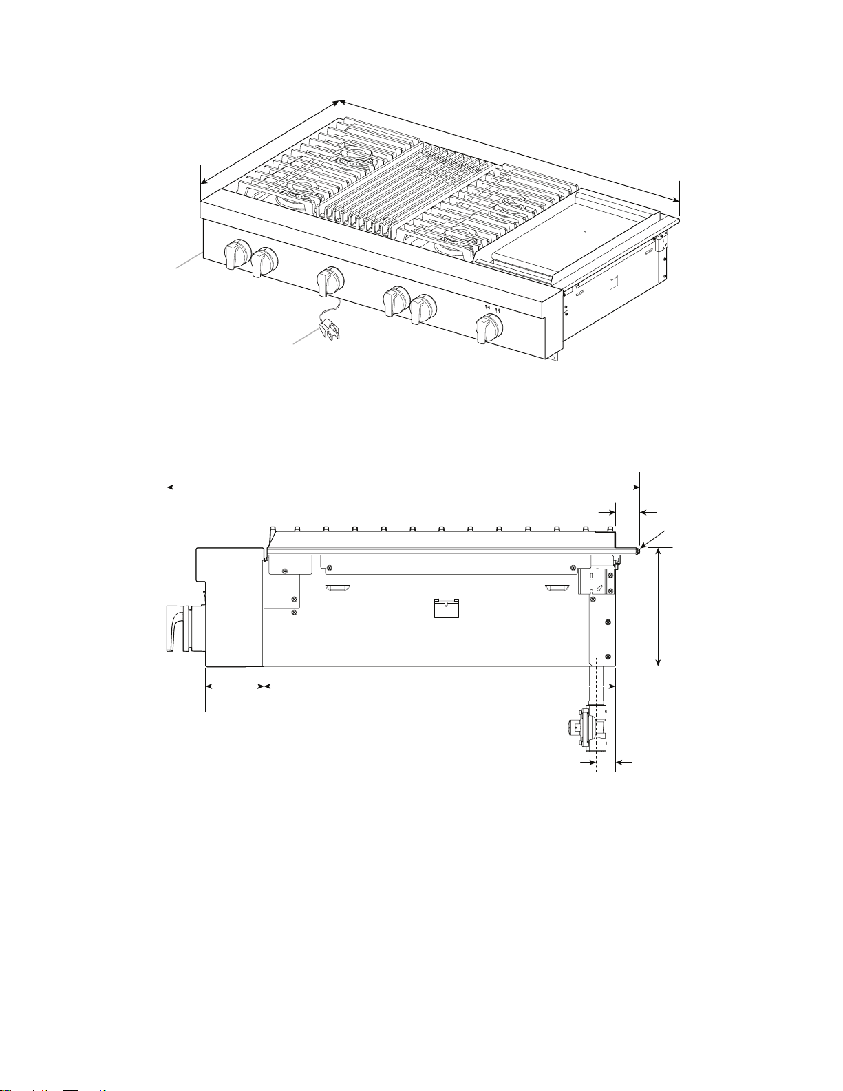
36" (91.4 cm) models
C
D
Side View of Cooktop
A. 271/8" (68.9 cm)
B. 353/4" (90.8 cm)
A
C. 3 prong grounding-type power supply cord
D. Model/serial/rating plate (located on the
underside of the cooktop burner base)
B
A
B
C
G
A. 273/8" (69.5 cm)
B. 11/4" (3.2 cm)
C. Island trim or optional backguard
D. 77/16" (18.8 cm)
D
F
E
E. Gas inlet is located 17/8" (4.8 cm) from
the back of the cooktop burner base and
47/8" (12.4 cm) in from left-hand side of the
cooktop burner base.
F. 22" (55.9 cm)
G. 35/16" (8.4 cm)
6
16-Jan-2019 04:15:35 EST | RELEASED
In some European factories the letter "W" of the part code mentioned herein will be automatically
replaced by the number "4000" (e.g. "W12345678" becomes "400012345678")
Page 7
48" (121.9 cm) models
D
Side View of Cooktop
A
A. 271/8" (68.9 cm)
B. 477/8" (121.6 cm)
B
C
C. 3 prong grounding-type power supply cord
D. Model/serial/rating plate (located on the
underside of the cooktop burner base)
A
B
C
D
G
F
E
A. 273/8" (69.5 cm)
B. 11/4" (3.2 cm)
C. Island trim or optional backguard
D. 77/16" (18.8 cm)
E. Gas inlet is located 17/8" (4.8 cm) from
the back of the cooktop burner base and
47/8" (12.4 cm) in from left-hand side of the
cooktop burner base.
F. 22" (55.9 cm)
G. 35/16" (8.4 cm)
16-Jan-2019 04:15:35 EST | RELEASED
In some European factories the letter "W" of the part code mentioned herein will be automatically
replaced by the number "4000" (e.g. "W12345678" becomes "400012345678")
7
Page 8
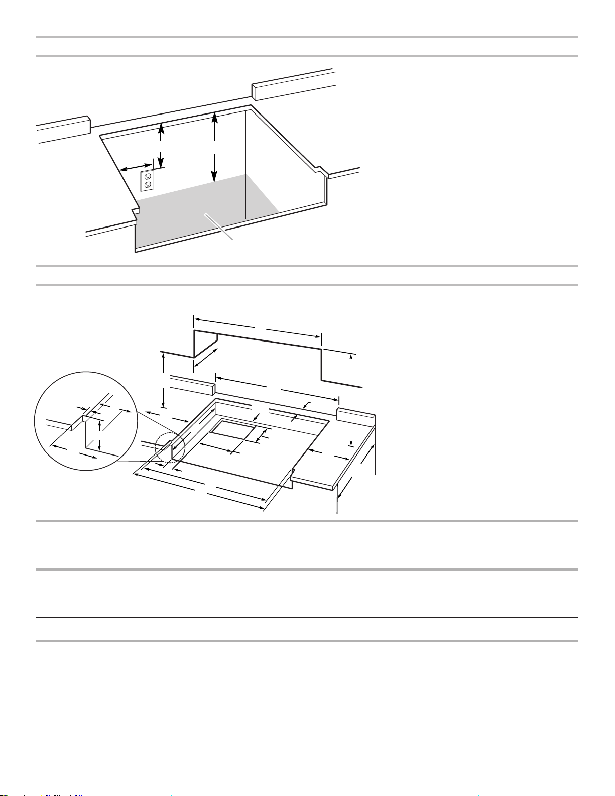
Gas and Electric Connection Locations
A. Grounded 3 prong outlet should be located on
left-hand side of the cutout 16" (40.6 cm) max.
from enclosure sidewall
B. 10" (25.4 cm) min. clearance from countertop to
top of the outlet
C. 14" (35.6 cm) countertop to the gas supply line
D. Gas supply line should be located in this area on
rear or side walls or the supply line can come up
B
C
A
through the floor.
NOTE: Solid side and bottom of cutout enclosure
not shown.
D
Cabinet Requirements
IMPORTANT: If installing a range hood or microwave hood combination above the cooking surface, follow the range hood or
microwave hood combination installation instructions for dimensional clearances above the cooktop surface.
C
P
F
C
O
D
G
A*
B min.**
L
N
E
J
H
I
K
L
M
D
E
A. See chart.
B. See chart.
C. See chart.
D. See chart.
E. See chart.
F. 18" (45.7 cm) min. clearance upper cabinet
to countertop
G. 3/4" (19 mm) back of cabinet cutout to gas
opening cutout
H. 67/8" (16.1 cm) gas opening cutout depth
I. 121/2" (31.7 cm) gas opening cutout width
J. 221/4" (56.5 cm) cabinet cutout depth
K. 2" (5.1 cm) cabinet side to gas cutout
L. 6" (15.2 cm) min. distance on both sides of the
cooktop to the side wall or other combustible
material above cooking surface
M. 24" (61.0 cm) cabinet depth
N. 71/4" (18.4 cm) cabinet depth to countertop
O. Notch to be equal on both sides
P. 13" (33.0 cm) upper cabinet depth
Size A*
Cooktop Cutout
to Back Wall
B**
Cooktop to
Cabinet
C
Optional Backguard
and Upper Cabinet
D
Cabinet and
Countertop
E
Countertop Only
Opening
30" (76.2 cm) 13/4" (4.4 cm)* 42" (106.7 cm) 30" (76.2 cm) 291/4" (74.3 cm) 297/8"(75.9cm) for
zeroclearance
36" (91.4 cm) 13/4" (4.4 cm)* 58" (147.3 cm) 36" (91.4 cm) 351/4" (89.5 cm) 353/4"(90.8cm) for
zeroclearance
48" (121.9 cm) 13/4" (4.4 cm)* 58" (147.3 cm) 48" (121.9 cm) 471/4" (120.0 cm) 477/8"(121.6cm) for
zeroclearance
* NOTE: If back wall is constructed of a combustible material and a backguard is not installed, a minimum clearance of
dimensionA+6" (15.2 cm) is required for all models.
If installing a range hood above the cooktop, follow the range hood instructions for dimensional clearances above the
cooktopsurface.
NOTE: Due to manufacturing factory tolerances, these are nominal dimensions. You may need to readjust to meet your clearance.
8
16-Jan-2019 04:15:35 EST | RELEASED
In some European factories the letter "W" of the part code mentioned herein will be automatically
replaced by the number "4000" (e.g. "W12345678" becomes "400012345678")
Page 9
Electrical Requirements
IMPORTANT: The cooktop must be electrically grounded in
accordance with local codes and ordinances or, in the absence
of local codes, with the National Electrical Code, ANSI/NFPA 70
or Canadian Electrical Code, CSA C22.1.
This cooktop is equipped with an electronic ignition system
that will not operate if plugged into an outlet that is not
properlypolarized.
If codes permit and a separate ground wire is used, it is
recommended that a qualied electrical installer determine
thatthe ground path is adequate.
A copy of the above code standards can be obtained from:
National Fire Protection Association
1 Batterymarch Park
Quincy, MA 02169-7471
CSA International
8501 East Pleasant Valley Road
Cleveland, Ohio 44131-5575
■ A 120 V, 60 Hz, AC-only, 15 A, fused electrical circuit
is required. A time-delay fuse or circuit breaker is also
recommended. It is recommended that a separate circuit
serving only this cooktop be provided.
■ Electronic ignition systems operate within wide voltage limits,
but proper grounding and polarity are necessary. Check that
the outlet provides 120 V power and is correctly grounded.
■ The wiring diagrams are provided with this cooktop. The
wiring diagrams are located inside the control console.
Gas Supply Requirements
WARNING
Explosion Hazard
Use a new CSA International approved gas supply line.
Install a shut-off valve.
Securely tighten all gas connections.
If connected to propane, have a qualified person make
sure gas pressure does not exceed 14" (36 cm) water
column.
Examples of a qualified person include:
licensed heating personnel,
authorized gas company personnel, and
authorized service personnel.
Failure to do so can result in death, explosion, or fire.
Observe all governing codes and ordinances.
IMPORTANT: This installation must conform with all local codes
and ordinances. In the absence of local codes, installation must
conform with American National Standard, National Fuel Gas
Code ANSI Z223.1 - latest edition or CAN/CGA B149 - latest
edition.
IMPORTANT: Leak testing of the cooktop must be conducted
according to the manufacturer’s instructions.
Type of Gas
Natural Gas:
This cooktop is factory-set for use with Natural gas. To convert
to Propane gas, see the “Gas Conversions” section. The
model/serial/rating plate located on the left underside of the
cooktop burner base has information on the types of gas that
can be used. If the types of gas listed do not include thetype of
gas available, check with the local gas supplier.
Propane Gas conversion:
Conversion must be done by a qualied service technician.
No attempt shall be made to convert the cooktop from the gas
specied on the model/serial/rating plate for use with a different
gas without consulting the serving gas supplier. To convert to
Propane gas, use the Propane gas conversion kit provided with
the cooktop and see the “Gas Conversions” section.
16-Jan-2019 04:15:35 EST | RELEASED
In some European factories the letter "W" of the part code mentioned herein will be automatically
replaced by the number "4000" (e.g. "W12345678" becomes "400012345678")
9
Page 10
Gas Supply Line
A
C
A
C
Gas Pressure Regulator
■ Provide a gas supply line of 3/4" (1.9 cm) rigid pipe to the
cooktop location. A smaller size pipe on longer runs may
result in insufcient gas supply. With Propane gas, piping or
tubing size can be 1/2" (1.3 cm) minimum. Usually, Propane
gas suppliers determine the size and materials used in the
system.
NOTE: Pipe-joint compounds that resist the action of
Propane gas must be used. Do not use TEFLON®† tape.
■ Flexible metal appliance connector:
■ If local codes permit, a new CSA design-certied, 4-5ft
(122-152 cm) long, 5/8" (1.6 cm) or 3/4" (1.9 cm) I.D.,
exible metal appliance connector may be used for
connecting the cooktop to the gas supply line.
■ A 1/2" (1.3 cm) male pipe thread is needed for
connection to the female pipe threads of the inlet to the
appliance pressure regulator.
■ Do not kink or damage the exible metal tubing when
moving the cooktop.
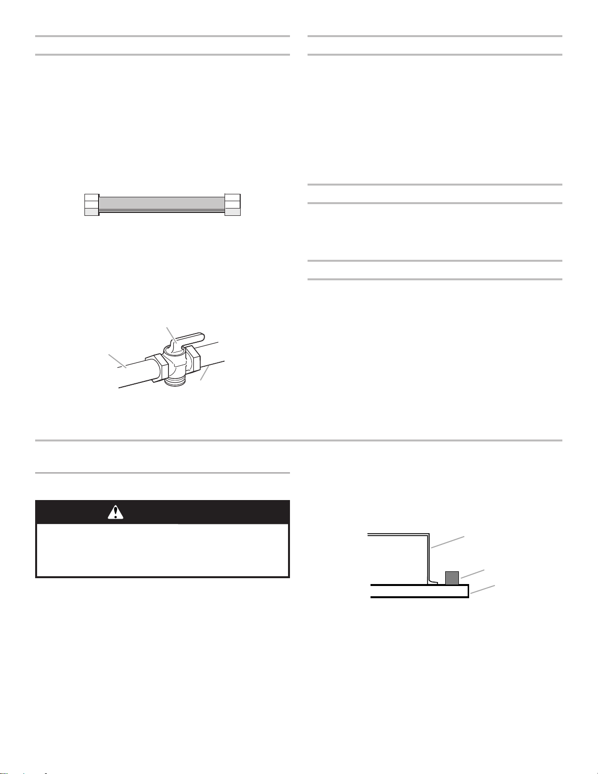
■ Must include a shut-off valve:
Install a manual gas line shut-off valve in an easily accessible
location. Do not block access to shut-off valve. The valve is
for turning on or shutting off gas to the cooktop.
B
A. Gas supply line
B. Shut-off valve “open” position
C. To cooktop
The gas pressure regulator supplied with this cooktop must
beused. The inlet pressure to the regulator should be as
followsforproper operation:
Natural Gas:
Minimum pressure: 5" (12.7 cm) WCP
Maximum pressure: 14" (35.6 cm) WCP
Propane Gas:
Minimum pressure: 10" (25.4 cm) WCP
Maximum pressure: 14" (35.6 cm) WCP
Contact local gas supplier if you are not sure about the inlet
pressure.
Burner Input Rating — Altitude
Input ratings shown on the model/serial/rating plate are for
elevations up to 2,000 ft (609.6 m).
For elevations above 2,000 ft (609.6 m), ratings need to be
reduced at a rate of 4% for each 1,000 ft (304.8 m) above
sealevel (not applicable for Canada).
Gas Supply Pressure Testing
Gas supply pressure for testing regulator must be at least 1"
(2.5cm) water column pressure above the manifold pressure
shown on the model/serial/rating plate.
Line pressure testing above 1/2 psi (3.5 kPa) gauge (14"
[35.6 cm] WCP)
The cooktop and its individual shut-off valve must be
disconnected from the gas supply piping system during any
pressure testing of that system at test pressures in excess of
1/2psi (3.5 kPa).
Line pressure testing at 1/2 psi (3.5 kPa) gauge (14"
[35.6 cm] WCP) or lower
The cooktop must be isolated from the gas supply piping
system by closing its individual manual shut-off valve during
any pressure testing of the gas supply piping system at test
pressures equal to or less than 1/2 psi (3.5 kPa).
INSTALLATION INSTRUCTIONS
Install Cooktop
WARNING
Excessive Weight Hazard
Use two or more people to move and install cooktop.
Failure to do so can result in back or other injury.
Write down the model and serial numbers before installing the
cooktop. Both numbers are located on the left front underside of
the burner base.
Unpack the parts supplied with your cooktop. The parts shipped
with the cooktop depend on your model ordered. See the “Tools
and Parts” section for a complete list of parts supplied with your
cooktop.
The pressure regulator and exible stainless steel gas supply
line connector can be assembled to the cooktop now or after
the cooktop is installed in the cutout. See the “Make Gas
Connection” section.
1. Decide on the nal location for the cooktop.
2. Using two or more people, place the cooktop upside down
on a covered surface.
†®TEFLON is a registered trademark of Chemours.
3. Remove foam strip from packing containg literature. Remove
backing from foam strip. Apply foam strip adhesive-side
down along the left and right sides of the cooktop trim.
NOTE: The foam strip helps the cooktop sit at on uneven
counters and avoids damage to the countertop surface.
B
A. Cooktop base
B. Foam strip
C. Cooktop
4. Using two or more people, turn cooktop right side up.
10
16-Jan-2019 04:15:35 EST | RELEASED
In some European factories the letter "W" of the part code mentioned herein will be automatically
replaced by the number "4000" (e.g. "W12345678" becomes "400012345678")
Page 11
Make Gas Connection
A
D
A
F
A
B
WARNING
Explosion Hazard
Use a new CSA International approved gas supply line.
Install a shut-off valve.
Securely tighten all gas connections.
If connected to propane, have a qualified person make
sure gas pressure does not exceed 14" (36 cm) water
column.
Examples of a qualified person include:
licensed heating personnel,
authorized gas company personnel, and
authorized service personnel.
Failure to do so can result in death, explosion, or fire.
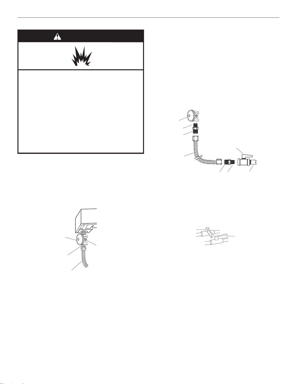
To Assemble Pressure Regulator:
1. Using two or more people, stand the cooktop on its side
orback.
2. Connect the exible stainless steel connector to the pressure
regulator using a 1/2" (1.3 cm) male pipe thread adapter.
A combination of pipe ttings must be used to connect the
cooktop to the existing gas line. The following shows a
typical connection. Your connection may be different,
according to the supply line type, size, and location.
4. Place cooktop into the countertop cutout.
NOTE: Check that the front edge of the cooktop is parallel
tothe front edge of the countertop. If repositioning
is needed, lift entire cooktop up from cutout to avoid
scratching the countertop.
Typical flexible connection
1. Apply pipe-joint compound made for use with Propane gas
to the smaller thread ends of the exible connector adapters
(see Band F in the following illustration).
2. Attach one adapter to the gas pressure regulator and
the other adapter to the gas shut-off valve. Tighten both
adapters.
3. Use a 15/16" (2.4 cm) combination wrench and channel lock
pliers to attach the exible connector to the adapters. Check
that connector is not kinked.
B
C
H
D
A. Gas pressure regulator
B. Use pipe-joint compound.
C. Adapter - must have 1/2"
(1.3 cm) male pipe thread
D. Flexible connector
E
E. Adapter
F. Use pipe-joint compound.
G. 1/2" (1.3 cm) or 3/4"
(1.9 cm) gas pipe
H. Manual gas shut-off valve
G
Complete Connection
1. Open the manual shut-off valve in the gas supply line. The
valve is open when the handle is parallel to the gas pipe.
C
A. Gas pressure regulator
B. Regulator - Must be installed with arrow pointing up
to cooktop bottom
C. Adapter - Must have 1/2" (1.3 cm) male pipe thread
D. CSA approved flexible stainless steel gas supply line
3. Install the pressure regulator with the arrow pointing up
toward the bottom of the cooktop burner base and in a
position where you can reach the regulator cap.
IMPORTANT: All connections must be wrench-tightened.
Donot make connections to the gas regulator too tight.
Making the connections too tight may crack the regulator
and cause a gas leak. Do not allow the regulator to turn on
the pipe when tightening ttings.
Use only pipe-joint compound made for use with Natural
andPropane gas. Do not use TEFLON® tape.
You will need to determine the ttings required depending
onyour installation.
16-Jan-2019 04:15:35 EST | RELEASED
B
A. Closed valve
B. Open valve
2. Test all connections by brushing on an approved
noncorrosive leak-detection solution. If bubbles appear,
aleak is indicated. Correct any leak found.
3. Remove cooktop burner caps, and grates from parts
package. Place burner caps on burner bases. Place grates
over burners andcaps.
In some European factories the letter "W" of the part code mentioned herein will be automatically
replaced by the number "4000" (e.g. "W12345678" becomes "400012345678")
11
Page 12

Complete Installation
B
A
Install Burner Caps
Place burner caps on top of burner bases. If burner caps are not
properly positioned, surfaceburners will not light.
Burner
A
A. Incorrect
B. Correct
B
Electronic Ignition System
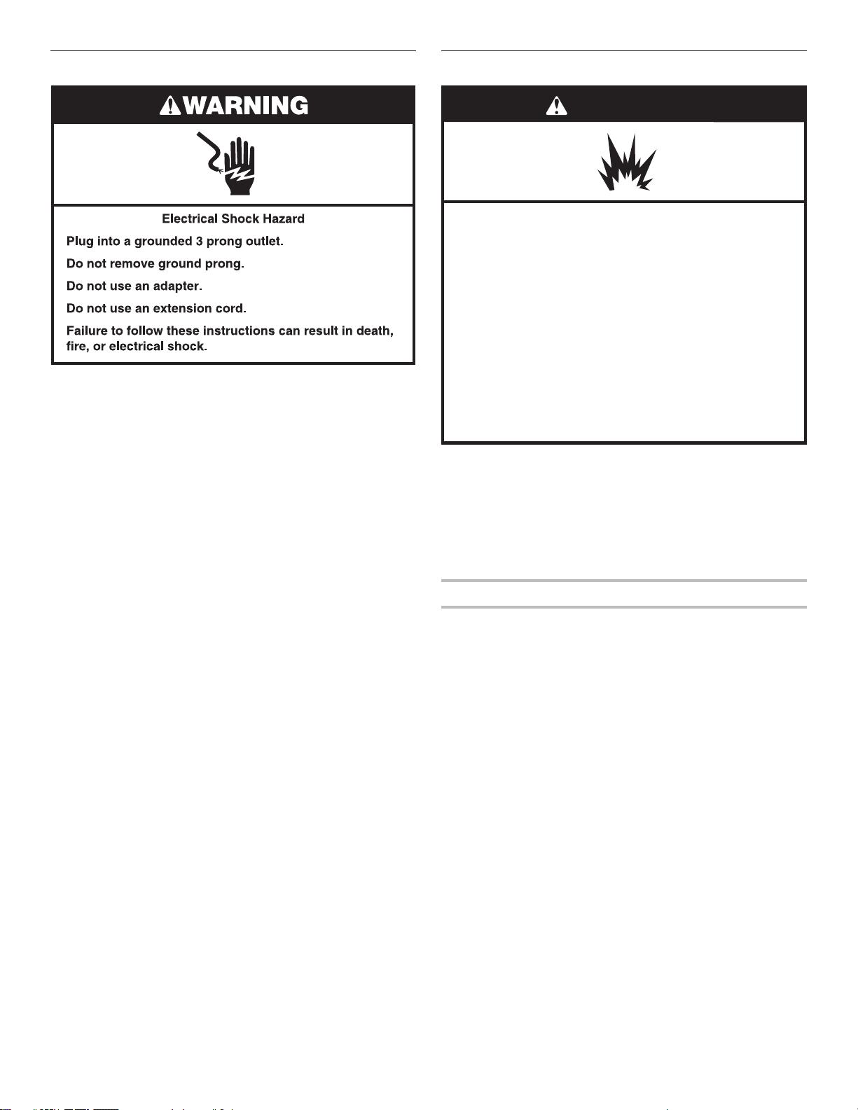
4. Plug into a grounded 3 prong outlet.
5. Check the operation of the surface burners. See “Check
Operation of Cooktop Burners” section in the “Complete
Installation” section.
6. If your model has a griddle, see the “Install Griddle Tray”
section.
Install Griddle Tray
(on griddle models)
The griddle is factory installed.
1. Place drip tray in the well at the front of the griddle. Slide tray
toward the back until it stops.
A
B
A. Griddle drip tray
B. Griddle
2. Clean griddle before using. Refer to the Use and Care Guide.
Initial lighting and gas flame adjustments
Cooktop burners use electronic igniters in place of standing
pilots. When the cooktop control knob is turned to any position,
the system creates a spark to light the burner. This sparking
continues until the ame is lit or the knob is turned to OFF.
Check Operation of Cooktop Burners
Push in and turn each control knob to the IGNITE position.
The surface burners and grill ames should light within
4seconds. The rst time a burner is lit, it may take longer
than4seconds to light because of air in the gas line.
After verifying the proper burner operation, turn the control
knobs to OFF.
If burners do not light properly:
■ Turn cooktop control knob to the OFF position.
■ Check that the cooktop is plugged in and the circuit breaker
has not tripped or the fuse has not blown.
■ Check that the gas shut-off valves are set to the
“open”position.
■ Check that burner caps are properly positioned on
burnerbases.
Repeat start-up. If a burner does not light at this point, contact
your dealer or authorized service company for assistance.
If you need Assistance or Service:
Please reference the “Assistance or Service” section of the Use
and Care Guide or contact the dealer from whom you purchased
your cooktop.
Flame Height
12
16-Jan-2019 04:15:35 EST | RELEASED
The cooktop ame should be a steady blue ame.
NOTE: Flame heights are factory set. If they don’t appear
correct, please contact your service provider.
Burner
A. Upper (main) flame
B. Lower (simmer) flame
In some European factories the letter "W" of the part code mentioned herein will be automatically
replaced by the number "4000" (e.g. "W12345678" becomes "400012345678")
Page 13

GAS CONVERSIONS
A
B
C
C
DE
IMPORTANT: Gas conversions from Natural gas to Propane gas
must be done by a qualied installer.
WARNING
Explosion Hazard
Use a new CSA International approved gas supply line.
Install a shut-off valve.
Securely tighten all gas connections.
If connected to propane, have a qualified person make
sure gas pressure does not exceed 14" (36 cm) water
column.
Examples of a qualified person include:
licensed heating personnel,
authorized gas company personnel, and
authorized service personnel.
Failure to do so can result in death, explosion, or fire.
To Convert Gas Pressure Regulator from Natural Gas
to Propane
1. Remove the gas pressure regulator cap by using a
large at-blade screwdriver, turning the regulator cap
counterclockwise. When the cap is removed, do not lose the
metal seal.
NOTE: Do not remove the spring beneath the cap.
2. Remove spring retainer from the cap by turning the spring
retainer counterclockwise. Locate the “LP” and “NAT”
position on the spring retainer. Turn over the spring retainer so
the “LP” arrow is pointing toward the cap.
A
LP
B
NAT
LP
NAT
NAT
LP
NAT
LP
Propane Gas Conversion
1. Turn the manual shut-off valve to the closed position.
A. To cooktop
B. Shut-off valve (closed position)
C. Gas supply line
2. Unplug cooktop or disconnect power.
A. Regulator cap
B. Metal seal
C. Gas pressure regulator
D. Spring retainer in NAT
position
E. Spring retainer in LP
position
3. Tighten the gas pressure regulator cap by using a large at
blade screwdriver, turning the regulator cap clockwise.
4. Test the gas pressure regulator and gas supply line.
The regulator must be checked at a minimum 1" (2.5 cm)
water column above the set pressure. The inlet pressure
tothe regulator should be as follows for operation and
checking the regulator setting:
Propane Gas:
Minimum pressure: 10" (25.4 cm) WCP
Maximum pressure: 14" (35.6 cm) WCP
Gas Supply Pressure Testing
Gas supply pressure for testing regulator must be at least 1"
(2.5 cm) water column pressure above the manifold pressure
shown on the model/serial/rating plate.
Line pressure testing above 1/2 psi (3.5 kPa) gauge (14"
[35.6cm] WCP)
The cooktop and its individual shut-off valve must be
disconnected from the gas supply piping system during
anypressure testing of that system at test pressures in
excess of 1/2 psi (3.5 kPa).
Line pressure testing at 1/2 psi (3.5 kPa) gauge (14"
[35.6cm]WCP) or lower
The cooktop must be isolated from the gas supply piping
system by closing its individual manual shut-off valve during
any pressure testing of the gas supply piping system at test
pressures equal to or less than 1/2 psi (3.5 kPa).
16-Jan-2019 04:15:35 EST | RELEASED
In some European factories the letter "W" of the part code mentioned herein will be automatically
replaced by the number "4000" (e.g. "W12345678" becomes "400012345678")
13
Page 14

To Convert Surface Burners
A
A
B
AB
Console attachment
1. If installed, remove the burner grates.
2. Remove burner cap.
3. Remove the burner base by rst removing (2) T-20 screws.
Burner
A. Burner cap
B
B. Screws
C
C. Burner base
4. Apply masking tape to the end of a 1/4" (7 mm) nut driver
to help hold the gas orice spud in the nut driver while
changing it. Insert nut driver into gas opening and press
down onto the gas orice spud, and remove by turning the
gas orice spud counterclockwise and lifting out. Set gas
orice spud aside.
5. Replace with correct Propane gas orice spud. See the
“Propane Gas Orice Spud/Hood Chart.”
Burner orifice spud
A. Size stamp
B. Fuel type stamp (L for Propane or
N for Natural gas)
Use the following chart to nd the exact orice spud placement.
Propane Gas Orifice Spud/Hood Chart
Burner
Rating
7,400 BTUs 70
13,000 BTUs 99
Stamp Size Burner Style
44
50
0.70 mm
0.44 mm
0.99 mm
0.50 mm
Small burner - main
Small burner - simmer
Large burner - main
Large burner - simmer
Adjusting Simmer Low Setting on Surface Burner for
Propane
1. Locate the Simmer low-turndown adjustment screw through
the bezel on the left side of the ignition switch.
A. Simmer low-turndown adjustment screw
B. Ignition switch
2. With the burner ON, and set to Simmer Lo, adjust the
simmer ame down to the proper BTU level. Using a
1/8" x 4
1
4
/
" (3.2 mm x 108 mm) at blade screwdriver, turn
the simmer low-turndown adjustment screw clockwise until
the ame height is below the bottom of the cap. If the ame
becomes unstable and ickers or appears to race around the
burner, the adjustment is too low and the screw should be
adjusted counterclockwise until the ame is stable. Repeat
this step for all surface burners, except the grill burner.
NOTE: Use a knob to adjust the burner valve.
NOTE: If your cooktop has the IR grill, then skip ahead to
Convert IR Grill Burner section.
3. Replace the bezels using the 2 screws which attach to the
valve brackets.
NOTE: Make sure no wires are pinched when reinstalling
bezels.
4. Push the surface knobs onto the valve stems.
5. Replace burner grates.
To Convert IR Grill Burner for Propane
1. Unplug or disconnect power.
2. Remove the grill knob and bezel. The other surface knobs
and bezels should be off the cooktop.
3. Remove the two screws on each side of the cooktop that
hold the control console in place.
16,000 BTUs 116 1.16 mm Grill burner
NOTE: Refer to serial tag for more information on burner ratings
and locations.
6. Place Natural gas orice spuds in plastic parts bag for future
use and keep with package containing literature.
NOTE: There may be extra orices in your kit.
7. Replace the burner base and screws. Tighten screws only
until burner is snug to cooktop, do not over-tighten.
8. Replace burner cap.
9. Repeat steps 2 through 8 for the remaining burners.
10. Remove the control knobs and bezels for surface burners
and grill.
NOTE: For oven controls and griddle controls, no changes
are needed.
14
16-Jan-2019 04:15:35 EST | RELEASED
screws (2 per side)
Do not remove
this screw
4. Pull up on console and slide out from cooktop. Disconnect
griddle switch connectors and lights, if applicable. Set
console in safe place.
In some European factories the letter "W" of the part code mentioned herein will be automatically
replaced by the number "4000" (e.g. "W12345678" becomes "400012345678")
Page 15

5. Remove two screws holding grill orice holder bracket.
ve/replace
A
B
C
A
B
A
9. Lift up on the control console and set it back into place. For
a proper t, the ange of the control console must hook over
the lip on the front of the cooktop.
NOTE: The side ange of the console aligns outside of the
cooktop box, but inside the side rail ange.
B
A. Screws
B. Grill orifice holder bracket
A
6. Pull the grill orice holder out of the burner box to allow
access to the orice with a wrench, being certain not to kink
the attached tubing.
A
B
A. Grill orifice
B. Grill orifice holder
A. Side rail flange
B. Console side flange
C. Cooktop box
NOTE: It may be necessary to lift valve stems to align with
console holes.
A. Control console flange
B. Front lip of range cooktop
10. Check that the control console is ush with the top edge of
the cooktop.
7. Using an adjustable wrench and a 1/2” (1.3 cm) open end
wrench remove the Natural gas orice spud and replace with
the correct Propane orice spud.
8. Reposition the grill orice holder assembly back into the
burner box, and replace the grill orice holder bracket and
16-Jan-2019 04:15:35 EST | RELEASED
two holder screws.
Use 1/2" (1.3 cm)
open end wrench
to remo
orifice
Hold with adjustable
wrench here
In some European factories the letter "W" of the part code mentioned herein will be automatically
A. Flush with range top
11. Replace the screws on each side of the control console.
12. Replace the control knobs and bezels.
13. Replace burner grates.
14. Reconnect power.
Complete Installation
1. Refer to the “Make Gas Connection” section for properly
connecting the cooktop to the gas supply.
2. Refer to the “Electronic Ignition System” section for proper
burner ignition, operation, and burner ame adjustments.
IMPORTANT: You may have to adjust the LO setting for each
cooktop burner.
Checking for proper cooktop burner ame is very important.
The small inner cone should have a very distinct blue ame
1/4" (6.4 mm) to 1/2" (1.3 cm) long. The outer cone is not as
distinct as the inner cone. Propane gas ames have a slightly
yellow tip.
3. Refer to the “Complete Installation” section in the
“Installation Instructions” section of these instructions to
complete this procedure.
15
replaced by the number "4000" (e.g. "W12345678" becomes "400012345678")
Page 16

Natural Gas Conversion
A
B
C
C
DE
A
B
1. Turn the manual shut-off valve to the closed position.
A. To cooktop
B. Shut-off valve (closed position)
C. Gas supply line
2. Unplug cooktop or disconnect power.
To Convert Gas Pressure Regulator
1. Remove the gas pressure regulator cap by using a
large at-blade screwdriver, turning the regulator cap
counterclockwise. When the cap is removed, do not lose the
metal seal.
2. Remove spring retainer from the cap by turning the spring
retainer counterclockwise. Locate the “LP” and “NAT”
position on the spring retainer. Turn over the spring retainer
so the “NAT” arrow is pointing toward the cap.
4. Test the gas pressure regulator and gas supply line.
The regulator must be checked at a minimum 1" (2.5 cm)
water column above the set pressure. The inlet pressure
tothe regulator should be as follows for operation and
checking the regulator setting:
Natural Gas:
Minimum pressure: 5" (12.7 cm) WCP
Maximum pressure: 14" (35.6 cm) WCP
Gas Supply Pressure Testing
Gas supply pressure for testing regulator must be at least 1"
(2.5 cm) water column pressure above the manifold pressure
shown on the model/serial/rating plate.
Line pressure testing above 1/2 psi (3.5 kPa) gauge (14"
[35.6cm] WCP)
The cooktop and its individual shut-off valve must be
disconnected from the gas supply piping system during
anypressure testing of that system at test pressures in
excess of 1/2 psi (3.5 kPa).
Line pressure testing at 1/2 psi (3.5 kPa) gauge (14"
[35.6cm]WCP) or lower
The cooktop must be isolated from the gas supply piping
system by closing its individual manual shut-off valve during
any pressure testing of the gas supply piping system at test
pressures equal to or less than 1/2 psi (3.5 kPa).
To Convert Surface Burners
A
B
A. Regulator cap
B. Metal seal
C. Gas pressure regulator
NAT
LP
NAT
LP
D. Spring retainer in LP
position
E. Spring retainer in NAT
position
LP
NAT
LP
NAT
3. Tighten the gas pressure regulator cap by using a large
at-blade screwdriver, turning the regulator cap clockwise.
1. If installed, remove the burner grates.
2. Remove burner cap.
3. Remove the burner base.
Burner
A
A. Burner cap
B
B. Screws
C
C. Burner base
4. Apply masking tape to the end of a 1/4" (7 mm) nut driver
to help hold the gas orice spud in the nut driver while
changing it. Insert nut driver into gas opening and press
down onto the gas orice spud and remove by turning the
gas orice spud counterclockwise and lifting out. Set gas
orice spud aside.
5. Replace with correct Natural gas orice spud. See the
“Natural Gas Orice Spud/Hood Chart.”
Burner orifice spud
A. Size stamp
B. Fuel type stamp (L for Propane or
N for Natural gas)
16
16-Jan-2019 04:15:35 EST | RELEASED
In some European factories the letter "W" of the part code mentioned herein will be automatically
replaced by the number "4000" (e.g. "W12345678" becomes "400012345678")
Page 17

Use the following chart to nd the exact orice spud placement.
AB
Console attachment
Natural Gas Orifice Spud/Hood Chart
Burner
Rating
9,200 BTUs 130
18,000 BTUs
(REAR)
20,000 BTUs
(FRONT)
Stamp Size Burner Style
70
193
78
203
78
1.30 mm
0.70 mm
1.93 mm
0.78 mm
2.03 mm
0.78 mm
Small burner - main
Small burner - simmer
Large burner – main
Large burner – simmer
Large burner – main
Large burner – simmer
16,000 BTUs 180 1.80 mm Grill burner
NOTE: Refer to serial tag for more information on burner ratings
and locations.
6. Place Propane gas orice spuds in plastic parts bag for
future use and keep with package containing literature.
NOTE: There may be extra orices in your kit.
7. Replace the burner base and screws. Tighten screws only
until burner is snug to cooktop, do not over-tighten.
8. Replace burner cap.
9. Repeat steps 2 through 8 for the remaining burners.
4. Replace the bezels using the 2 screws which attach to the
valve brackets.
NOTE: Make sure no wires are pinched when reinstalling
bezels.
5. Push the surface knobs onto the valve stems.
6. Replace burner grates.
To Convert IR Grill Burner for Natural Gas
1. Unplug range or disconnect power.
2. Remove grill knob and bezel. The other surface knobs and
bezels should still be off the cooktop.
3. Remove the two screws on each side of the cooktop that
hold the control console in place.
screws (2 per side)
Do not remove
this screw
4. Pull up on console and slide out from cooktop. Disconnect
griddle switch connectors and lights, if applicable. Set
console in safe place.
5. Remove the two screws holding the grill orice holder
bracket.
Adjusting Simmer Low Setting on Surface Burner for
Natural Gas
1. Remove the surface burner control knobs and bezels (griddle
control knob does not have to be removed).
2. Locate the Simmer low-turndown adjustment screw through
the bezel on the left side of the ignition switch.
3. With the burner ON, and set to Simmer Lo, adjust the
simmer ame down to the proper BTU level. Using a
1/8" x 4
turn the simmer low-turndown adjustment screw
counterclockwise until the ame becomes stable, does not
icker, or appear to race around the burner. Once the ame
is stable, turn the burner rate to SIMMER HIGH setting. The
ame should increase to approximately 2X the ame height.
If not, the low-turndown may be able to be adjusted low and
still remain stable. Repeat this step for all surface burners,
except the grill burner.
NOTE: Use a knob to adjust the burner valve.
NOTE: If your cooktop has the IR grill, then skip ahead to the
Convert IR Grill Burner section.
A. Simmer low-turndown adjustment screw
B. Ignition switch
1
4
/
" (3.2 mm x 108 mm) at blade screwdriver,
B
A. Screws
B. Grill orifice holder bracket
A
16-Jan-2019 04:15:35 EST | RELEASED
In some European factories the letter "W" of the part code mentioned herein will be automatically
replaced by the number "4000" (e.g. "W12345678" becomes "400012345678")
17
Page 18

6. Pull the grill orice holder out of the burner box to allow
ve/replace
A
B
C
A
B
A
access to the orice with a wrench, being certain not to kink
the attached tubing.
A
B
A. Grill orifice
B. Grill orifice holder
7. Using an adjustable wrench and a 1/2" (1.3 cm) open end
wrench remove the Propane (L) orice spud and replace with
the correct Natural Gas (NG) orice spud. See Natural Gas
Orice Spud Chart.
NOTE: It may be necessary to lift valve stems to align with
console holes.
A. Control console flange
B. Front lip of range cooktop
10. Check that the control console is ush with the top edge of
the cooktop.
A. Flush with range top
Use 1/2" (1.3 cm)
open end wrench
to remo
orifice
Hold with adjustable
wrench here
8. Reposition the grill orice holder assembly back into the
burner box, and replace the grill orice holder bracket and
two holder screws.
9. Lift up on the control console and set it back into place. For
a proper t, the ange of the control console must hook over
the lip on the front of the cooktop.
NOTE: The side ange of the console aligns outside of the
cooktop box, but inside the side rail ange.
11. Replace the screws on each side of the control console.
12. Replace the control knobs and bezels.
13. Replace burner grates.
14. Reconnect power.
Complete Installation
1. Refer to the “Make Gas Connection” section for properly
connecting the cooktop to the gas supply.
2. Refer to the “Electronic Ignition System” section for proper
burner ignition, operation, and burner ame adjustments.
Checking for proper cooktop burner ame is very important.
The small inner cone should have a very distinct blue ame
1/4" (6.4 mm) to 1/2" (1.3 cm) long. The outer cone is not as
distinct as the inner cone. Propane gas ames have a slightly
yellow tip.
3. Refer to “Complete Installation” in the “Installation
Instructions” section of these instructions to complete this
procedure.
A. Side rail flange
B. Console side flange
18
16-Jan-2019 04:15:35 EST | RELEASED
C. Cooktop box
In some European factories the letter "W" of the part code mentioned herein will be automatically
replaced by the number "4000" (e.g. "W12345678" becomes "400012345678")
Page 19

SÉCURITÉ DE LA TABLE DE CUISSON
Votre sécurité et celle des autres est très importante.
Nous donnons de nombreux messages de sécurité importants dans ce manuel et sur votre appareil ménager. Assurez-vous de
toujours lire tous les messages de sécurité et de vous y conformer.
Voici le symbole d’alerte de sécurité.
Ce symbole d’alerte de sécurité vous signale les dangers potentiels de décès et de blessures graves à vous
et à d’autres.
Tous les messages de sécurité suivront le symbole d’alerte de sécurité et le mot “DANGER” ou
“AVERTISSEMENT”. Ces mots signifient :
Risque possible de décès ou de blessure grave si vous ne
DANGER
AVERTISSEMENT
Tous les messages de sécurité vous diront quel est le danger potentiel et vous disent comment réduire le risque de blessure et
ce qui peut se produire en cas de non-respect des instructions.
AVERTISSEMENT : Si les renseignements dans ces instructions ne sont pas
exactement observés, un incendie ou une explosion peut survenir, causant des
dommages au produit, des blessures ou un décès.
suivez pas immédiatement les instructions.
Risque possible de décès ou de blessure grave si vous
ne suivez pas les instructions.
– Ne pas entreposer ni utiliser de l’essence ou d’autres vapeurs ou liquides inflammables
à proximité de cet appareil ou de tout autre appareil électroménager.
– QUE FAIRE DANS LE CAS D’UNE ODEUR DE GAZ :
Ne pas tenter d’allumer un appareil.
•
Ne pas toucher à un commutateur électrique.
•
Ne pas utiliser le téléphone se trouvant sur les lieux.
•
Appeler immédiatement le fournisseur de gaz à partir du téléphone d'un voisin. Suivre
•
ses instructions.
À défaut de joindre votre fournisseur de gaz, appeler les pompiers.
•
– L’installation et l’entretien doivent être effectués par un installateur qualifié, une agence
de service ou le fournisseur de gaz.
AVERTISSEMENT : L’odorat ne permet pas toujours la détection d’une fuite de gaz.
Les distributeurs de gaz recommandent l’emploi d’un détecteur de gaz (homologation UL ou CSA).
Pour d'autres informations, contacter le fournisseur de gaz local.
En cas de détection d’une fuite de gaz, exécuter les instructions “Que faire dans le cas d’une odeur de gaz”.
16-Jan-2019 04:15:35 EST | RELEASED
In some European factories the letter "W" of the part code mentioned herein will be automatically
replaced by the number "4000" (e.g. "W12345678" becomes "400012345678")
19
Page 20

IMPORTANT : Ne pas installer un système de ventilation avec évacuation de l'air vers le bas, qui évacuerait l'air vers cet
appareil de cuisson à gaz. Ce type de système de ventilation peut causer des problèmes d'allumage et de combustion avec cet
appareil de cuisson à gaz et entraîner des blessures corporelles ou le fonctionnement non désiré de cet appareil.
Dans l’État du Massachusetts, les instructions d’installation suivantes sont applicables :
■ Les travaux d’installation et réparation doivent être exécutés par un plombier ou tuyauteur qualifié ou licencié, ou par le
personnel qualifié d’une entreprise licenciée par l’État du Massachusetts.
■ Remplacer par des dispositifs de fermeture acceptables : Les robinets de gaz et robinets à bille installés pour l'utilisation
devraient être indiqués.
■ Si un conduit de raccordement flexible est utilisé, sa longueur ne doit pas dépasser 4 pi (121,9 cm).
EXIGENCES D’INSTALLATION
Outils et pièces
Rassembler les outils et pièces nécessaires avant d’entreprendre l’installation. Lire et observer les instructions fournies avec chacun
des outils de la liste ci-dessous.
Outils nécessaires
Clé à molette Ruban à mesurer Marqueur ou crayon
Clé à tuyauterie Tournevis à tête plate Clé mixte de 15/16 po (24 mm)
Clé ou pince multiprise Composé d’étanchéité des raccords
Pour les conversions gaz propane/naturel
Clé à molette Clé à cliquet Grand tournevis à lame plate
filetés résistant au gaz propane
Solution non corrosive de détection des
fuites
Tournevis Torx T-20 Ruban adhésif de masquage Clé ouverte de 1/2 po (1,3 cm)
20
16-Jan-2019 04:15:35 EST | RELEASED
In some European factories the letter "W" of the part code mentioned herein will be automatically
replaced by the number "4000" (e.g. "W12345678" becomes "400012345678")
Page 21

Pièces fournies
Vérier que toutes les pièces sont présentes.
■ Détendeur
■ Grilles de brûleur
■ Chapeaux de brûleur
■ Plateau d’égouttement de la plaque à frire (sur modèles avec
plaque à frire)
■ Ruban mousse
Pièces nécessaires
Tous les modèles doivent être installés avec un dosseret si
l’installation se fait sans dégagement entre l’appareil et une paroi
arrière combustible. Voir le point “Dimensions de l’armoire” à
la section “Exigences d’emplacement” pour les spécications
concernant l’installation.
Pour commander, voir la section “Assistance ou service” du Guide
d’utilisation et d’entretien.
Vérier les codes locaux et consulter le fournisseur de gaz.
Vérier l’alimentation en gaz et l’alimentation électrique existantes.
Voir les sections “Spécications électriques” et “Spécications de
l’alimentation en gaz”.
Conversion pour utilisation en haute altitude
Pour convertir la table de cuisson pour des altitudes supérieures
à 6560pi (2000m), commander un ensemble pour conversion
en haute altitude.
■ Pièce numéroW11238043: Ensemble pour l’utilisation à une
altitude élevée
REMARQUE: Les éléments de conversion pour l’alimentation
au gaz naturel ou au propane sont inclus dans l’ensemble pour
l’utilisation à une altitude élevée.
Pour commander, voir la section “Assistance ou service” du
Guide d’utilisation et d’entretien.
REMARQUE: La table de cuisson est conçue pour une
utilisation au gaz naturel. Pour effectuer une conversion au gaz
propane, voir la section “Conversions pour changement de gaz”.
Exigences d’emplacement
IMPORTANT: Observer les dispositions de tous les codes et
règlements en vigueur. Ne pas obstruer le ux de combustion
etde ventilation.
■ C’est à l’installateur qu’incombe la responsabilité de respecter
les distances de séparation spéciées sur la plaque signalétique.
La plaque signalétique des numéros de modèle et de série est
située sur la face inférieure de la base de brûleur de la table de
cuisson.
■ Il est recommandé qu’une hotte de 600 CFM (17,0m
plus soit installée au-dessus de la table de cuisson.
■ Suivreles instructions d’installation de la hotte de cuisinière
ou de l’ensemble hotte/micro-ondes pour les dimensions de
dégagement à respecter au-dessus de la surface de la table
de cuisson.
■ La table de cuisson doit être installée dans un emplacement
à l’écart des zones de forts courants d’air, telles que fenêtres,
portes et évents ou ventilateurs de chauffage.
■ Toutes les ouvertures dans le mur ou le plancher de
l’emplacement d’installation de la table de cuisson doivent
être scellées.
■ Respecter les dimensions indiquées pour les ouvertures à
découper dans les meubles. Ces dimensions constituent les
valeurs minimums des dégagements.
■ Une source d’électricité avec liaison à la terre est nécessaire.
Voir la section “Spécications électriques”.
■ Un raccordement adéquat à l’alimentation en gaz doit être
disponible. Voir la section “Spécications de l’alimentation
en gaz”.
■ De par sa conception, la table de cuisson est conçue pour
être soutenue par un plancher solide dans l’ouverture, pas
retenue sur le plan de travail par ses rebords latéraux ou
arrière.
■ Les sources de gaz et d’électricité doivent être situées comme
indiqué à la section “Emplacements des raccordements au
gaz et à l’électricité”, pour qu’elles soient accessibles et qu’il
ne soit pas nécessaire d’enlever la table de cuisson.
■ Prévoir une ouverture dans l’angle arrière gauche de l’enceinte
– voir l’illustration – pour le passage de la canalisation de gaz
et du câble d’alimentation électrique et pour que l’étiquette
signalétique soit visible.
IMPORTANT: Pour éviter d’endommager les armoires, consulter
le constructeur de la maison ou le fabricant des armoires pour
déterminer si les matériaux utilisés peuvent subir un changement
de couleur, une déstratication ou d’autres dommages.
3
/h) ou
16-Jan-2019 04:15:35 EST | RELEASED
Résidence mobile – Spécifications additionnelles à
respecter lors de l’installation
L’installation de cette table de cuisson doit être conforme aux
dispositions de la norme Manufactured Home Construction and
Safety Standard, Title24 CFR, Part3280 (anciennement Federal
Standard for Mobile Home Construction and Safety, Title24,
HUD Part280).Lorsque cette norme n’est pas applicable,
utiliser la norme Standard for Manufactured Home Installations,
ANSIA225.1/NFPA501A ou les dispositions des codes locaux.
Au Canada, l’installation de cette table de cuisson doit satisfaire
aux stipulations de la version la plus récente de la norme CAN/
CSA-A240 ou des codes locaux en vigueur.
In some European factories the letter "W" of the part code mentioned herein will be automatically
replaced by the number "4000" (e.g. "W12345678" becomes "400012345678")
21
Page 22

Dimensions du produit
C
D
A
REMARQUE: Les caractéristiques de la table de cuisson peuvent varier.
Modèles de 30 po (76,2 cm)
A. 27 1/8 po (68,9 cm)
B. 29 7/8 po (75,9 cm)
Vue latérale de la table de cuisson
A
B
C. Cordon d’alimentation à 3 broches avec mise à
la terre
D. La plaque signalétique des numéros de modèle
et de série est située sur la face inférieure de la
base de brûleur de la table de cuisson
B
C
D
F
G
E
A. 27 3/8 po (69,5 cm)
B. 1 1/4 po (3,2 cm)
C. Garniture d’îlot ou dosseret facultatif
D. 77/16 po (18,8 cm)
E. L’entrée de gaz se trouve à 1 7/8 po (4,8 cm)
de l’arrière de la base du brûleur de la table
de cuisson et à 4 7/8 po (12,4 cm) du côté
intérieur gauche de la base du brûleur de la
table de cuisson.
F. 22 po (55,9 cm)
G. 35/16 po (8,4 cm)
22
16-Jan-2019 04:15:35 EST | RELEASED
In some European factories the letter "W" of the part code mentioned herein will be automatically
replaced by the number "4000" (e.g. "W12345678" becomes "400012345678")
Page 23

Modèles de 36 po (91,4 cm)
C
D
A. 27 1/8 po (68,9 cm)
B. 35 3/4 po (90,8 cm)
Vue latérale de la table de cuisson
A
C. Cordon d’alimentation à 3 broches avec mise à la terre
D. La plaque signalétique des numéros de modèle et
de série est située sur la face inférieure de la base de
brûleur de la table de cuisson
B
A
B
C
G
A. 27 3/8 po (69,5 cm)
B. 1 1/4 po (3,2 cm)
C. Garniture d’îlot ou dosseret facultatif
D. 77/16 po (18,8 cm)
D
F
E
E. L’entrée de gaz se trouve à 1 7/8 po (4,8 cm) de
l’arrière de la base du brûleur de la table de cuisson
et à 4 7/8 po (12,4 cm) du côté intérieur gauche de la
base du brûleur de la table de cuisson.
F. 22 po (55,9 cm)
G. 35/16 po (8,4 cm)
16-Jan-2019 04:15:35 EST | RELEASED
In some European factories the letter "W" of the part code mentioned herein will be automatically
replaced by the number "4000" (e.g. "W12345678" becomes "400012345678")
23
Page 24

Modèles de 48 po (121,9 cm)
D
A. 27 1/8 po (68,9 cm)
B. 47 7/8 po (121,6 cm)
Vue latérale de la table de cuisson
A
B
C
C. Cordon d’alimentation à 3 broches avec mise à la
terre
D. La plaque signalétique des numéros de modèle
et de série est située sur la face inférieure de la
base de brûleur de la table de cuisson
A
B
C
D
G
F
E
A. 27 3/8 po (69,5 cm)
B. 1 1/4 po (3,2 cm)
C. Garniture d’îlot ou dosseret facultatif
D. 77/16 po (18,8 cm)
E. L’entrée de gaz se trouve à 1 7/8 po (4,8 cm)
de ’arrière de la base du brûleur de la table de
cuisson et à 4 7/8 po (12,4 cm) du côté intérieur
gauche de la base du brûleur de la table de
cuisson.
F. 22 po (55,9 cm)
G. 35/16 po (8,4 cm)
24
16-Jan-2019 04:15:35 EST | RELEASED
In some European factories the letter "W" of the part code mentioned herein will be automatically
replaced by the number "4000" (e.g. "W12345678" becomes "400012345678")
Page 25

Emplacements des raccordements au gaz et à l’électricité
A. La prise de courant à 3 alvéoles reliée à la terre doit
se trouver du côté gauche de l’ouverture découpée,
à 16 po (40,6 cm) max de la paroi latérale de
l’encastrement
B. Dégagement minimal de 10 po (25,4 cm) à partir
du plan de travail jusqu’au sommet de la sortie
C. 14 po (35,6 cm) entre le plan de travail et la
canalisation d’alimentation en gaz
B
C
A
D. La canalisation d’alimentation en gaz doit se trouver
dans cette zone sur les murs arrière ou latéraux ;
la canalisation d’alimentation en gaz peut aussi
ressortir à travers le plancher.
REMARQUE : Le côté plein et le fond de
l’ouverture ne sont pas illustrés.
D
Spécifications de l’armoire
IMPORTANT: Lors de l’installation d’une hotte ou d’un ensemble hotte/four à micro-ondes au-dessus de la surface de cuisson,
suivre les instructions fournies avec la hotte ou l’ensemble hotte/micro-ondes concernant les dimensions de dégagement à
respecter au-dessus de la surface de la table de cuisson.
C
P
F
C
O
D
G
A*
B min.**
L
N
E
J
H
I
K
L
M
D
E
A. Voir le tableau.
B. Voir le tableau.
C. Voir le tableau.
D. Voir le tableau.
E. Voir le tableau.
F. Dégagement minimal de 18 po (45,7 cm) entre
l’armoire supérieure et le comptoir
G. 3/4 po (19 mm) entre l’arrière de l’ouverture
découpée dans l’armoire et l’ouverture
découpée pour la canalisation de gaz
H. 6 7/8 po (16,1 cm) de profondeur pour l’ouverture
découpée pour la canalisation de gaz
I. 12 1/2 po (31,7 cm) de largeur pour l’ouverture
découpée pour la canalisation de gaz
J. 22 1/4 po (56,5 cm) de profondeur de l’ouverture
découpée dans l’armoire
K. 2 po (5,1 cm) entre le côté de l’armoire et
l’ouverture découpée pour la canalisation de
gaz
L. Dégagement de 6 po (15,2 cm) min entre les
deux côtés de la table de cuisson et les parois
latérales ou d’autres matériaux combustibles
situés au-dessus de la surface de cuisson
M. Profondeur de l’armoire 24 po (61,0 cm)
N. 7 1/4 po (18,4 cm) de profondeur entre l’armoire
et le plan de travail
O. L’encoche doit être la même des deux côtés
P. Profondeur des armoires supérieures : 13 po
(33,0 cm)
Taille A*
Ouverture découpée
pour la table de
cuisson jusqu’au
B**
Entre la table
de cuisson et
l’armoire
C
Ouvertures pour
dosseret facultatif et
armoire supérieure
D
Armoire et plan de
travail
E
Plan de travail
uniquement
mur arrière
30po (76,2cm) 1 3/4 po (4,4cm)* 42po (106,7cm) 30po (76,2cm) 29 1/4 po (74,3cm) 29 7/8 po(75,9cm)
sans dégagement
36po (91,4cm) 1 3/4 po (4,4cm)* 58po (147,3cm) 36po (91,4cm) 35 1/4 po (89,5cm) 35 3/4 po(90,8cm)
sans dégagement
48po (121,9cm) 1 3/4 po (4,4cm)* 58po (147,3cm) 48po (121,9cm) 47 1/4 po (120,0cm) 47 7/8 po(121,6cm)
sans dégagement
* REMARQUE: Si le mur arrière est fabriqué d’un matériau combustible et qu’aucun dosseret n’est installé, un dégagement minimal
de la dimension A + 6po (15,2cm) est nécessaire pour tous les modèles.
16-Jan-2019 04:15:35 EST | RELEASED
In some European factories the letter "W" of the part code mentioned herein will be automatically
replaced by the number "4000" (e.g. "W12345678" becomes "400012345678")
25
Page 26

En cas d’installation d’une hotte au-dessus de la table de cuisson, suivre les instructions fournies avec la hotte concernant les
dimensions de dégagement à respecter au-dessus de la surface de la table de cuisson.
REMARQUE: En raison des tolérances de fabrication en usine, il s’agit de dimensions nominales. Il pourrait être nécessaire d’effectuer
des ajustements pour respecter votre dégagement.
Spécifications électriques
AVERTISSEMENT
Risque de choc électrique
Brancher sur une prise à 3 alvéoles reliée à la terre.
Ne pas enlever la broche de liaison à la terre.
Ne pas utiliser un adaptateur.
Ne pas utiliser un câble de rallonge.
Le non-respect de ces instructions peut causer
un décès, un incendie ou un choc électrique.
IMPORTANT: La table de cuisson doit être correctement reliée à la
terre en conformité avec les codes et règlements locaux en vigueur,
ou en l’absence de tels codes, avec le National Electrical Code,
ANSI/NFPA70 ou le Code canadien des installations électriques,
CSAC22.1.
Cette table de cuisson est dotée d’un système d’allumage
électronique qui ne fonctionnera pas en cas de branchement
dans une prise qui n’est pas correctement polarisée.
Si les codes le permettent et si on utilise un conducteur distinct
de liaison à la terre, il est recommandé qu’un électricien qualié
vérie la qualité de la liaison à la terre.
Pour obtenir un exemplaire des normes des codes ci-dessus,
contacter:
National Fire Protection Association
1 Batterymarch Park
Quincy, MA 02169-7471
CSA International
8501 East Pleasant Valley Road
Cleveland, Ohio44131-5575
■ L’appareil doit être alimenté par un circuit de 120 V CA à 60Hz
seulement et protégé par fusible de 15 A. On recommande
également d’utiliser un fusible ou un disjoncteur temporisé. Il
est recommandé de raccorder la table de cuisson sur un circuit
distinct exclusif à cet appareil.
■ Les systèmes d’allumage électronique fonctionnement avec
des limites de tension étendues, mais une liaison à la terre
correcte et une polarité appropriée sont nécessaires. Vérier
que la prise fournit une alimentation de 120 V et qu’elle est
correctement reliée à la terre.
■ Les schémas de câblage sont fournis avec cette cuisinière.
Les schémas de câblage se trouvent à l’intérieur de la
console de commande.
Spécifications de l’alimentation
en gaz
AVERTISSEMENT
Risque d'explosion
Utiliser une canalisation neuve d'arrivée de gaz
approuvée par la CSA International.
Installer un robinet d'arrêt.
Bien serrer chaque organe de connexion de la
canalisation de gaz.
En cas de connexion au gaz propane, demander à une
personne qualifiée de s'assurer que la pression de gaz
ne dépasse pas 36 cm (14 po) de la colonne d'eau.
Par personne qualifiée, on comprend :
le personnel autorisé de chauffage,
le personnel autorisé d'une compagnie de gaz, et
le personnel d'entretien autorisé.
Le non-respect de ces instructions peut causer
un décès, une explosion ou un incendie.
Observer les dispositions de tous les codes et règlements en
vigueur.
IMPORTANT: Cette installation doit être effectuée conformément
avec les codes et règlements locaux. En l’absence de codes
locaux, l’installation doit être effectuée en conformité avec l’édition
la plus récente du American National Standard, National Fuel Gas
Code ANSIZ223.1 ou l’édition la plus récente du CAN/CGA B149.
IMPORTANT: Des tests d’étanchéité doivent être effectués sur
la table de cuisson, conformément aux instructions du fabricant.
Type de gaz
Gaz naturel :
Cette table de cuisson a été congurée à l’usine pour l’alimentation
au gaz naturel. Pour effectuer une conversion au gaz propane,
voir la section “Conversions pour changement de gaz”. La plaque
signalétique des numéros de modèle et de série située du côté
gauche sous la base du brûleur de la table de cuisson indique les
types de gaz utilisables. Si la liste des gaz ne comprend pas le type
de gaz offert, vérier auprès du fournisseur de gaz local.
Conversion pour l’alimentation au propane :
L’opération de conversion doit être exécutée par un technicien
de réparation qualié.
Ne pas entreprendre de convertir la table de cuisson pour une
utilisation avec un gaz différent de celui indiqué sur la plaque
signalétique sans d’abord consulter le fournisseur de gaz. Pour
la conversion au gaz propane, utiliser la trousse de conversion
au gaz propane fournie avec la table de cuisson et voir la section
“Conversions pour changement de gaz”.
26
16-Jan-2019 04:15:35 EST | RELEASED
In some European factories the letter "W" of the part code mentioned herein will be automatically
replaced by the number "4000" (e.g. "W12345678" becomes "400012345678")
Page 27

Canalisation d’alimentation en gaz
A
C
Détendeur
■ Installer une canalisation de gaz rigide de 3/4po (1,9cm)
jusqu’à l’emplacement d’installation de la table de cuisson.
L’emploi d’une canalisation de diamètre inférieur sur un
circuit plus long peut causer une insufsance du débit
d’alimentation en gaz. Pour l’alimentation au propane, le
diamètre des canalisations ou tuyaux doit être de 1/2 po
(1,3cm) minimum. En général, le fournisseur de gaz propane
détermine les matériaux à utiliser et le diamètre approprié.
REMARQUE: On doit utiliser un composé d’étanchéité pour
tuyauteries résistant à l’action du gaz propane. Ne pas utiliser
de ruban TEFLON®†.
■ Raccord métallique flexible:
■ Si le code local le permet, on peut utiliser un raccord
métallique exible neuf (homologation CSA) de 4 à 5pi
(122 à 152cm) de longueur, diamètre interne 5/8 po
(1,6cm) ou 3/4 po (1,9cm), pour raccorder la table de
cuisson à la canalisation de gaz.
■ Un raccord de tuyauterie mâle de 1/2 po (1,3cm) est
nécessaire pour la connexion sur le raccord à letage
femelle à l’entrée du détendeur de l’appareil.
■ Ne pas déformer/écraser/endommager le tube métallique
exible lors d’un déplacement de la table de cuisson.
■ Robinet d’arrêt nécessaire:
Procéder à l’installation d’une vanne de fermeture manuelle
pour la conduite de gaz dans un endroit facile d’accès. Ne pas
entraver l’accès au robinet d’arrêt manuel. Le robinet d’arrêt
manuel est prévu pour ouvrir ou fermer l’alimentation en gaz
de la table de cuisson.
B
A. Canalisation de gaz
B. Robinet d’arrêt ouvert
C. Vers la table de cuisson
Le détendeur fourni avec cette table de cuisson doit être utilisé.
La pression d’alimentation du détendeur doit respecter les
indications suivantes pour obtenir un fonctionnement correct:
Gaz naturel :
Pression minimum: 5po (12,7cm) de colonne d’eau
Pression maximum: 14po (35,6cm) de colonne d’eau
Gaz propane :
Pression minimum: 10po (25,4cm) de colonne d’eau
Pression maximum: 14po (35,6cm) de colonne d’eau
Communiquer avec votre fournisseur local de gaz en cas de doute
sur la pression d’entrée.
Débit thermique des brûleurs – Altitude
Les débits thermiques indiqués sur la plaque signalétique
correspondent à une altitude d’utilisation inférieure à 2000pi
(609,6m).
Lorsque l’appareil est utilisé à une altitude supérieure à 2000pi
(609,6m), on doit réduire le débit thermique indiqué de 4% pour
chaque tranche de 1000pi (304,8m) au-dessus du niveau de la
mer (non applicable au Canada).
Essai de pression de la canalisation de gaz
On doit tester le détendeur sous une pression supérieure d’au
moins 1po (2,5cm) à la pression de la tubulure de distribution
indiquée sur la plaque signalétique.
Mise sous pression à une pression supérieure à 1/2 lb/po2
(3,5 kPa) (14 po [35,6 cm] de colonne d’eau)
Lors de tout test de pressurisation de ce système à une pression
supérieure à 1/2 lb/po² (3,5kPa), on doit déconnecter la table
de cuisson et son robinet d’arrêt individuel de la canalisation
degaz.
Mise sous pression à une pression de 1/2 lb/po² (3,5 kPa)
(14 po [35,6 cm] de colonne d’eau) ou moins
Lors de tout test de pressurisation de la canalisation de gaz à
une pression égale ou inférieure à 1/2 lb/po² (3,5kPa), on doit
isoler la table de cuisson de la canalisation de gaz par fermeture
de son robinet d’arrêt manuel individuel.
†® TEFLON est une marque déposée de Chemours.
16-Jan-2019 04:15:35 EST | RELEASED
In some European factories the letter "W" of the part code mentioned herein will be automatically
replaced by the number "4000" (e.g. "W12345678" becomes "400012345678")
27
Page 28

INSTRUCTIONS D’INSTALLATION
A
C
A
D
Installation de la table de cuisson
AVERTISSEMENT
Risque du poids excessif
Utiliser deux ou plus de personnes pour déplacer et
installer la table de cuisson.
Le non-respect de cette instruction peut causer
une blessure au dos ou d'autre blessure.
Prendre note des numéros de modèle et de série avant d’installer
la table de cuisson. Les deux numéros sont situés sur la partie
inférieure avant gauche de la base du brûleur.
Déballer les pièces fournies avec la table de cuisson.
Les pièces expédiées avec la table de cuisson dépendent du
modèle commandé. Voir la section “Outils et pièces” pour une
liste complète des pièces fournies avec votre table de cuisson.
Le détendeur et le connecteur de la canalisation de gaz exible
en acier inoxydable peuvent être raccordés à la table de cuisson
maintenant ou après l’installation de la table de cuisson dans
l’ouverture. Voir la section “Raccordement au gaz”.
1. Déterminer l’emplacement nal de la table de cuisson.
2. À l’aide de deux personnes ou plus, placer la table de
cuisson à l’envers sur une surface couverte.
Effectuer le raccordement au gaz
AVERTISSEMENT
3. Enlever la bande de mousse de l’emballage de documents.
Retirer l’endos de la bande de mousse. Appliquer le côté
adhésif de la bande en mousse le long des rives gauche et
droite de la garniture de table de cuisson, en progressant
vers le bas.
REMARQUE: La bande de mousse aide la table de cuisson
à rester à plat sur des comptoirs irréguliers et permet d’éviter
d’endommager la surface de la surface du plan de travail.
B
A. Base de la table de cuisson
B. Bande de mousse
C. Table de cuisson
4. En employant au moins deux personnes, mettre la table de
cuisson à l’endroit.
2. Connecter le raccord exible d’acier inoxydable au détendeur
– utiliser un raccord d’adaptation comportant un letage mâle
de 1/2 po (1,3cm) (NPT).
On doit utiliser une combinaison de raccords de tuyauterie
pour raccorder la table de cuisson à l’alimentation en gaz
existante. L’illustration suivante présente un raccordement
typique. Le raccordement peut varier, selon le type
d’alimentation, la dimension et l’emplacement.
Risque d'explosion
Utiliser une canalisation neuve d'arrivée de gaz
approuvée par la CSA International.
Installer un robinet d'arrêt.
Bien serrer chaque organe de connexion de la
canalisation de gaz.
En cas de connexion au gaz propane, demander à une
personne qualifiée de s'assurer que la pression de gaz
ne dépasse pas 36 cm (14 po) de la colonne d'eau.
Par personne qualifiée, on comprend :
le personnel autorisé de chauffage,
le personnel autorisé d'une compagnie de gaz, et
le personnel d'entretien autorisé.
Le non-respect de ces instructions peut causer
un décès, une explosion ou un incendie.
C
A. Détendeur
B. Détendeur – Doit être installé avec la flèche pointant
vers le haut (vers le fond de la table de cuisson)
C. Raccord d’adaptation avec filetage mâle 1/2 po
(1,3 cm) pour tuyauterie
D. Canalisation flexible d’alimentation en gaz (acier
inoxydable) approuvée par la CSA
B
Assemblage du détendeur :
1. À deux personnes ou plus, placer la table de cuisson sur le
côté ou le dos.
28
16-Jan-2019 04:15:35 EST | RELEASED
In some European factories the letter "W" of the part code mentioned herein will be automatically
replaced by the number "4000" (e.g. "W12345678" becomes "400012345678")
Page 29

3. Orienter la èche du détendeur vers le haut, vers le fond
A
E
F
G
A
B
de la base des brûleurs de la table de cuisson et orienter
horizontalement le détendeur de telle manière que le
chapeau du détendeur soit accessible.
IMPORTANT: Tous les raccords doivent être bien serrés à
l’aide d’une clé. Ne pas serrer excessivement la connexion
sur le détendeur. Un serrage excessif pourrait provoquer une
ssuration du détendeur et une fuite de gaz. Lors du serrage
d’un raccord, empêcher le détendeur de tourner sur le tuyau.
Utiliser uniquement un composé d’étanchéité des tuyauteries
conçu pour l’utilisation avec le gaz naturel ou le propane. Ne
pas utiliser de ruban TEFLON®.
Il sera nécessaire de choisir les raccords à utiliser en fonction
de la conguration d’installation.
4. Placer la table de cuisson dans la découpe du plan de travail.
REMARQUE: Vérier que le bord avant de la table de cuisson
est parallèle au bord avant du plan de travail. S’il est nécessaire
de repositionner la table de cuisson, la soulever entièrement de
l’ouverture pour éviter de rayer le comptoir.
Achever le raccordement
1. Ouvrir le robinet d’arrêt manuel sur la canalisation d’alimentation
en gaz. Le robinet est ouvert lorsque la poignée est parallèle au
tuyau de gaz.
A. Robinet fermé
B. Robinet ouvert
2. Vérier tous les raccordements en les badigeonnant d’une
solution de détection des fuites non corrosive approuvée.
L’apparition de bulles indique une fuite. Réparer toutes les
fuites.
3. Ôter les chapeaux et grilles de brûleur de la table de cuisson du
sachet de pièces. Placer les chapeaux de brûleur sur les bases
de brûleur. Placer les grilles sur les brûleurs et chapeaux.
Raccordement typique par raccord flexible
1. Appliquer un composé d’étanchéité de letages résistant au
propane sur l’extrémité letée la plus petite des adaptateurs
de raccord exible (voir B et F ci-dessous).
2. Fixer un raccord d’adaptation sur le détendeur et l’autre raccord
d’adaptation sur le robinet d’arrêt de la canalisation de gaz.
Serrer les deux adaptateurs.
3. Utiliser une clé mixte de 15/16po (2,4cm) et une pince
multiprise pour xer le raccord exible sur les raccords
d’adaptation. S’assurer que le raccord n’est pas déformé.
B
C
H
D
A. Détendeur
B. Utiliser un composé
d’étanchéité des tuyauteries.
C. Raccord d’adaptation avec
filetage mâle 1/2 po (1,3 cm)
pour tuyauterie
D. Raccord flexible
E. Adaptateur
F. Utiliser un composé
d’étanchéité des tuyauteries.
G. Conduite de gaz de 1/2 po
(1,3 cm) ou 3/4 po (1,9 cm)
H. Robinet d’arrêt manuel
AVERTISSEMENT
Risque de choc électrique
Brancher sur une prise à 3 alvéoles reliée à la terre.
Ne pas enlever la broche de liaison à la terre.
Ne pas utiliser un adaptateur.
Ne pas utiliser un câble de rallonge.
Le non-respect de ces instructions peut causer
un décès, un incendie ou un choc électrique.
4. Brancher l’appareil sur une prise à 3 alvéoles reliée à la terre.
5. S’assurer du bon fonctionnement des brûleurs de surface.
Consulter le point “Contrôle du fonctionnement des brûleurs
de la table de cuisson” dans la section “Terminer l’installation”.
6. Si votre modèle est muni d’une plaque à frire, consulter la
section “Installation de la plaque à frire”.
16-Jan-2019 04:15:35 EST | RELEASED
In some European factories the letter "W" of the part code mentioned herein will be automatically
replaced by the number "4000" (e.g. "W12345678" becomes "400012345678")
29
Page 30

Installer le plateau d’égouttement
B
A
(sur modèles avec plaque à frire)
La plaque à frire est installée à l’usine.
1. Placer le plateau d’égouttement dans la cavité à l’avant de la
plaque à frire. Faire glisser le plateau vers l’arrière jusqu’à la
position de butée.
A
B
A. Plateau d’égouttement de la plaque à frire
B. Plaque à frire
2. Nettoyer la plaque à frire avant de l’utiliser. Consulter le Guide
d’utilisation et d’entretien.
Terminer l’installation
Contrôle du fonctionnement des brûleurs de la table
de cuisson
Enfoncer et faire tourner le bouton de commande du brûleur à la
position IGNITE (allumage).
Les brûleurs de surface et les ammes du gril doivent s’allumer
en 4 secondes. Lors de l’allumage initial du brûleur, le délai
d’allumage peut être supérieur à 4 secondes du fait de la
présence d’air dans la canalisation de gaz.
Après avoir vérié le bon fonctionnement du brûleur, tourner les
boutons de commande à OFF (arrêt).
Si les brûleurs ne s’allument pas correctement :
■ Tourner le bouton de commande sur la position OFF (arrêt).
■ Vérier que la table de cuisson est branchée, que le disjoncteur
ne s’est pas déclenché et qu’aucun fusible n’est grillé.
■ Vérier que les robinets d’arrêt de gaz sont en position ouverts.
■ Vérier que les chapeaux de brûleur sont correctement placés
sur la base des brûleurs.
Répéter le processus de mise en marche. Si à ce stade un brûleur
ne s’allume pas, contacter le revendeur ou une entreprise de
service agréée.
Pour obtenir de l’assistance ou une visite de service :
Consulter la section “Assistance ou service” du Guide d’utilisation
et d’entretien ou contacter le marchand chez qui vous avez acheté
votre table de cuisson.
Installer les chapeaux de brûleur
Placer les chapeaux de brûleurs sur la tête des bases de brûleurs.
Si les chapeaux de brûleur ne sont pas correctement installés, les
brûleurs de surface ne s’allumeront pas.
Brûleur
A
A. Incorrect
B. Correct
B
Système d’allumage électronique
Allumage initial et ajustement des flammes de gaz
À la place de ammes de veille, les brûleurs de la table de cuisson
sont dotés d’allumeurs électroniques. Lorsqu’on place le bouton
de commande de la table de cuisson à n’importe quelle position, le
système génère une étincelle pour allumer le brûleur. Les étincelles
continuent d’être générées jusqu’à ce que la amme soit allumée
ou que le bouton soit tourné sur OFF (arrêt).
Hauteur de flamme
La amme de la table de cuisson doit être bleue et constante.
REMARQUE: Les hauteurs de amme sont réglées en usine.
Sielles ne semblent pas correctes, contacter votre fournisseur
de services.
Brûleur
A. Flamme supérieure (principal)
B. Flamme inférieure (mijotage)
30
16-Jan-2019 04:15:35 EST | RELEASED
In some European factories the letter "W" of the part code mentioned herein will be automatically
replaced by the number "4000" (e.g. "W12345678" becomes "400012345678")
Page 31

CONVERSIONS POUR CHANGEMENT DE GAZ
A
B
C
C
DE
IMPORTANT: L’opération de conversion de l’appareil (pour
l’alimentation au gaz propane au lieu du gaz naturel) doit être
exécutée par un installateur qualié.
Conversion du détendeur du gaz naturel au gaz
propane
AVERTISSEMENT
Risque d'explosion
Utiliser une canalisation neuve d'arrivée de gaz
approuvée par la CSA International.
Installer un robinet d'arrêt.
Bien serrer chaque organe de connexion de la
canalisation de gaz.
En cas de connexion au gaz propane, demander à une
personne qualifiée de s'assurer que la pression de gaz
ne dépasse pas 36 cm (14 po) de la colonne d'eau.
Par personne qualifiée, on comprend :
le personnel autorisé de chauffage,
le personnel autorisé d'une compagnie de gaz, et
le personnel d'entretien autorisé.
Le non-respect de ces instructions peut causer
un décès, une explosion ou un incendie.
1. Retirer le chapeau du détendeur à l’aide d’un gros tournevis
à lame plate en tournant le chapeau du détendeur dans le
sens antihoraire. Lorsque le chapeau est enlevé, ne pas
desserrer le joint en métal.
REMARQUE: Ne pas enlever le ressort situé sous le capuchon.
2. Ôter le ressort de retenue qui se trouve sous le chapeau en
tournant le ressort de retenue dans le sens antihoraire.
Identier les positions “LP” (propane) et “NAT” (naturel) sur le
ressort de retenue. Orienter correctement le ressort de retenue
pour que la èche “LP” (propane) pointe vers le chapeau.
A
LP
B
NAT
LP
NAT
NAT
LP
NAT
LP
Conversion pour l’alimentation
au propane
1. Fermer le robinet d’arrêt manuel à la position fermée.
A. Vers la table de cuisson
B. Robinet d’arrêt (position fermée)
C. Canalisation d’alimentation en gaz
2. Débrancher la table de cuisson ou déconnecter la source
decourant électrique.
16-Jan-2019 04:15:35 EST | RELEASED
A. Chapeau du détendeur
B. Joint en métal
C. Détendeur
D. Ressort de retenue en
position NAT (naturel)
E. Ressort de retenue en
position LP (propane)
3. Serrer le chapeau du détendeur à l’aide d’un gros tournevis
à lame plate en tournant le chapeau du détendeur dans le
sens horaire.
4. Tester le détendeur et la canalisation de gaz.
On doit tester le détendeur sous une pression supérieure
d’au moins 1po (2,5cm) de colonne d’eau à la pression de
service. Pour le fonctionnement et le contrôle du réglage du
détendeur, il faut que la pression d’admission au détendeur
corresponde aux indications ci-dessous:
Gaz propane:
Pression minimum: 10po (25,4cm) de colonne d’eau
Pression maximum: 14po (35,6cm) de colonne d’eau
Essai de pression de la canalisation de gaz
On doit tester le détendeur sous une pression supérieure d’au
moins 1po (2,5cm) à la pression de la tubulure de distribution
indiquée sur la plaque signalétique.
Mise sous pression à une pression supérieure à 1/2 lb/po2
(3,5kPa) (14po [35,6cm] de colonne d’eau)
Lors de tout test de pressurisation de ce système à
une pression supérieure à 1/2 lb/po² (3,5kPa), on doit
déconnecter la table de cuisson et son robinet d’arrêt
individuel de la canalisation de gaz.
Mise sous pression à une pression de 1/2lb/po² (3,5kPa)
(14po [35,6cm] de colonne d’eau) ou moins
Lors de tout test de pressurisation de la canalisation de gaz
à une pression égale ou inférieure à 1/2 lb/po² (3,5kPa), on
doit isoler la table de cuisson de la canalisation de gaz par
fermeture de son robinet d’arrêt manuel individuel.
In some European factories the letter "W" of the part code mentioned herein will be automatically
replaced by the number "4000" (e.g. "W12345678" becomes "400012345678")
31
Page 32

Conversion des brûleurs de surface
A
A
B
AB
console (2 par côté
1. Enlever les grilles de brûleur si elles sont installées.
2. Ôter le chapeau de brûleur.
3. Retirer la base du brûleur en dévissant d’abord (2) vis T-20.
Brûleur
A. Chapeau de brûleur
B
B. Vis
C
C. Base du brûleur
4. Appliquer du ruban adhésif de masquage à l’extrémité d’un
tourne-écrou de 1/4 po (7mm) pour retenir le gicleur du
brûleur dans le tourne-écrou durant l’extraction. Insérer le
tourne-écrou dans l’ouverture de gaz, appuyer sur le gicleur
et le retirer en le faisant tourner dans le sens antihoraire et en
le soulevant. Conserver à part l’injecteur du brûleur.
5. Remplacer le gicleur par un gicleur pour gaz propane de taille
correcte. Voir le “Tableau de sélection des gicleurs/injecteurs
femelles pour gaz propane”.
Gicleur de brûleur
A. Marquage pour identification de la taille
B. Marque de type de gaz (L pour propane
et N pour gaz naturel)
Suivre les indications du tableau ci-dessous pour déterminer
l’emplacement exact de chaque gicleur de brûleur.
Tableau de sélection des gicleurs/injecteurs femelles pour
gaz propane
Puissance
thermique
7400BTU 70
13000BTU 99
Empreinte Taille Style de brûleur
44
50
0,70mm
0,44mm
0,99mm
0,50mm
Petit brûleur – principal
Petit brûleur – mijotage
Gros brûleur – principal
Gros brûleur – mijotage
Effectuer le réglage faible de mijotage du brûleur
de surface au propane
1. Trouver la vis de réglage de mijotage faible situé sur
l’encadrement du côté gauche du commutateur d’allumage.
A. Vis de réglage de mijotage faible
B. Commutateur d’allumage
2. En mettant le brûleur en marche et sur le réglage Simmer Lo
(mijotage faible), régler la amme de mijotage au BTU approprié. À l’aide d’un tournevis à lame plate de 1/8po x 4
1
/
4
po
(3,2mm x 108mm), tourner la vis de réglage de mijotage faible
dans le sens horaire jusqu’à ce que la hauteur de la amme
soit sous le bas du chapeau. Si la amme devient instable et
tremblote ou semble courir autour du brûleur, le réglage est
trop faible et la vis doit être tournée dans le sens antihoraire
jusqu’à ce que la amme soit stable. Répéter cette étape pour
tous les brûleurs de surface, sauf le brûleur de gril.
REMARQUE: Utiliser le bouton pour régler la valve du brûleur.
REMARQUE: Si la table de cuisson est munie d’un gril à
infrarouge, passer directement à la section de conversion
d’un brûleur de gril IR.
3. Replacer les encadrements à l’aide des 2 vis qui se xent aux
supports de valves.
REMARQUE: Veiller à ne coincer aucun l en réinstallant les
encadrements.
4. Pousser les boutons de surface sur les tiges des valves.
5. Réinstaller les grilles des brûleurs.
Pour convertir un brûleur de gril IR au propane
1. Débrancher ou déconnecter la source de courant électrique.
2. Retirer le bouton de gril et l’encadrement. Les autres boutons
de surface et encadrements ne devraient pas être sur la table
de cuisson.
3. Ôter les deux vis situées de chaque côté de la table de cuisson
qui maintiennent la console de commande en place.
16000BTU 116 1,16mm Brûleur du gril
REMARQUE: Consulter la plaque signalétique pour obtenir plus
de renseignements sur les capacités nominales du brûleur et les
emplacements.
6. Placer les gicleurs pour gaz naturel dans le sachet de pièces
en plastique et les conserver avec le sachet de documentation,
pour pouvoir les réutiliser ultérieurement.
REMARQUE: Il peut y avoir des trous supplémentaires dans
votre trousse.
7. Réinstaller la base du brûleur et les vis. Serrer les vis jusqu’à ce
que le brûleur soit en afeurement avec la surface de cuisson,
pas plus. Ne pas trop serrer.
8. Réinstaller le chapeau de brûleur.
9. Répéter les étapes2 à 8 pour les autres brûleurs.
10. Retirer les boutons de commande et encadrements des
brûleurs de surface et du gril.
REMARQUE: Pour les commandes du four et de la plaque à
frire, aucune modication n’est requise.
32
16-Jan-2019 04:15:35 EST | RELEASED
Vis pour fixer la
Ne pas enlever
)
cette vis
4. Tirer la console de commande vers le haut et la glisser à
l’extérieur de la table de cuisson. Débrancher les connecteurs
du commutateur et les lampes de la plaque à frire, le cas
échéant. Mettre la console à un endroit sécuritaire.
In some European factories the letter "W" of the part code mentioned herein will be automatically
replaced by the number "4000" (e.g. "W12345678" becomes "400012345678")
Page 33

5. Retirer deux vis maintenant en place le support de porte-gicleur
A
B
C
A
B
A
de gril.
9. Soulever la console de commande et la remettre en place.
Pour que les deux soient bien emboîtées, le rebord de la
console de commande doit se rabattre par-dessus la bordure
avant de la table de cuisson.
REMARQUE: Le rebord de côté de la console s’aligne avec
l’extérieur de la boîte de la table de cuisson, mais à l’intérieur
du rebord du rail latéral.
B
A. Vis
B. Support de porte-gicleur de gril
A
6. Sortir le porte-gicleur de la boîte du gicleur pour permettre
l’accès à l’orice à l’aide d’une clé, mais en s’assurant de
nepas plier le tuyau qui y est attaché.
A
B
A. Porte-gicleur du gril
B. Support de porte-gicleur
A. Rebord du rail latéral
B. Rebord latéral de la console
C. Boîtier de la table de cuisson
REMARQUE: Il pourrait être nécessaire de soulever les tiges de
valves pour effectuer l’alignement avec les trous de la console.
A. Rebord de la console de commande
B. Bordure avant la table de cuisson de la cuisinière
10. Vérier que la console de commande est en afeurement avec
le bord supérieur de la table de cuisson.
7. À l’aide d’une clé à molette et d’une clé de 1/2 po (1,3cm),
retirer gicleur de brûleur au gaz naturel et le remplacer par
lebon gicleur de brûleur au propane.
8. Replacer le porte-gicleur du gril dans la boîte du brûleur, puis
16-Jan-2019 04:15:35 EST | RELEASED
le support de porte-gicleur et deux vis de support.
Utiliser une clé
ouverte de 1/2"
(1,3 cm) pour
enlever et
remettre en place
le gicleur
Tenir ici avec une
clé à molette
In some European factories the letter "W" of the part code mentioned herein will be automatically
A. En affleurement avec le dessus de la cuisinière
11. Remettre en place les vis de chaque côté de la console de
commande.
12. Replacer les boutons de commandes et encadrements.
13. Réinstaller les grilles des brûleurs.
14. Rétablir l’alimentation électrique.
Terminer l’installation
1. Consulter la section “Raccordement au gaz” pour le
raccordement correct de la table de cuisson à la canalisation
d’alimentation en gaz.
2. Pour l’allumage et l’utilisation corrects du brûleur, ainsi que le
réglage des ammes sur le brûleur, voir la section “Système
d’allumage électronique”.
33
replaced by the number "4000" (e.g. "W12345678" becomes "400012345678")
Page 34

IMPORTANT: Il peut être nécessaire de modier le réglage
A
B
C
C
DE
A
B
des ammes à la position du débit thermique minimum “LO”
(basse) pour chaque brûleur de la table de cuisson.
Il est très important de vérier l’établissement de ammes
correctes sur les brûleurs de la table de cuisson. Lepetit cône
interne doit comporter une amme bleue très distincte de
1/4po (6,4mm) à 1/2 po (1,3cm) de long. Lecône extérieur
n’est pas aussi net que le cône intérieur. Lesammes produites
par le gaz propane ont une pointe légèrement jaune.
3. Voir le paragraphe “Achever l’installation” de la section
“Instructions d’installation” de ces instructions pour achever
cette procédure.
Conversion pour l’alimentation
au gaz naturel
1. Fermer le robinet d’arrêt manuel à la position fermée.
A. Vers la table de cuisson
B. Robinet d’arrêt (position fermée)
C. Canalisation d’alimentation en gaz
2. Débrancher la table de cuisson ou déconnecter la source de
courant électrique.
Conversion du détendeur
1. Retirer le chapeau du détendeur à l’aide d’un gros tournevis à
lame plate en tournant le chapeau du détendeur dans le sens
antihoraire. Lorsque le chapeau est enlevé, ne pas desserrer le
joint en métal.
2. Ôter le ressort de retenue qui se trouve sous le chapeau en
tournant le ressort de retenue dans le sens antihoraire. Identier
les positions “LP” (propane) et “NAT” (naturel) sur le ressort de
retenue. Orienter correctement le ressort de retenue pour que la
èche “NAT” (naturel) pointe vers le chapeau.
A
NAT
B
LP
NAT
LP
NAT
LP
3. Serrer le chapeau du détendeur à l’aide d’un gros tournevis
à lame plate en tournant le chapeau du détendeur dans le
sens horaire.
4. Tester le détendeur et la canalisation de gaz.
On doit tester le détendeur sous une pression supérieure
d’au moins 1po (2,5cm) de colonne d’eau à la pression de
service. Pour le fonctionnement et le contrôle du réglage du
détendeur, il faut que la pression d’admission au détendeur
corresponde aux indications ci-dessous:
Gaz naturel:
Pression minimum: 5po (12,7cm) de colonne d’eau
Pression maximum: 14po (35,6cm) de colonne d’eau
Essai de pression de la canalisation de gaz
On doit tester le détendeur sous une pression supérieure
d’au moins 1po (2,5cm) à la pression de la tubulure de
distribution indiquée sur la plaque signalétique.
Mise sous pression à une pression supérieure à 1/2 lb/po2
(3,5kPa) (14po [35,6cm] de colonne d’eau)
Lors de tout test de pressurisation de ce système à
une pression supérieure à 1/2 lb/po² (3,5kPa), on doit
déconnecter la table de cuisson et son robinet d’arrêt
individuel de la canalisation de gaz.
Mise sous pression à une pression de 1/2lb/po² (3,5kPa)
(14po [35,6cm] de colonne d’eau) ou moins
Lors de tout test de pressurisation de la canalisation de gaz
à une pression égale ou inférieure à 1/2 lb/po² (3,5kPa), on
doit isoler la table de cuisson de la canalisation de gaz par
fermeture de son robinet d’arrêt manuel individuel.
Conversion des brûleurs de surface
1. Enlever les grilles de brûleur si elles sont installées.
2. Ôter le chapeau de brûleur.
3. Ôter la base du brûleur.
Brûleur
A
A. Chapeau de brûleur
B
B. Vis
C
C. Base du brûleur
4. Appliquer du ruban adhésif de masquage à l’extrémité d’un
tourne-écrou de 1/4 po (7mm) pour retenir le gicleur du
brûleur dans le tourne-écrou durant l’extraction. Insérer le
tourne-écrou dans l’ouverture de gaz, appuyer sur le gicleur
et le retirer en le faisant tourner dans le sens antihoraire et en
le soulevant. Conserver à part l’injecteur du brûleur.
5. Remplacer le gicleur par un gicleur pour gaz naturel de taille
correcte. Voir le “Tableau de sélection des gicleurs/injecteurs
femelles pour gaz naturel”.
Gicleur de brûleur
A. Chapeau du détendeur
B. Joint en métal
C. Détendeur
34
16-Jan-2019 04:15:35 EST | RELEASED
LP
D. Ressort de retenue en
position LP (propane)
E. Ressort de retenue en
position NAT (naturel)
NAT
In some European factories the letter "W" of the part code mentioned herein will be automatically
A. Marquage pour identification de la taille
B. Marque de type de gaz (L pour propane
et N pour gaz naturel)
replaced by the number "4000" (e.g. "W12345678" becomes "400012345678")
Page 35

Suivre les indications du tableau ci-dessous pour déterminer
AB
console (2 par côté
l’emplacement exact de chaque gicleur de brûleur.
Tableau de sélection des gicleurs/injecteurs femelles pour
gaz naturel
Puissance
thermique
9200BTU 130
18000BTU
(ARRIÈRE)
20000BTU
(AVANT)
Empreinte Taille Style de brûleur
70
193
78
203
78
1,30mm
0,70mm
1,93mm
0,78mm
2,03mm
0,78mm
Petit brûleur – principal
Petit brûleur – mijotage
Grand brûleur – principal
Grand brûleur – mijotage
Grand brûleur – principal
Grand brûleur – mijotage
REMARQUE: Si la table de cuisson est munie d’un gril à
infrarouge, passer directement à la section de conversion
d’un brûleur de gril IR.
4. Replacer les encadrements à l’aide des 2 vis qui se xent aux
supports de valves.
REMARQUE: Veiller à ne coincer aucun l en réinstallant les
encadrements.
5. Pousser les boutons de surface sur les tiges des valves.
6. Réinstaller les grilles des brûleurs.
Pour convertir un brûleur de gril IR au gaz naturel
1. Débrancher la cuisinière ou déconnecter la source de courant
électrique.
2. Retirer le bouton de gril et l’encadrement. Les autres boutons
de surface et encadrements devraient toujours être retirés de
la table de cuisson.
3. Ôter les deux vis situées de chaque côté de la table de cuisson
qui maintiennent la console de commande en place.
16000BTU 180 1,80mm Brûleur du gril
REMARQUE: Consulter la plaque signalétique pour obtenir plus
de renseignements sur les capacités nominales du brûleur et les
emplacements.
6. Placer l’injecteur pour gaz propane dans le sachet en plastique
contenant les pièces et conserver le tout avec le sachet de
documentation pour pouvoir le réutiliser ultérieurement.
REMARQUE: Il peut y avoir des trous supplémentaires dans
votre trousse.
7. Réinstaller la base du brûleur et les vis. Serrer les vis jusqu’à ce
que le brûleur soit en afeurement avec la surface de cuisson,
pas plus. Ne pas trop serrer.
8. Réinstaller le chapeau de brûleur.
9. Répéter les étapes2 à 8 pour les autres brûleurs.
Effectuer le réglage faible de mijotage du brûleur
de surface au gaz naturel
1. Retirer les boutons de commande et encadrements du brûleur
de surface (le bouton de commande de la plaque n’a pas
besoin d’être enlevé).
2. Trouver la vis de réglage de mijotage faible situé sur
l’encadrement du côté gauche du commutateur d’allumage.
Vis pour fixer la
Ne pas enlever
)
cette vis
4. Tirer la console de commande vers le haut et la glisser à
l’extérieur de la table de cuisson. Débrancher les connecteurs
du commutateur et les lampes de la plaque à frire, le cas
échéant. Mettre la console à un endroit sécuritaire.
5. Retirer les deux vis maintenant en place le support de
porte-gicleur de gril.
A. Vis de réglage de mijotage faible
B. Commutateur d’allumage
3. En mettant le brûleur en marche et sur le réglage Simmer
Lo (mijotage faible), régler la amme de mijotage au BTU
approprié. À l’aide d’un tournevis à lame plate de 1/8po
1
4
x 4
/
po (3,2mm x 108mm), tourner la vis de réglage de
mijotage faible dans le sens antihoraire jusqu’à ce que la
amme soit stable, ne tremblote pas ou ne semble pas
courir autour du brûleur. Une fois la amme stable, placer
la puissance du brûleur sur le réglage de mijotage élevé.
Laamme devrait augmenter d’environ 2 fois sa hauteur.
Si ce n’est pas le cas, le réglage faible peut être placé plus
bas tout en restant stable. Répéter cette étape pour tous les
brûleurs de surface, sauf le brûleur de gril.
REMARQUE: Utiliser le bouton pour régler la valve du brûleur.
16-Jan-2019 04:15:35 EST | RELEASED
B
A. Vis
B. Support de porte-gicleur de gril
In some European factories the letter "W" of the part code mentioned herein will be automatically
replaced by the number "4000" (e.g. "W12345678" becomes "400012345678")
A
35
Page 36

6. Sortir le porte-gicleur de la boîte du gicleur pour permettre
A
B
C
A
B
A
l’accès à l’orice à l’aide d’une clé, mais en s’assurant de
nepas plier le tuyau qui y est attaché.
REMARQUE: Il pourrait être nécessaire de soulever les
tiges de valves pour effectuer l’alignement avec les trous
dela console.
A. Rebord de la console de commande
B. Bordure avant la table de cuisson de la
cuisinière
A
B
A. Porte-gicleur du gril
B. Support de porte-gicleur
7. À l’aide d’une clé à molette et d’une clé de 1/2 po (1,3cm),
retirer gicleur de brûleur au propane (L) et le remplacer par le
bon gicleur de brûleur au gaz naturel (NG). Voir les tableaux
de sélection des gicleurs pour gaz naturel.
Utiliser une clé
ouverte de 1/2"
(1,3 cm) pour
enlever et
remettre en place
le gicleur
Tenir ici avec une
clé à molette
8. Replacer le porte-gicleur du gril dans la boîte du brûleur, puis
le support de porte-gicleur et deux vis de support.
9. Soulever la console de commande et la remettre en place.
Pour que les deux soient bien emboîtées, le rebord de la
console de commande doit se rabattre par-dessus la bordure
avant de la table de cuisson.
REMARQUE: Le rebord de côté de la console s’aligne avec
l’extérieur de la boîte de la table de cuisson, mais à l’intérieur
du rebord du rail latéral.
10. Vérier que la console de commande est en afeurement
avec le bord supérieur de la table de cuisson.
A. En affleurement avec le dessus de la cuisinière
11. Remettre en place les vis de chaque côté de la console de
commande.
12. Replacer les boutons de commandes et encadrements.
13. Réinstaller les grilles des brûleurs.
14. Rétablir l’alimentation électrique.
Terminer l’installation
1. Consulter la section “Raccordement au gaz” pour le
raccordement correct de la table de cuisson à la canalisation
d’alimentation en gaz.
2. Pour l’allumage et l’utilisation corrects du brûleur, ainsi que le
réglage des ammes sur le brûleur, voir la section “Système
d’allumage électronique”.
Il est très important de vérier l’établissement de ammes
correctes sur les brûleurs de la table de cuisson. Le petit cône
interne doit comporter une amme bleue très distincte de 1/4 po
(6,4mm) à 1/2 po (1,3cm) de long. Le cône extérieur n’est pas
aussi net que le cône intérieur. Les ammes produites par le gaz
propane ont une pointe légèrement jaune.
3. Voir la section “Achever l’installation” des “Instructions
d’installation” de ce document pour achever cette procédure.
A. Rebord du rail latéral
B. Rebord latéral de la console
C. Boîtier de la table de cuisson
W11110989C
16-Jan-2019 04:15:35 EST | RELEASED
®
/™ ©2019 JennAir. All rights reserved. Used under license in Canada.
Tous droits réservés. Utilisée sous licence au Canada.
In some European factories the letter "W" of the part code mentioned herein will be automatically
replaced by the number "4000" (e.g. "W12345678" becomes "400012345678")
01/19
 Loading...