

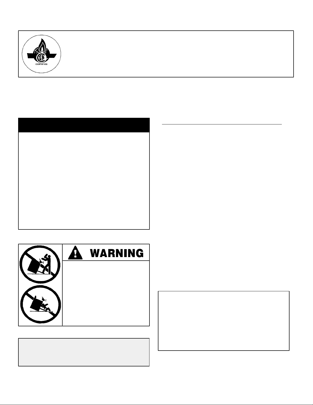
INSTALLER: LEAVE THESE INSTRUCTIONS WITH THE APPLIANCE
INSTALLATION MANUAL
Dual Fuel 30-inch Wide Free-Standing Range
PLEASE KEEP THIS MANUAL FOR FUTURE REFERENCE
THE MANUAL IS INTENDED TO ASSIST IN THE INITIAL INSTALLATION AND ADJUSTMENTS OF THE RANGE.
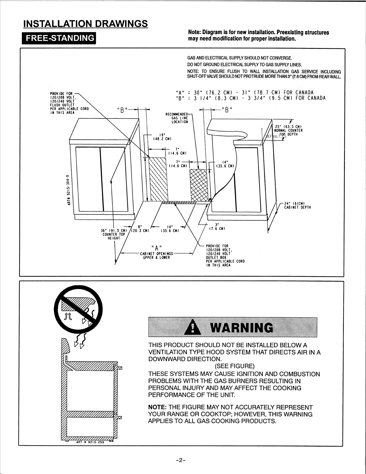
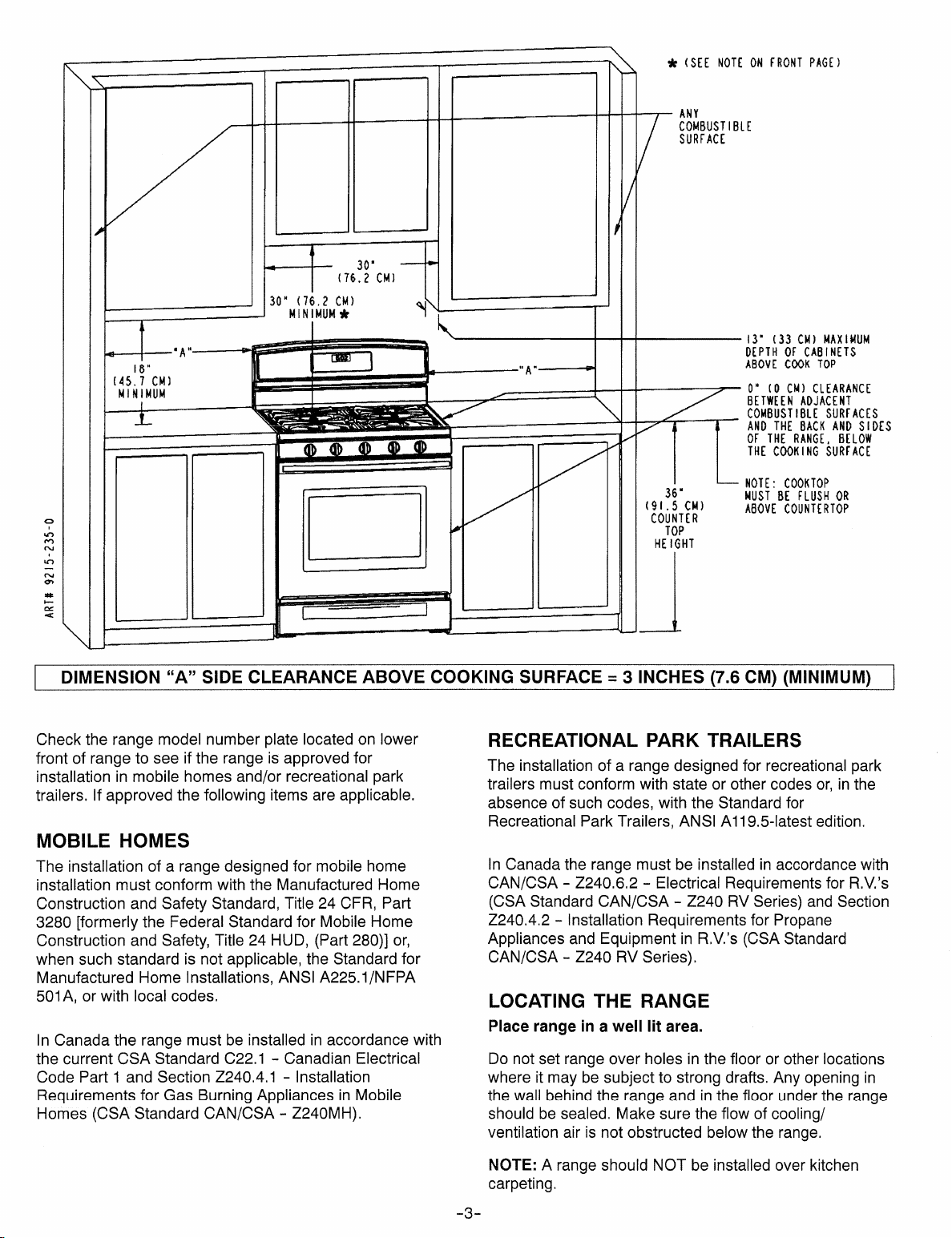
CLEARANCE DIMENSIONS
SPECIAL WARNING
Only qualified personnel should
install or service this range.
Read “Safety Instructions” in the
Use & Care book before using
range.
Range may be installed with zero inches clearance
adjacent to (against) combustible construction at the rear
and on the sides below the cooktop. For complete
information in regard to the installation of wall cabinets
above the range and clearances to combustible wall
above the cooking top see the installation drawings. For
SAFETY CONSIDERATIONS do not install a range in any
combustible cabinetry which is not in accord with the
installation drawings.
Improper installation, adjustment,
alteration, service, maintenance or
use of range can result in serious
injury or property damage.
• ALL RANGES CAN TIP AND
CAUSE INJURIES TO PERSONS.
• INSTALL ANTI-TIP DEVICES
PACKED WITH RANGE.
• FOLLOW ALL INSTALLATION
INSTRUCTIONS.
Your range may not be equipped with
some of the features referred to in this
manual.
* NOTE: The 30 inch (76.2 cm) dimension may be
reduced to not less than 24 inches (61 cm) when the wall
cabinets in a domestic home are protected with fireproof
materials in accordance with American National
Standards -- National Fuel Gas Code or in mobile homes
when they are protected with fireproof materials in
accordance with the Federal Standard for Mobile Home
Construction and Safety.
To eliminate the risk of burns or fire by reaching over
heated surface units, cabinet storage space located
above the surface units should be avoided. If cabinet
storage is to be provided, the risk can be reduced by
installing a range hood that projects horizontally a
minimum of 5 inches (13 cm) beyond the bottom of the
cabinets.
CAUTION: This range has been designed in
accordance with the requirements of various safety
agencies and complies with the maximum allowable
wood cabinet temperatures of 194°F. If this range is
installed with cabinets that have a lower working
temperature than 194°F, discoloration, delamination
or melting may occur. Contact Customer Service
for associated cabinet dimensions and installation
accessories.
8101P729-60
(03-06-00)
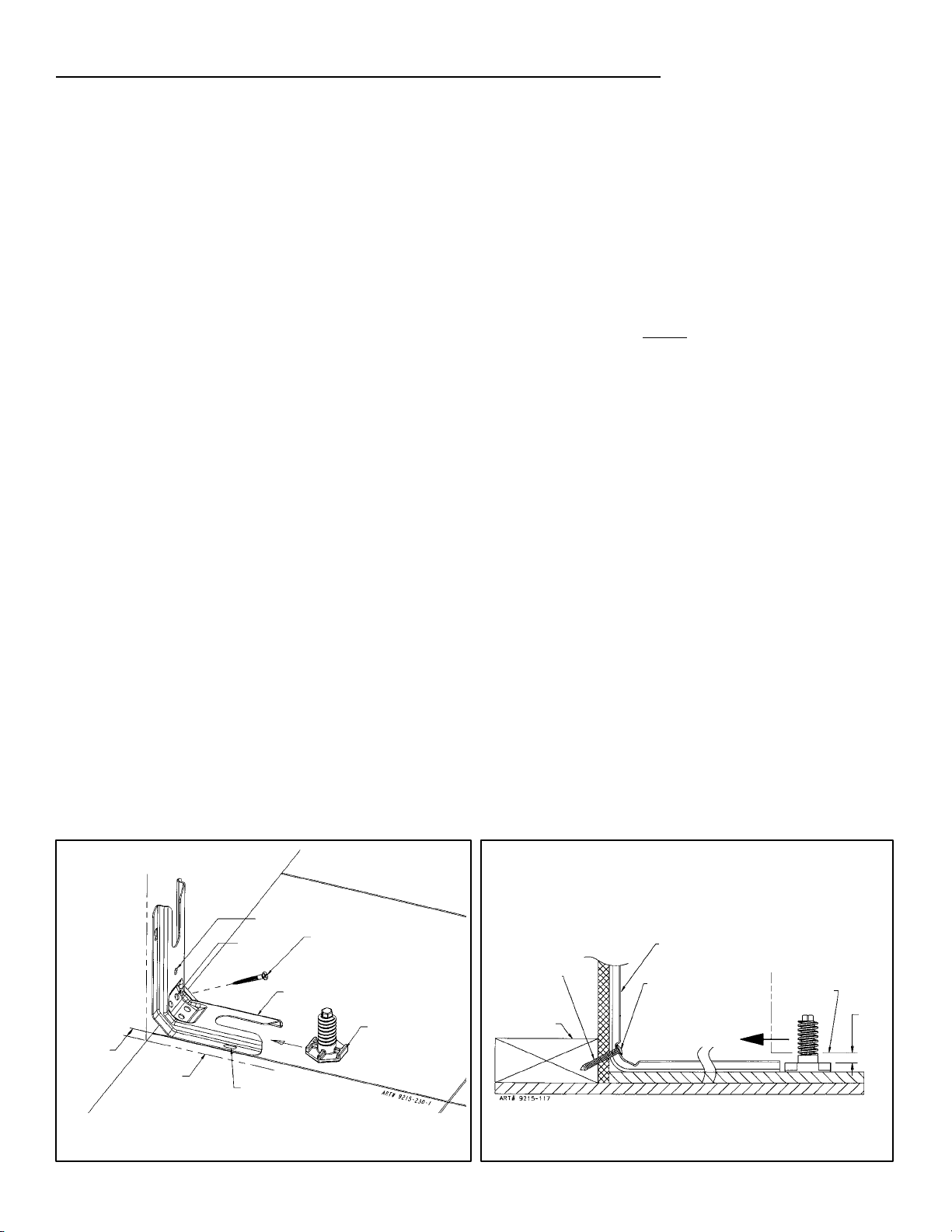
ANTI-TIP DEVICE INSTALLATION INSTRUCTIONS
NOTE: A risk of range tip over exists if the appliance is
not installed in accordance with the installation
instructions provided. The proper use of this device
minimizes the risk of TIP-OVER. In using this device the
consumer must still observe the safety precautions as
stated in the USE and CARE MANUAL and avoid using
the oven door and/or lower drawer as a step stool.
Installation instructions are provided for wood and cement
in either floor or wall. Any other type of construction may
require special installation techniques as deemed
necessary to provide adequate fastening of the ANTI-TIP
bracket to the floor or wall.
STEP 1 -- Locating The Bracket (see figure 1)
A. Determine where either the right or left rear “edge” of
the range will be located and mark the floor or wall.
B. Place the BRACKET 9/16″ (14.5 mm) from the
marked “EDGE” toward center of opening and against
the back wall as shown in figure 1, with orientation
hole against wall.
C. Use the bracket as a template and mark the required
holes, as shown in figure 1 for the type of construction
you will be using.
STEP 2 -- Anti-Tip Bracket Installation
A. Wood Construction:
1. Floor: Locate the center of the two holes identified
in figure 1 as “HOLES FOR FLOOR”. Drill a 1/8″
(3 mm) pilot hole in the center of each hole (a nail
or awl may be used if a drill is not available).
Secure the ANTI-TIP bracket to the floor with the
two screws provided. Proceed to STEP 3.
2. Wall: Locate the center of the two holes identified
in figure 1 as “HOLES FOR WALL. Drill an angled
1/8″ (3 mm) pilot hole in the center of each hole
as shown in figure 2. (A nail or awl may be used if
a drill is not available). Secure the ANTI-TIP
bracket to the wall with the two screws provided
as shown in figure 2. Proceed to STEP 3.
B. Cement or Concrete Construction:
1. Suitable screws for concrete construction can be
obtained at a hardware store. Drill the required
size hole for the screws obtained into the
concrete at the center of the holes identified in
figure 1 as “HOLES FOR FLOOR”. Secure the
ANTI-TIP bracket to the floor. Proceed to STEP 3.
STEP 3 -- Range Installation
A. For safety considerations as well as optimum
performance, adjust the range so it is level and to
desired height prior to installing in cabinet opening.
NOTE: Cooktop MUST
be flush or above
countertop.
Levelness may be checked by placing a spirit level or
a large pan of water on the cooktop or oven rack.
Adjust the range by tipping it forward or back and
rotate the leveling feet as required.
NOTE: A minimum clearance of 1/4″ (6 mm) is
required between the range and the leveling foot that
will engage the anti-tip bracket, (see figure 2).
CAUTION: Damage to the range may occur if range
is moved or lifted by grasping the main top, backguard
or door handles.
B. Align the range to its designated location and prepare
to slide it back into position. Connect gas line and
plug in power cord to outlet following guidelines
outlined in connecting the range and remainder of
installation instructions.
C. Slide range in place visually inspecting to verify that
power cord and gas line are freely routed and
contained within recessed area of back panel.
D. To check the range for proper installation of the
anti-tip bracket, use a flashlight and look underneath
the bottom of the range to see that one of the rear
leveling feet is engaged in the bracket slot.
9/16”
(14.5 mm)
FROM EDGE
OF RANGE
MARKED EDGE
OF RANGE
NOTE: USE A MINIMUM OF (2) SCREWS
TO INSTALL ANTI-TIP BRACKET
TO THE WALL OR FLOOR.
ORIENTATION
HOLE
HOLES FOR
WALL
HOLES FOR
FLOOR
(EACH SIDE)
ATTACH ANTI-TIP BRACKET WITH A
MINIMUM OF TWO (2) LONG SCREWS
TO THE WALL OR FLOOR.
ANTI-TIP
BRACKET
LEVELING
FOOT
SCREWS MUST
ENTER WOOD
OR METAL.
WALL PLATE
ANTI-TIP
BRACKET
SCREW BRACKET
TO WALL
SLIDE IN
TO SECURE
FIGURE 1 FIGURE 2
-- 4 --
RANGE
BOTTOM
1/4”
(6mm)
MIN.
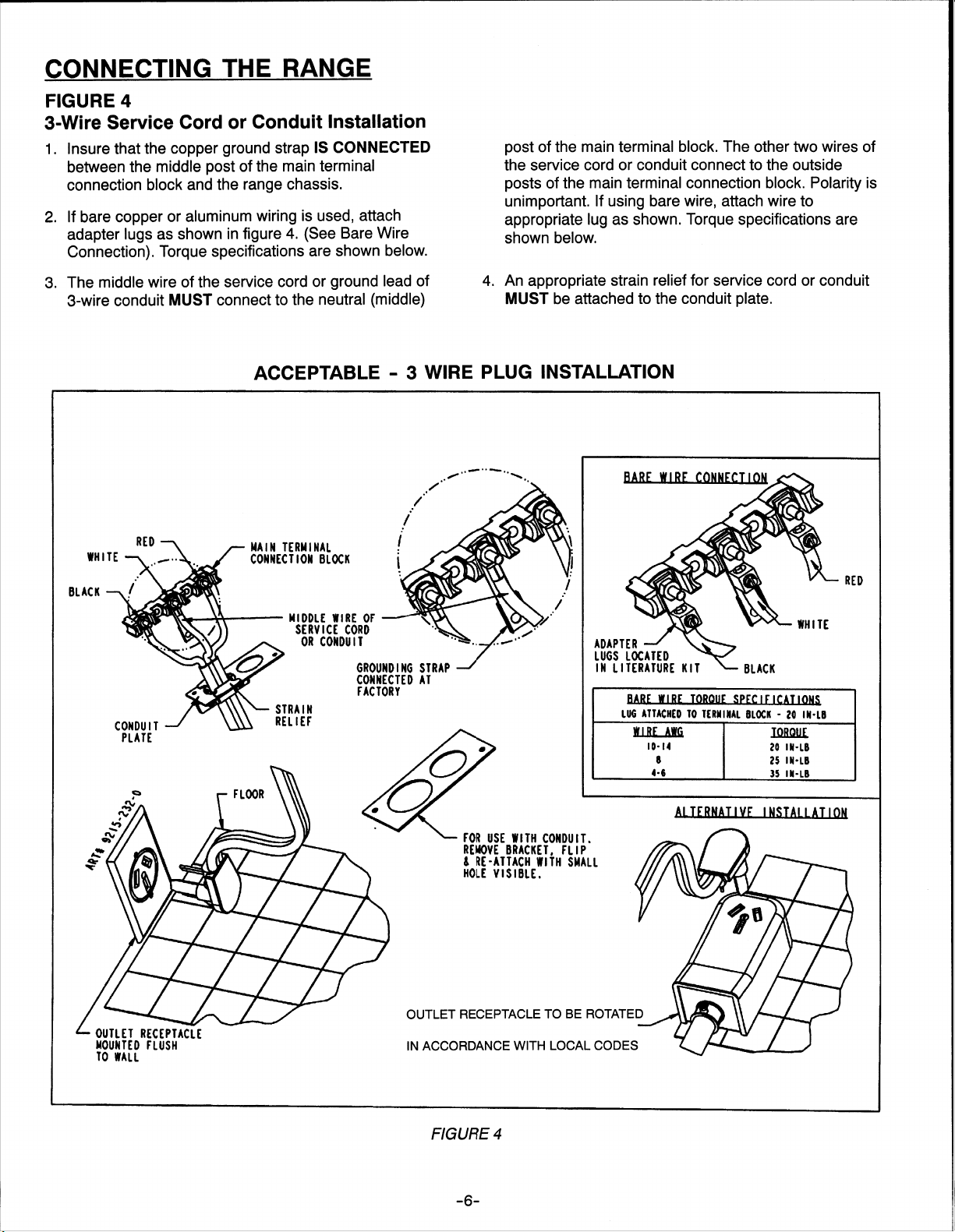
CONNECTING THE RANGE
ELECTRIC SUPPLY
The range must be installed in accordance with Local and
National Electric Code (NEC) ANSI/NFPA No. 70-latest
edition. See rating plate for total connected KW rating.
ELECTRIC SUPPLY (Canada)
The range must be installed in accordance with Local and
Canadian Electric Code CSA STD.C22.1 latest edition.
See rating plate for total connected KW rating.
OUTSIDE WIRING
Your local utility company will tell you whether the present
electric service to your home is adequate. It may be
necessary to increase the size of the wiring to the house
and service switch to take care of the electrical load
demanded by the range. The kilowatt rating for the range
is specified on the rating plate located on front of range.
HOUSE WIRING
Most local Building Regulations and Codes require that all
electrical wiring be done by licensed electricians. All
wiring should conform to Local and National Electrical
Codes. This range requires a single phase three wire
120/240 or a 120/208 volt, 60 Hz, AC circuit. Wiring codes
require a separate circuit be run from the main entrance
panel to the range and that it be equipped with separate
disconnect switch and fuses, either in the main entrance
panel or in a separate switch and fuse box. In some
communities, a solid or flexible continuous armored
conduit must be used from main entrance panel to the
terminal box on the rear of the range. Others will permit
the termination of the range circuit at a polarized three or
four wire plug-in outlet placed at a convenient point near
the back of the range. The range is then connected to this
outlet through an approved range connector (pigtail)
fastened securely to the terminal block with proper strain
relief at the range and a three or four pronged plug at the
opposite end.
by local code. USE COPPER OR ALUMINUM
CONDUCTORS. Main terminal block is recognized for
Copper or Aluminum conductors. If a flexible power cord
is required, it is recommended a cord no longer than 4 ft.
be used. Make connections as explained below and with
reference to the appropriate illustration (see figures 6 and
7). After installation, insure tightness of all electrical
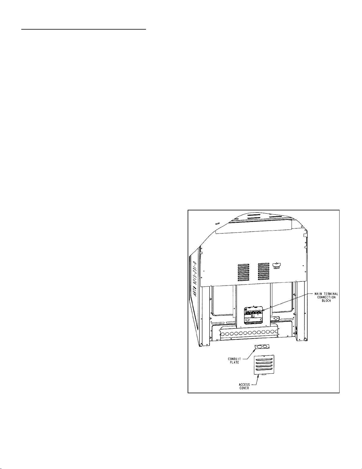
connections and replace all covers.
Remove terminal block access cover from range back.
(See figure 5).
RANGE CONNECTIONS (Canada)
This model was shipped direct from the factory with
service cord (pigtail) attached. There are no range
connections necessary. Just plug into the range outlet.
NOTE: Cord replacement -- ONLY a power supply cord
rated at 240 volts minimum, 40 amperes or 50 amperes
power supply cord that is marked for use with nominal
13/8″ (34.93 mm) diameter connection opening, with
closed loop terminals and marked for use with ranges
shall be used.
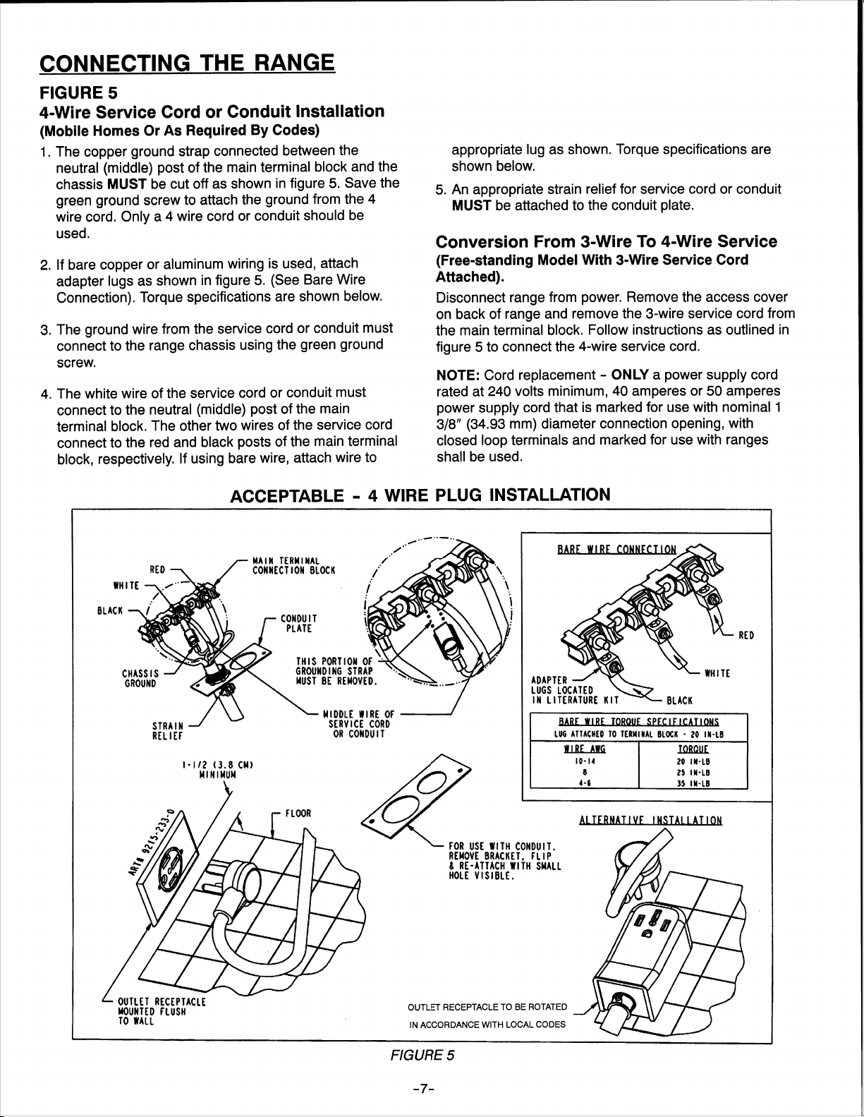
RANGE CONNECTIONS
Some models are shipped direct from the factory with
service cords (pigtails) attached. There are no range
connections necessary on these models. Just plug into
the range outlet. On models not provided with a service
cord, connection to the power supply is necessary.
REMEMBER -- only a 4--conductor cord is to be used on
new branch--circuit installations (1996 NEC), mobile
homes, recreational vehicles, or in an area where local
codes prohibit grounding through the neutral conductor.
Hence, 4--wire service MUST be provided for such
installations. 3--wire service may be used when permitted
FIGURE 3
-- 5 --
CONNECTING THE RANGE
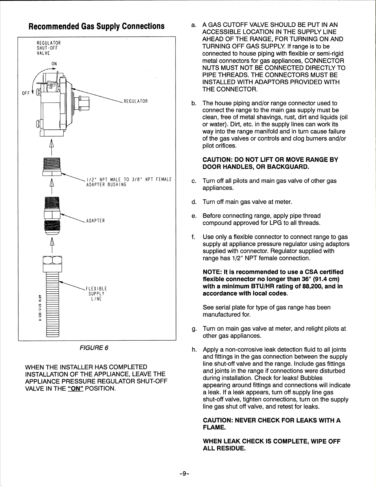
Gas Supply
Installation of this range must conform with local codes or,
in the absence of local codes, with the National Fuel Gas
Code, ANSI Z223.1-latest edition.
In The Commonwealth Of Massachusetts
This product must be installed by a licensed plumber or
gas fitter when installed within the Commonwealth of
Massachusetts.
A “T” handle type manual gas valve must be installed in
the gas supply line to this appliance.
A flexible gas connector, when used, must not exceed a
length of three (3) feet / 36 inches.
In Canada the range must be installed in accordance with
the current CGA Standard CAN/CGA--B149 -- Installation
Codes for Gas Burning Appliances and Equipment and/or
local codes.
Gas leaks may occur in your system and result in a
dangerous situation. Gas leaks may not be detected
by smell alone. Gas suppliers recommend you
purchase and install an UL approved gas detector.
Install and use in accordance with the manufacturer’s
instructions.
excess of 1/2 lbs./sq. in. (3.5 kPa) (13.8 in. water
column).
2. The appliance must be isolated from the gas supply
piping system by closing its individual manual shutoff
valve during any pressure testing of the gas supply
piping system at test pressures equal to or less than
1/2 lbs./sq. in. (3.5 kPa) (13.8 in. water column).
Gas Supply Connection (See figure 3)
A QUALIFIED SERVICEMAN OR GAS APPLIANCE
INSTALLER MUST MAKE THE GAS SUPPLY
CONNECTION. Leak testing of the appliance shall be
conducted by the installer according to the
instructions given in section h.
NATURAL GAS SUPPLY LINE MUST HAVE A NATURAL
GAS SERVICE REGULATOR. INLET PRESSURE TO
THIS APPLIANCE SHOULD BE REDUCED TO A
MAXIMUM OF 14 INCHES WATER COLUMN (0.5
POUNDS PER SQUARE INCH (P.S.I.). LIQUEFIED
PETROLEUM (L.P.)
MUST HAVE A L.P. GAS PRESSURE REGULATOR.
INLET PRESSURE TO THIS APPLIANCE SHOULD BE
REDUCED TO A MAXIMUM OF 14 INCHES WATER
COLUMN (0.5 P.S.I.). INLET PRESSURES IN EXCESS
OF 0.5 P.S.I. CAN DAMAGE THE APPLIANCE
PRESSURE REGULATOR AND OTHER GAS
COMPONENTS IN THIS APPLIANCE AND CAN RESULT
IN A GAS LEAK.
NOTE: This range is shipped from the factory set for
Natural Gas at 4″ water column pressure.
/PROPANE GAS SUPPLY LINE
Checking Pressure Of House Piping
System
1. The appliance and its individual shutoff valve must be
disconnected from the gas supply piping system during
any pressure testing of that system at test pressures in
Gas supply pressure for testing regulator must be at
least 1″ water column pressure above manifold
pressure shown on serial plate.
If conversion to LP Gas is required, convert appliance
before installation.
-- 8 --

RANGE ADJUSTMENTS
Top Section -- Electric Ignition
To operate, push and turn top burner knob to the LITE
position. The top burner will light. To turn OFF spark after
the top burner has ignited, turn knob to HI setting.
NOTE: Top burners are not adjustable.
Air Shutter -- Bake/Broil Burner
NOTE: If oven burner does not ignite, check oven gas
shut-off position at the regulator.
a. The approximate length of the flame of oven burner is
a 1/2 inch distinct inner blue flame, figure 7.
GAS CONVERSION
SEE INSTRUCTIONS FOR GAS CONVERSION
LOCATED ON THE BACK OF THE RANGE.
FIGURE 7
b. Bake/broil burner flame can be checked as follows:
1. Yellow flame on burner -- open burner air shutter
to the widest opening that will not cause the flame
to lift or blow off the burner when cold. (See #2 on
figure 8). Some yellow tipping on LP is normal.
2. Distinct blue flame but lifting -- close burner air
shutter to the point where it will not cause the
flame to lift or blow off the burner when cold. (See
#2 on figure 8).
FIGURE 8
-- 1 0 --

INSTALADOR: DEJE ESTAS INSTRUCCIONES CON EL ELECTRODOMÉSTICO
MANUAL DE INSTALACIÓN
Combustible dual independiente convencional de
76 cm (30 pulgadas) de ancho
CONSERVE ESTE MANUAL COMO REFERENCIA FUTURA
EL MANUAL TIENE LA FINALIDAD DE AYUDARLE EN LA INSTALACIÓN Y LOS AJUSTES INICIALES
DE LA ESTUFA.
ADVERTENCIA ESPECIAL
Solamente el personal calificado
deberá instalar o dar servicio a esta
estufa.
Lea las “Instrucciones de
seguridad” en el libro de Uso y
cuidado antes de usar la estufa.
La instalación, los ajustes, el
servicio, el mantenimiento o el uso
incorrectos, así como las
alteraciones de la estufa pueden
causar lesiones graves o daños
materiales.
DIMENSIONES DEL ESPACIO
LIBRE
La estufa puede instalarse con un espacio libre de cero
centímetros adyacente (contra) a la construcción
combustible en la parte posterior y en los lados debajo de
la superficie para cocinar. Para obtener la información
completa relacionada con la instalación de gabinetes de
pared encima de la estufa y los espacios libres a las
paredes combustibles por encima de la parte superior de
la superficie para cocinar, vea los dibujos de instalación.
Por MOTIVOS DE SEGURIDAD no instale la estufa en
ningún gabinete combustible que no esté de acuerdo con
los dibujos de instalación.
* NOTA: La dimensión de 76.2 cm (30”) no puede redu--
cirse a menos de 61 cm (24”) cuando los gabinetes de
pared en una casa están protegidos con materiales contra
incendios de acuerdo con las Normas Nacionales Esta-dounidenses – el Código Nacional de Gas Combustible o
en casas móviles cuando están protegidas con materiales
contra incendios de acuerdo con la Norma Federal para
Construcción y Seguridad de Casas Móviles.
ADVERTENCIA
• TODAS LAS ESTUFAS PUEDEN
VOLTEARSE Y CAUSAR
LESIONES A LAS PERSONAS.
• INSTALE LOS DISPOSITIVOS
ESTABILIZADORES EMPACADOS CON LA ESTUFA.
• SIGA TODAS LAS INSTRUCCIONES DE INSTALACIÓN.
Su estufa podría no estar equipada
con algunas de las características
mencionadas en este manual.
Para eliminar el riesgo de quemaduras o incendios al
atravesarse por encima de las unidades calientes de la
superficie, debe evitarse el almacenaje en los gabinetes
por encima de las unidades de la superficie. Si se va a
proporcionar almacenaje, puede reducirse el riesgo
instalando una campana de estufa que sobresalga
horizontalmente cuando menos 12.7 cm (5”) más que los
gabinetes inferiores.
PRECAUCIÓN: Esta estufa ha sido diseñada de
acuerdo con los requisitos de varias agencias de
seguridad y cumple con las temperaturas máximas
permitidas para los gabinetes de madera de 90°C
(194°F). Si esta estufa se instala en gabinetes que
tienen una tolerancia más baja a las temperaturas,
podría ocurrir decoloración, pérdida del laminado o
derretimiento. Póngase en contacto con el servicio
de atención al cliente para obtener las dimensiones
del gabinete asociado y los accesorios de
instalación.


INSTRUCCIONES DE INSTALACIÓN DEL DISPOSITIVO ESTABILIZADOR
NOTA: Existe el riesgo de que la estufa se voltee si el
electrodoméstico no se instala de acuerdo con las
instrucciones de instalación provistas. El uso correcto de
este dispositivo reduce el riesgo de VOLTEO. Cuando se
use este dispositivo el propietario debe aún observar las
precauciones de seguridad según se indican en el
MANUAL DE USO Y CUIDADO y evitar usar la puerta del
horno o el cajón inferior como banquillo.
Se proporcionan las instrucciones para madera y
cemento tanto para piso como para pared. Cualquier otro
tipo de construcción podría requerir técnicas de
instalación especiales según se determine necesario para
proporcionar un anclaje adecuado del soporte
ESTABILIZADORalpisooalapared.
PASO 1 – Ubicación del soporte (vea la figura 1)
C. Determine la ubicación del “borde” derecho o
izquierdo de la estufa y marque el piso o la pared.
D. Coloque el SOPORTE a 2.4 cm (9/16”) del “BORDE”
marcado hacia el centro del hueco y contra la pared
posterior, según se muestra en la figura 1, con el
orificio de orientación contra la pared.
E. Use el soporte como plantilla y marque los orificios
necesarios, según se muestra en la figura 1, para el
tipo de construcción que usará.
PASO 2 – Instalación del soporte estabilizador
I. Construcción de madera:
1. Piso: Ubique el centro de los dos orificios que se
identifican en la figura 1 como “ORIFICIOS PARA
EL PISO”. Taladre un orificio piloto con una broca
de 3 mm (1/8”) en el centro de cada orificio
(puede usar un clavo o un punzón si no tiene un
taladro disponible). Asegure el soporte
ESTABILIZADOR al piso con los dos tornillos
provistos. Continúe con el paso 3.
2. Pared: Ubique el centro de los dos orificios que
se identifican en la figura 1 como “ORIFICIOS
PARA LA PARED”. Taladre un orificio piloto en
ángulo con una broca de 3 mm (1/8”) en el centro
de cada orificio como se muestra en la figura 2.
(Puede usar un clavo o un punzón si no tiene
disponible un taladro.) Asegure el soporte
ESTABILIZADOR a la pared con los dos tornillos
provistos según se muestra en la figura 2.
Continúe con el PASO 3.
J. Construcción de cemento o concreto:
1. Puede obtenerse tornillos apropiados para la
construcción de concreto en una ferretería. Con
el taladro haga el orificio del tamaño requerido
para el tipo de tornillos que haya obtenido, en el
concreto, en el centro de los orificios identificados
en la figura 1 como “ORIFICIOS PARA EL PISO”.
Asegure el soporte ESTABILIZADOR al piso.
Continúe con el paso 3.
PASO 3 – Instalación de la estufa
A. Por motivos de seguridad así como para obtener el
desempeño óptimo, ajuste la estufa de manera que
esté bien nivelada y a la altura deseada antes de
instalarla en el hueco del gabinete.
NOTA: La superficie para cocinar DEBE
estar al
ras o por encima del mostrador.
La nivelación puede revisarse colocando un nivel de
burbuja de aire o un recipiente grande con agua en la
superficie para cocinar o en la parrilla del horno.
Ajuste la estufa ladeándola hacia delante o hacia
atrás y girando la pata niveladora según sea
necesario.
NOTA: Se requiere un espacio libre de cuando
menos 6 mm (1/4”) entre la estufa y la pata niveladora
que se enganchará al soporte estabilizador, vea la
figura 2.
PRECAUCIÓN: La estufa puede dañarse si se mueve
o levanta tomándola por la parte superior principal o
por el protector posterior o por las asas de la puertas.
B. Alinee la estufa en su ubicación final y prepárela para
deslizarla hacia atrás en su lugar. Conecte la tubería
de gas y enchufe el cordón eléctrico a un tomaco-rrinte siguiendo las normas indicadas en la conexión y
el resto de las instrucciones de instalación.
C. Deslice la estufa en su lugar inspeccionando visual--
mente para comprobar que el cordón eléctrico y la
tubería de gas estén libremente colocadas y conteni-das dentro del área ahuecada del panel posterior.
D. Para revisar que el soporte estabilizador de la estufa
esté bien instalado, use una linterna y vea por debajo
de la estufa para comprobar que una de las patas
niveladoras esté enganchada en la hendidura del
soporte.
NOTA: USE CUANDO MENOS DOS (2)
TORNILLOS PARA INSTALAR EL
SOPORTE ESTABILIZADOR A LA
PARED O AL PISO.
14.5 MM
(9/16”)
DEL
BORDE DE
LA ESTUFA
BORDE
MARCADO DE
LA ESTUFA
ORIFICIO DE
ORIENTACIÓN
ORIFICIOS
PARA LA
PARED
ORIFICIOS PARA
EL PISO (EN
CADA LADO)
SUJETE EL SOPORTE ESTABILIZADOR
CON UN MÍNIMO DE DOS (2) TORNILLOS
LARGOSALAPAREDOALPISO.
SOPORTE
ESTABILIZADOR
PATA
NIVELADORA
LOS
TORNILLOS
DEBEN
PENETRAR EN
LA MADERA O
EL METAL.
PLACA DE
PARED
SOPORTE
ESTABILIZADOR
ATORNILLE EL
SOPORTE A LA PARED
DESLICE PARA
ASEGURAR
FIGURA 1 FIGURA 2
-- 4 --
FONDO
DEL
HORNO
6MM
(1/4”)
MÍN.

CONEXIÓN DE LA ESTUFA
SUMINISTRO ELÉCTRICO
La estufa debe instalarse de acuerdo a los Códigos
Eléctricos Locales y Nacionales (NEC) ANSI/NFPA No.
70--última edición. Vea la placa de clasificación para
obtener la clasificación total de KW conectados.
SUMINISTRO ELÉCTRICO (Canadá)
La estufa debe instalarse de acuerdo a los Códigos
Eléctricos Canadienses y Locales CSA STD.C22.1 última
edición. Vea la placa de clasificación para obtener la
clasificación total de KW conectados.
CABLEADO EXTERIOR
La compañía local de servicios públicos le informará si es
adecuado el servicio eléctrico actual a su casa. Podría
ser necesario aumentar el tamaño del cableado a la casa
y el interruptor de servicio para poder con la carga
eléctrica que la estufa demanda. La clasificación de
kilovatios para la estufa está especificada en la placa de
clasificación que se ubica al frente de la estufa.
CABLEADO DE LA CASA
La mayoría de los Códigos y Reglamentos locales para
edificios exigen que todo el cableado eléctrico lo instale
un electricista con licencia. Todo el cableado debe estar
en conformidad con los Códigos Eléctricos Nacionales y
Locales. Esta estufa requiere un circuito de CA
monofásico de tres o cuatro cables de 120/240 o de
120/208 voltios, 60 Hz. Los códigos de cableado
requieren que se tenga un circuito separado del tablero
principal de entrada a la estufa y que esté equipado con
fusibles y con un interruptor de desconexión, ya sea en el
tablero principal de entrada o en un interruptor y caja de
fusibles separados. En algunas comunidades, debe
usarse un conductor flexible o sólido acorazado continuo
del tablero principal de entrada a la caja terminal en la
parte posterior de la estufa. Otros permitirán que el
circuito de la estufa termine en un tomacorriente de
conexión polarizada de tres o cuatro cables colocado en
un lugar conveniente cerca de la parte posterior de la
estufa. Entonces se puede conectar la estufa a este
tomacorriente mediante un conector de la clasificación
aprobada (cable flexible de conexión) asegurado con
firmeza al bloque terminal, con el protector contra tirones
apropiado, a la estufa y a un enchufe de tres o cuatro
puntas en el otro extremo.
mediante el conductor neutro. Por lo tanto, DEBE
proveerse un servicio de 4 alambres en dichas
instalaciones. El servicio de 3 alambres puede usarse
cuando lo permitan los códigos locales. USE
CONDUCTORES DE COBRE O ALUMINIO. El bloque
terminal principal está indicado para uso con conductores
de cobre o aluminio. Si se necesita un cordón de
suministro eléctrico, se recomienda usar un cordón que
no sea más largo de 4 pies. Haga las conexiones según
se explica a continuación y consulte las ilustraciones
correspondientes (vea las figuras 6 y 7). Después de la
instalación, asegúrese de que todas las conexiones
eléctricas estén bien ajustadas y coloque todas las
cubiertas.
Quite la cubierta de acceso del bloque terminal de la parte
posterior de la estufa. (Vea la figura 5).
CONEXIONES DE LA ESTUFA (en Canadá)
Este modelo se embarcó directamente de fábrica con el
cordón de servicio (cable flexible de conexión). No es
necesario hacer ninguna conexión en la estufa.
Sencillamente conéctela en el tomacorriente de la estufa.
NOTA: Reemplazo del cordón, SOLAMENTE se deberá
utilizar un cordón de suministro eléctrico de clasificación
mínima de 240 voltios, 40 ó 50 amperios que esté
marcado para usarse con una abertura nominal de
conexión de 1 3/8″ (34.93 mm) de diámetro, con
terminales de lazo cerrado y que estén marcados para
utilizarse con estufas.
BLOQUE DE
CONEXIÓN
DEL
TERMINAL
PRINCIPAL
CONEXIONES DE LA ESTUFA
Algunos modelos se envían directamente de fábrica con
los cordones de servicio (cables flexibles de conexión)
sujetos. No es necesario hacer ninguna conexión en
estos modelos de estufa. Sencillamente conéctelos en el
tomacorriente de la estufa. En los modelos que no vienen
con el cordón de servicio, es necesario hacer la conexión
al suministro de energía. RECUERDE -- solamente debe
usarse un cordón de 4 conductores en las instalaciones
nuevas de circuitos derivados (1996 NEC), áreas en
donde los códigos locales prohiben la conexión a tierra
PLACA CONDUCTORA
CUBIERTA DE ACCESO
FIGURÀ 3
-- 5 --


CONEXIÓN DE LA ESTUFA
FIGURA 5
INSTALACIÓN DEL CORDÓN DE SERVICIO DE 4
CABLES O DEL CONDUCTOR
(COMO LO REQUIEREN LAS CASAS MÓVILES O LOS
CÓDIGOS LOCALES)
1. La tira de conexión a tierra de cobre que está
conectada entre el poste neutro (medio) del bloque del
terminal principal y el bastidor DEBE cortarse según se
muestra en la figura 5. Conserve el tornillo verde de
conexión a tierra para sujetar la tierra del cordón de 4
cables. Solamente debe utilizarse un cordón de 4
cables o conductor.
2. Si se usa alambrado desnudo de cobre o aluminio,
sujete la lengüeta de conexión del adaptador según se
muestra en la figura 5. (Vea Conexión de alambre
desnudo). Las especificaciones de torsión se muestran
a continuación.
3. El cable de conexión a tierra del cordón de servicio o
del conductor debe conectarse al bastidor de la estufa
usando el tornillo verde de conexión a tierra.
4. El cable blanco del cordón de servicio o del conductor
debe conectarse al poste neutro (medio) del bloque del
terminal principal. Los otros dos cables del cordón de
servicio o del conductor se conectan a los postes rojo y
negro del bloque del terminal principal, respectivamente. Si va a usar alambre desnudo, sujete el
alambre a la lengüeta de conexión correspondiente
según se muestra. Las especificaciones de torsión se
muestran a continuación.
5. Debe colocarse a la placa del conductor un protector
contra tirones apropiado en el cordón de servicio o el
conductor.
CONVERSIÓN DE SERVICIO DE 3 CABLES A 4
CABLES
(Modelo individual con cordón sujeto de servicio de 3
cables)
Desconecte la estufa de la energía eléctrica. Quite la
cubierta de acceso en la parte posterior de la estufa y
quite el cordón de servicio de 3 cables del bloque del
terminal principal. Siga las instrucciones a continuación
según se indica en la figura 5 para conectar el cordón de
servicio de 4 cables.
NOTA: Reemplazo del cordón, deberá utilizarse
SOLAMENTE un cordón de suministro de energía con
clasificación mínima de 240 voltios, 40 ó 50 amperios que
esté marcado para utilización con aberturas nominales de
13/8″ (34.93 mm) de diámetro, con terminales de lazo
cerrado y marcados para utilización con estufas.
ROJO
BLANCO
NEGRO
CONEXIÓN A
TIERRA DEL
CHASIS
PROTECCIÓN
CONTRA TIRONES
INSTALACIÓN ACEPTADA DE UNA CLAVIJA DE CUATRO CABLES
BLOQUE DE CONEXIÓN
DEL TERMINAL
PRINCIPAL
PLACA DEL
CONDUCTOR
DEBE QUITARSE
ESTA PORCIÓN
DE LA CORREA
DE TIERRA.
ALAMBRE EN
MEDIO DEL
CORDÓN DE
SERVICIO O DEL
CONDUCTOR
1--1/2″ (3.8 CM) MÍNIMO
PISO
PARA EL USO CON
CONDUCTOR. QUITE EL
SOPORTE, VOLTÉELO Y
VUELVA A SUJETARLO
CON EL ORIFICIO
PEQUEÑO A LA VISTA.
CONEXIÓN DE
ALAMBRE
LENGÜETAS DE CONEXIÓN
DEL ADAPTADOR UBICADAS
EN EL PAQUETE DE MATERIALES IMPRESOS
ESPECIFICACIONESDE TORSIÓN DEL ALAMBRE DESNUDO
LENGÜETA DE CONEXIÓN SUJETA AL BLOQUE TERMINAL -- 20 PULG/LIBRAS
CALIBRE DEL ALAMBRE
DESNUDO
ROJO
BLANCO
NEGRO
DE
TORSIÓN
10--14
8
4--6
20 PULG/LIBRAS
25 PULG/LIBRAS
35 PULG/LIBRAS
INSTALACIÓN ALTERNATIVA
RECEPTÁCULO DEL
TOMACORRIENTE
MONTADO AL RAS
DE LA PARED
RECEPTÁCULO DEL
TOMACORRIENTE A
ROTARSE SEGÚN SE
MUESTRA SI NO ESTÁ AL
RASDELAPARED
FIGURA 5
-- 7 --

CONEXIÓN DE LA ESTUFA
Suministro de gas
La instalación de esta estufa debe estar en conformidad
con los códigos locales o, si no existieran, con la última
edición del Código Nacional de Gas Combustible, ANSI
Z223.1
En el estado de Massachusetts
Este producto debe instalarlo un plomero certificado o
un ajustador de gas cuando se instale dentro del estado
de Massachusetts.
Debe instalarse una válvula manual con asa tipo “T” en
la tubería de suministro de gas al electrodoméstico.
Los conectores flexibles de gas, cuando se usen, no
deben sobrepasar una longitud de 91.44 cm (36 pulg).
En Canadá la estufa debe instalarse de acuerdo con la
Norma actual CAN/CGA--B149 de CGA – Códigos de
instalación para electrodomésticos y equipos que queman
gas y con los códigos locales.
ADVERTENCIA
Podrían ocurrir fugas de gas en el sistema y causar
una situación peligrosa. Las fugas de gas podrían no
detectarse sólo por el olor. Los proveedores de gas
recomiendan que compre e instale un detector de
gas aprobado por UL. Instale y use de acuerdo con
las instrucciones del fabricante.
2. El electrodoméstico debe estar aislado del sistema de
suministro de gas cerrando la válvula de cierre
individual durante las pruebas de presión de ese
sistema a presiones iguales o menores de 3.5 kPa (1/2
libra por pulgada cuadrada) (35 cm (13.8 pulgadas) de
columna de agua).
Conexión del suministro de gas (vea la figura 3)
LA CONEXIÓN DE GAS DEBE REALIZARLA UN
TÉCNICO CALIFICADO DE SERVICIO O UN
INSTALADOR DE ELECTRODOMÉSTICOS DE GAS.
Las pruebas de fugas del electrodoméstico debe
realizarlas el instalador de acuerdo con las
instrucciones indicadas en la sección h.
LA TUBERÍA DE SUMINISTRO DE GAS DEBE TENER
UN REGULADOR DE SERVICIO DE GAS NATURAL. LA
PRESIÓN DE ENTRADA A ESTE
ELECTRODOMÉSTICO DEBE REDUCIRSE A UN
MÁXIMO DE 35.5 cm (14 PULGADAS) DE COLUMNA
DE AGUA (0.5 LIBRAS POR PULG CUADRADA (PSI).
LA TUBERÍA DE SUMINISTRO DE GAS
PROPANO/PETRÓLEO LÍQUIDO (LP) DEBE TENER UN
REGULADOR DE PRESIÓN DE GAS LP. LA PRESIÓN
DE ENTRADA A ESTE ELECTRODOMÉSTICO DEBE
REDUCIRSE A UN MÁXIMO DE 35.5 cm
(14 PULGADAS) DE COLUMNA DE AGUA (0.5 PSI).
LAS PRESIONES DE ENTRADA SUPERIORES A 0.5
PSI PUEDEN DAÑAR EL REGULADOR DE PRESIÓN Y
OTROS COMPONENTES DE GAS DEL
ELECTRODOMÉSTICO Y PROVOCAR FUGAS DE GAS.
NOTA: Esta estufa se embarca de fábrica lista para
usarse con gas natural a una presión de 10.16 cm (4”) de
columna de agua.
Para revisar la presión del sistema
de presión de la casa
1. El electrodoméstico y su válvula de cierre individual
deben estar desconectados del sistema de suministro
de gas durante las pruebas de presión de ese sistema
a presiones que sobrepasen 3.5 kPa (1/2 libra por
pulgada cuadrada) (35 cm (13.8 pulgadas) de columna
de agua).
La presión del suministro de gas para probar el
regulador debe ser de cuando menos 2.54 cm (1”) de
presión de columna de agua por encima de la presión
del múltiple que se indica en la placa de datos.
Si se necesita la conversión a gas LP, convierta el
electrodoméstico antes de iniciar la instalación.
-- 8 --


AJUSTES DE LA ESTUFA
Sección superior – Encendido electrónico
Para que funcione, empuje y gire la perilla del quemador
superior a la posición de encender “LITE”. El quemador
superior se encenderá. Para APAGAR la chispa después
de que se haya encendido el quemador superior, gire la
perilla al ajuste alto “HI”.
NOTA: Los quemadores superiores no se ajustan.
Obturador de aire – Quemador de
horneado/asado
NOTA: Si no se enciende el quemador, revise la posición
de la válvula de cierre del gas del horno en el regulador.
a. La longitud aproximada de la llama del quemador del
horno es una llama cónica con el interior azul, bien
definida de 1.27 cm ( 1/2”), figura 7.
CONVERSIÓN DE GAS
CONSULTE LAS INSTRUCCIONES PARA LA
CONVERSIÓN DE GAS QUE SE ENCUENTRA
EN LA PARTE POSTERIOR DE LA ESTUFA.
FIGURA 7
LLAMA CON CONO INTERNO
DE 1.27 CM (1/2”)
b. La llama del quemador de horneado/asado puede
revisarse de la manera siguiente:
2. Llama amarilla en el quemador – abra el
obturador de aire del quemador a la posición más
abierta que no cause que se apague ni levante la
llama cuando el quemador esté frío. (Vea el
número 2 de la figura 8.) Las puntas algo
amarillentas en el gas LP son normales.
3. Llama azul bien definida pero se levanta -- cierre
el obturador de aire hasta el punto en donde no
cause que se levante o apague la llama cuando
el quemador esté frío. (Vea el número 2 de la
figura 8.)
OBTURADOR DE AIRE
CAMPANA DE ORIFICIO
FIGURA 8
TORNILLO DE SEGURIDAD
-- 1 0 --

INSTALLATEUR: VEUILLEZ LAISSER CES INSTRUCTIONS AVEC L’APPAREIL
MANUEL DE MISE EN SERVICE
Cuisinière autonome à DEUX ÉNERGIES de 76,2 cm
(30 po)
VEUILLEZ CONSERVER CE MANUEL POUR RÉFÉRENCE
ULTÉRIEURE
CE MANUEL EST DESTINÉ À FACILITER LA MISE EN SERVICE ET LE RÉGLAGE INITIAUX DE LA CUISINIÈRE.
DÉGAGEMENT NÉCESSAIRE
AVERTISSEMENT SPÉCIAL
La mise en service et le dépannage de
cette cuisinière doivent être réalisés
uniquement par du personnel qualifié.
Lire les « Mesures de sécurité » dans
le manuel de l’utilisateur avant de
l’utiliser.
Une mauvaise réalisation de la mise
en place, du réglage, de toutes
modifications ou réparations ou de
l’entretien de la cuisinière ou son
usage incorrect peuvent entraîner
des blessures ou des dégâts graves.
La cuisinière peut avoir un dégagement nul (0 po/cm) par
rapport aux parois en matériaux combustibles à l’arrière et
sur les côtés au--dessous de la surface de cuisson (elle
peut être contre ces parois). Pour tous renseignements
concernant la pose d’armoires murales au--dessus de la
cuisinière et des dégagements à respecter par rapport
aux parois combustibles se trouvant au--dessus de la
surface de cuisson, se reporter aux schémas
d’installation. Pour des RAISONS DE SÉCURITÉ, ne pas
monter la cuisinière dans une armoire en matériau
combustible non conforme aux schémas d’installation.
*REMARQUE : La dimension de 76,2 cm (30 po) peut
être réduite à 61 cm (24 po) si les armoires murales d’un
logement sont pro-tégées par des matériaux ininflammables conformément
aux normes American National Standards -- National Fuel
Gaz Code ou, dans le cas de maisons mobiles, si les
armoires murales sont protégées par des matériaux
ininflammables conformément aux règlements du Federal
Standard for Mobile Home Construction and Safety.
AVERTISSEMENT
• TOUTES LES CUISINIÈRES
PEUVENT BASCULER ET
PROVOQUER DES BLESSURES.
• POSER LES DISPOSITIFS DE
STABILISATION FOURNIS AVEC
CETTE CUISINIÈRE.
• SUIVRE TOUTES LES CON -SIGNES DE MISE EN SERVICE.
Votre cuisinière peut ne pas être dotée
de toutes les fonctions mentionnées
dans ce manuel.
Pour éliminer tout risque de brûlure ou d’incendie en
essayant d’atteindre un objet placé au--dessus d’éléments
brûlants, éviter d’avoir un espace de rangement
au--dessus de la surface de cuisson. S’il doit y avoir une
armoire au--dessus de la table de cuisson, l’installation
d’une hotte dépassant d’au moins 13 cm (5 po) de sa
partie inférieure réduira les risques liés à ce type
d’entreposage.
ATTENTION : Cette cuisinière satisfait aux règles
de divers organismes de protection et aux normes
relatives à la température maximum permise de
90 ° C (194 ° F) pour les armoires en bois. Si cette
cuisinière est adjacente à des armoires pouvant
supporter une température inférieure à 90 ° C
(194 °5 F) seulement, celles--ci peuvent se
décolorer, se délaminer ou fondre. Prenez contact
avec le service à la clientèle pour obtenir les
dimensions de l’armoire et les accessoires
d’installation.


ANTI-MISE EN PLACE DU SUPPORT DE STABILISATION
REMARQUE : La cuisinière risque de basculer si elle
n’est pas mise en place conformément aux instructions
fournies. Si le dispositif de stabilisation est utilisé
correctement, il réduit le risque que la cuisinière ne BASCULE. Même si le dispositif est utilisé correctement,
le consommateur doit observer les précautions indiquées
dans le MANUEL D’UTILISATION ET D’ENTRETIEN et
éviter d’utiliser la porte du four et/ou le tiroir inférieur
comme un tabouret.
Les instructions sont prévues pour un plancher ou un mur
en bois ou en ciment. Un autre matériau pourra requérir
des techniques spéciales, qu’il conviendra de déterminer,
pour assurer la fixation d u SUPPORT DE STABILISATION
au mur ou au plancher.
ÉTAPE 1 -- Emplacement du support (voir figure 1)
A. Déterminer où le « bord » gauche ou droit de la
cuisinière se trouvera une fois celle--ci en place et le
marquer d’un repère sur le plancher.
B. Placer le SUPPORT à 14 mm (9/16 po) de la marque
« BORD » en allant vers le centre de l’ouverture et
contre le mur arrière tel qu’indiqué à la figure 1, le trou
d’orientation étant contre le mur.
C. Utiliser le support comme gabarit et marquer
l’emplacement de tous les trous pour le type de
matériau sur lequel le support doit être fixé, tel
qu’indiqué à la figure 1.
ÉTAPE 2 -- Pose du support de stabilisation
A. Bois :
1. Plancher : Déterminer le centre des deux trous
identifiés par « TROUS POUR PLANCHER » à la
figure 1. Percer un trou de positionnement de
3 mm (1/8 po) au centre de chaque trou (un clou
ou un poinçon peut également être utilisé si une
perceuse n’est pas disponible). Fixer le support
de STABILISATION au plancher à l’aide des deux
vis fournies. Passer à l’ÉTAPE 3.
2. Mur : Déterminer le centre des deux trous
identifiés par « TROUS POUR MUR » à la figure
1. Percer un trou de positionnement de 3 mm
(1/8 po) au centre de chaque trou (un clou ou un
poinçon peut également être utilisé si une
perceuse n’est pas disponible) tel qu’indiqué à la
figure 2. Fixer le support de STABILISATION au
mur à l’aide des deux vis fournies tel qu’indiqué à
la figure 2. Passer à l’ÉTAPE 3.
B. Ciment ou béton :
1. On trouve des vis convenant au ciment ou au
béton dans les quincailleries. Percer les trous de
positionnement de la grandeur correspondant à
celle des vis obtenues en quincaillerie au centre
des trous identifiés « TROUS POUR PLAN-CHER » à la figure 1. Fixer le support de STABI-LISATION au plancher. Passer à l’ÉTAPE 3.
ÉTAPE 3 -- Mise en place de la cuisinière
A. Pour des raisons de sécurité et pour obtenir des
résultats optimums à la cuisson, régler la cuisinière de
façon à ce qu’elle soit de niveau et à la hauteur
voulue avant de la mettre en place dans l’ouverture.
REMARQUE : La surface de cuisson DOIT
être au
même niveau que le comptoir ou légèrement plus
haute.
Pour vérifier le niveau, mettre un niveau à bulle ou
une grande casserole d’eau sur la surface de cuisson
ou sur la grille du four. Régler le niveau en la
basculant vers l’avant ou l’arrière et en tournant les
pieds de mise à niveau autant que nécessaire.
REMARQUE : Un dégagement minimum de 6 mm
(1/4 po) est exigé entre la cuisinière et le pied de mise
à niveau qui va s’insérer dans le support de
stabilisation (voir figure 2).
ATTENTION : La cuisinière peut être abîmée si elle
est déplacée et soulevée par le dessus, à l’aide du
dosseret ou par les poignées de porte.
B. Placer la cuisinière de façon à ce qu’elle puisse entrer
dans l’ouverture où elle sera encastrée et se préparer à
la pousser en place. Raccorder au gaz et brancher le
cordon d’alimentation dans la prise en suivant les
indications fournies pour le raccordement de la cuisinière
et dans le reste des consignes de mise en service.
C. Glisser la cuisinière en place en l’inspectant
visuellement pour s’assurer que le cordon
d’alimentation et la conduite de gaz ne se trouvent
pas coincés et qu’ils s’insèrent dans la partie en creux
du panneau arrière.
D. Pour vérifier si le support de stabilisation est
correctement en place, regarder sous la cuisinière et
s’assurer qu’un des pieds arrière est bien inséré dans
la fente du support.
REMARQUE: UTILISER UN MINIMUM DE DEUX
(2) VIS POUR FIXER LE SUPPORT
AU MUR OU AU PLANCHER.
14,5 MM
[9/16 PO] DU
BORD DE LA
CUISINIÈRE
REPÈRE DU
BORD DE LA
CUISINIÈRE
TROU
D’ORIENTATION
TROUS
POUR MUR
SUPPORT DE
STABILISATION
TROUS POUR LE
PLANCHER (DE
CHAQUE CÔTÉ)
FIXER LE SUPPORT DE
STABILISATION AU PLANCHER OU
AU MUR AVEC UN MINIMUM DE DEUX
(2) LONGUES VIS.
PIED DE
RÉGLAGE
LES VIS
DOIVENT
PÉNÉTRER
DANS LE BOIS
OU LE MÉTAL.
PLAQUE
MURALE
SUPPORT DE
STABILISATION
FIXER LE
SUPPORT AU MUR
GLISSER DANS LE SUPPORT
POUR STABILISER
FIGURE 1 FIGURE 2
-- 4 --
BAS DE LA
CUISINIÈRE
6MM
(1/4
PO)
MIN.

RACCORDEMENT DE LA CUISINIÈRE
ALIMENTATION ÉLECTRIQUE
Lors de la mise en service, la cuisinière doit être installée
conformément aux normes NEC ANSI/NFPA n°
70--édition la plus récente du code d’électricité local et
national. Voir la plaque signalétique de la cuisinière pour
en connaître la puissance raccordée totale (en kW).
ALIMENTATION ÉLECTRIQUE (Canada)
Lors de la mise en service, la cuisinière doit être installée
conformément aux normes ACN STD.C22.1 de l’édition la
plus récente du code d’électricité canadien. Voir la plaque
signalétique de la cuisinière pour en connaître la
puissance raccordée totale (en kW).
RACCORDEMENT AU SECTEUR
La compagnie d’électricité locale vous indiquera si votre
branchement est prévu pour fournir la puissance exigée
par l’appareil. Il pourra être nécessaire d’augmenter la
grosseur des câbles amenant l’électricité à la maison et
au panneau de distribution électrique. La puissance
électrique de la cuisinière (en kW) est spécifiée sur la
plaque signalétique qui se trouve à l’avant de la
cuisinière.
INSTALLATION ÉLECTRIQUE DE LA
MAISON
La plupart des codes et règlements relatifs à la
construction exigent que l’installation électrique d’une
maison soit réalisée par un électricien qualifié. Le câblage
doit être conforme aux codes d’électricité local et national.
Cette cuisinière requiert un circuit alternatif monophasé
trifilaire de 120/240 V ou 120/208 V et 60 Hz. Les codes
exigent que la cuisinière soit dotée d’un circuit séparé
partant du panneau de distribution électrique et que
celui--ci soit protégé par un sectionneur et des fusibles, au
niveau du panneau de distribution électrique ou dans un
coffret électrique séparé. Dans certaines municipalités,
une gaine blindée flexible ou rigide doit être utilisée entre
le panneau de distribution électrique et le boîtier de
raccordement se trouvant à l’arrière de la cuisinière.
D’autres municipalités autorisent le branchement de la
cuisinière sur une prise murale polarisée à trois ou quatre
fils placée dans un endroit pratique près de l’arrière de la
cuisinière. La cuisinière est branchée sur cette prise à
l’aide d’une fiche à trois ou quatre broches avec cordon
d’alimentation (spirale) homologué pour cuisinière
solidement fixé au bornier de la cuisinière par une retenue
mécanique appropriée.
par le neutre. Dans ce cas, une installationà4filsest
OBLIGATOIRE.Uneinstallationà3filspeut être utilisée
si les codes locaux le permettent. UTILISER DES
CONDUCTEURS EN CUIVRE OU EN ALUMINIUM. Le
bornier est prévu pour des conducteurs en cuivre ou en
aluminium. Si un cordon d’alimentation flexible est exigé,
il est recommandé de ne pas utiliser de cordon d’une
longueur supérieureà4pi.Siuncordond’alimentation
flexible est exigé, il est recommandé de ne pas utiliser de
cordon d’une longueur supérieureà4pi.Réaliserles
connexions tel qu’indiqué ci--dessous en se référant aux
illustrations appropriées (voir les figures 6 et 7). Une fois
l’installation effectuée, vérifier que toutes les connexions
n’ont pas de jeu et remettre tous les couvercles.
Enlever le couvercle d’accès au bornier à l’arrière de la
cuisinière (voir figure 5).
CONNEXIONS DE LA CUISINIÈRE (Canada)
Ce modèle est doté d’un cordon d’alimentation (spirale)
installé en usine. Aucune connexion n’est nécessaire. Il
suffit de la brancher.
REMARQUE : Pour remplacer le cordon d’alimentation,
utiliser UNIQUEMENT un cordon d’alimentation pour
cuisinière calibré à 240 volts minimum et 40 ou 50
ampères prévue pour une utilisation avec une ouverture
pour raccordement nominale de 1 3/8 po (35 mm) de
diamètre et muni de serre--fils.
BORNIER
CONNEXIONS DE LA CUISINIÈRE
Certains modèles ont un cordon d’alimentation (spirale)
installé en usine. Dans ce cas, il n’y a aucune connexion
à réaliser au niveau de la cuisinière. Il suffit de brancher la
fiche dans la prise murale. D’autres modèles ne sont pas
munis d’un cordon d’alimentation et dans ce cas, le
raccordement à l’alimentation électrique de la maison est
nécessaire. NE PAS OUBLIER -- seul des cordons à
quatre fils peuvent être utilisés avec les circuits de
dérivation nouvellement installés (NEC 1996), les
maisons mobiles, les véhicules de loisir ou dans toute
région où les codes locaux interdisent la mise à la terre
PLAQUE DE SUPPORT
DE GAINE
COUVERCLE D’ACCÈS
FIGURE 3
-- 5 --


FIGURE 5
INSTALLATION D’UN CORDON
D’ALIMENTATION OU D’UNE GAINE À 4
FILS
(MAISONS MOBILES OU SI LES CODES L’EXIGENT)
1. La barrette de mise à la terre en cuivre reliant la borne
neutre (celle du milieu) du bornier et le châssis DOIT
être enlevée tel qu’indiqué à la figure 5. Garder la vis
de mise à la terre verte pour fixer le fil de terre du
cordonà4fils.Utiliser uniquement un cordon
d’alimentationouunegaineà4fils.
2. Si du câblage nu en aluminium ou en cuivre est utilisé,
attacher les cosses d’adaptation tel qu’indiqué à la
figure 5. (Voir Connexion à fils nus). Les couples sont
indiqués ci--dessous.
3. Le fil de terre du cordon d’alimentation ou de la gaine
doit être relié au châssis de la cuisinière en utilisant la
visdemiseàlaterreverte.
4. Le fil blanc du cordon d’alimentation ou de la gaine doit
être connecté à la borne neutre (celle du milieu) du
bornier. Les deux autres fils du cordon sont connectés
aux bornes de même couleur (rouge et noire) du
bornier. Pour une connexion avec du fil nu, attacher le
fil à la cosse correspondante tel qu’indiqué. Les
couples sont indiqués ci--dessous.
5. Placer la retenue mécanique à bride sur le dessus de
la plaque support de gaine tel qu’indiqué et la serrer
sur le cordon d’alimentation ou la gaine.
CONVERSION D’UNE INSTALLATION 3 FILS
À UNE INSTALLATION 4 FILS
(Modèles amovibles avec cordon d’alimentation en
place)
Débrancher la cuisinière du secteur. Enlever le couvercle
du bornier se trouvant à l’arrière de la cuisinière et
déconnecter le cordon d’alimentationà3filsdubornier.
Suivre les instructions données à la figure 5 pour
connecter le cordonà4fils.
REMARQUE : Pour remplacer le cordon d’alimentation,
utiliser UNIQUEMENT un cordon d’alimentation pour
cuisinière calibré à 240 volts minimum et 40 ou 50
ampères prévu pour une utilisation avec une ouverture
pour raccordement nominale de 1 3/8 po (35 mm) de
diamètre et muni de serre--fils.
ROUGE
BLANC
NOIR
MISEÀLA
MASSE AU
CHÂSSIS
RETENUE MÉCANIQUE
1 1/2 PO (3,8 CM) MINIMUM
INSTALLATION ACCEPTABLE -- FICHE À QUATRE FILS
CONNEXION À FILS NUS
BORNIER
PLAQUE DE
SUPPORT DE
GAINE
Cettepartiedela
barrettedemiseà
la terre doit être
coupée.
FIL DU MILIEU
DU CORDON
OU DE LA
GAINE
PLANCHER
À UTILISER AVEC UNE
GAINE. ENLEVER LE
SUPPORT, RETOURNER ET
FIXER À NOUVEAU AVEC
LE PETIT TROU VISIBLE.
COSSES D’ADAPTA TION
AVEC LA DOCUMENTATION
SPÉCIFICATIONS DE COUPLE POUR FILS NUS
CÂBLE AWG
10--14
INSTALLATION ALTERNATIVE
COSSE AU BORNIER -- 20 PO--LB
8
4--6
NOIR
BLANC
COUPLE
20 PO--LB
25 PO--LB
35 PO--LB
ROUGE
DE
PRISE ENCASTRÉE
DANS LE MUR.
TOURNER LA PRISE DANS
L’AUTRE SENS TEL
QU’INDIQUÉ SI ELLE
N’EST PAS ENCASTRÉE
FIGURE 5
-- 7 --

RACCORDEMENT DE LA CUISINIÈRE
Alimentation en gaz
La mise en service de cette cuisinière doit être conforme
aux codes locaux ou, en l’absence de tels codes, avec la
norme ANSI Z223.1, dernière édition, du National Fuel
Gas Code.
Dans le « Commonwealth of
Massachusetts »
Ce produit doit être mis en service par un plombier ou
un monteur d’installations au gaz porteur d’une licence
pour toute mise en service à l’intérieur du
« Commonwealth of Massachusetts ».
Un robinet d’arrêt de gaz manuel de type à poignée en
T doit être posé sur la conduite de gaz de cet appareil.
Un raccord de gaz flexible devra, s’il est utilisé, ne pas
être d’une longueur supérieure à 91,4 cm (3 pi/36 po).
Au Canada, la mise en service de la cuisinière doit être
conforme à la norme ACG CAN/ACG--B149 en vigueur
relative aux codes de mise en service d’appareils à gaz
et/ou aux codes locaux.
AVERTISSEMENT
Des fuites de gaz peuvent se produire et aboutir à une
situation dangereuse. Les fuites de gaz ne peuvent
pas être détectées simplement à l’odeur. Les
fournisseurs de gaz recommandent d’acheter et de
poser un détecteur de gaz homologué UL. Le poser et
l’utiliser conformément aux consignes du fabricant.
2. L’appareil à gaz doit être coupé des conduites de gaz
en fermant son robinet de gaz individuel pendant toute
vérification de la pression dans les conduites de gaz à
des pressions égales ou inférieures à 0,5 lb/po
kPa (13,8 po de colonne d’eau).
2
/3,5
Raccordement à l’alimentation au gaz de
réseau (voir la figure 3)
LE RACCORDEMENT AU GAZ DOIT ÊTRE EFFECTUÉ
PAR UN TECHNICIEN AYANT REÇU LA FORMATION
APPROPRIÉE OU PAR UN INSTALLATEUR
D’APPAREILS À GAZ. La vérification de l’absence de
fuites sera effectuée par l’installateur conformément
aux directives fournies à la section h.
LA CONDUITE DE GAZ NATUREL DOIT ÊTRE
ÉQUIPÉE D’UN DÉTENDEUR POUR GAZ NATUREL. LA
PRESSION À L’ARRIVÉE DE CET APPAREIL DOIT
ÊTRE DÉTENDUE DE FAÇON À NE PAS ÊTRE
SUPÉRIEURE À 0,5 LB/PO
COLONNE D’EAU). LA CONDUITE DE GAZ DE
PÉTROLE LIQUÉFIÉ (GPL)/PROPANE DOIT ÊTRE
ÉQUIPÉE D’UN DÉTENDEUR POUR GPL. LA
PRESSION À L’ARRIVÉE DE CET APPAREIL DOIT
ÊTRE DÉTENDUE DE FAÇON À NE PAS ÊTRE
SUPÉRIEURE À 0,5 LB/PO
COLONNE D’EAU). UNE PRESSION À L’ARRIVÉE
SUPÉRIEURE À 3,5 KPA (0,5 LB/PO
ENDOMMAGER LE DÉTENDEUR DE L’APPAREIL ET
LES AUTRES COMPOSANTS DE CET APPAREIL ET
POURRAIT PROVOQUER DES FUITES DE GAZ.
REMARQUE : La cuisinière est réglée au gaz naturel
pour une pression de gaz naturel de 1,25 kPa (4 po de
colonne d’eau) en usine.
2
/3,5KPA(14PODE
2
/3,5KPA(14PODE
2
) PEUT
Vérification de la pression des
conduites du logis
1. L’appareil à gaz et son robinet d’alimentation doivent
être désolidarisés des conduites de gaz pendant toute
vérification de la pression à des pressions supérieures
à 0,5 lb/po
2
/3,5 kPa (13,8 po de colonne d’eau).
La pression de gaz nécessaire pour vérifier le
détendeur doit être au moins 0,25 kPa (1 po de
colonne d’eau) au--dessus de la pression de rampe
indiquée sur la plaque signalétique.
Si la conversion au gaz GPL est nécessaire, convertir
l’appareil avant la mise en place.
-- 8 --


RÉGLAGES DE LA CUISINIÈRE
Partie supérieure -- Allumage électrique
Pour allumer un brûleur de la surface de cuisson, pousser
sur le bouton de commande correspondant et le mettre
sur la position LITE. Le brûleur s’allume. Pour CESSER la
production d’étincelles une fois le brûleur allumé, tourner
le bouton sur le réglage HI.
REMARQUE : Les brûleurs de la surface de cuisson ne
sont pas réglables.
Obturateur d’air -- Brûleur du four et du gril
REMARQUE : Si le brûleur du four ne s’allume pas,
vérifier la position du robinet d’arrêt.
a. La hauteur approximative de la flamme d’un brûleur
du four doit présenter une partie bleue distincte de
13 mm (1/2 po) (voir la figure 7).
CONVERSION À UN GAZ DIFFÉRENT
VOIR LES CONSIGNES DE CONVERSION À
UN TYPE DE GAZ DIFFÉRENT À L’ARRIÈRE
DE LA CUISINIÈRE.
FIGURE 7
CÔNE INTÉRIEUR DE LA
FLAMME DE 1,3 CM (1/2 PO)
b. Pour vérifier la flamme du brûleur du four/gril :
1. Flamme jaune -- ouvrir l’obturateur d’air afin
d’assurer son ouverture maximum tout en ayant
une flamme qui ne se soulève pas du brûleur ou
qui s’éteigne lorsque le brûleur est froid. (Voir
l’élément 2 de la figure 8.) Il est normal que la
flamme présente une pointe légèrement jaune
avec le GPL.
2. Flamme avec partie bleue distincte mais qui se
soulève du brûleur -- fermer l’obturateur d’air
jusqu’à ce qu’il produise une flamme qui ne se
soulève pas du brûleur ou s’éteigne lorsque le
brûleur est froid. (Voir l’élément 2 de la figure 8.)
OBTURATEUR
D’AIR
CAPUCHON D’ORIFICE
FIGURE 8
VISDEBLOCAGE
-- 1 0 --
 Loading...