

Jenn-Air FREESTANDING OUTDOOR GRILL, 720-0709B, 730-0709B Installation Instructions And Use & Care Manual

JENN-AIR® FREESTANDING OUTDOOR GRILLS
ASADORES A UTÓNOMOS P ARA
EXTERIORES JENN-AIR®
GRILS D'EXTÉRIEUR A UTOPORT ANTS JENN-AIR®
Installation Instructions and Use & Care Guide
For questions about features , operation/performa nce, parts, acc essories, or service, ca ll:
1-800-554-5799
Instrucciones de instalación y Manual de uso y cuidado
Si tiene pregunt as respecto a las caracte rísticas, fu ncionamien to, rendimient o, partes , accesorios o servicio téc nico, llame al:
1-800-554-5799
Instructions d’installation et Guide d’utilisation et d’entretien
Au Canada, pour ass istance, install ation ou serv ice, comp osez le
1-800-554-5799.
720-0709B (LP) 730-0709B (NG)
IMPORTANT:
Save for local electrical inspector's use.
Installer: Leave installation instructions with the homeowner.
Homeowner: Keep installation instructions for future reference.
IMPORTANTE:
Guarde para tenerlas a disposición del inspector de electricidad local.
Instalador: Deje las instrucciones de instalación con el propietario.
Propietario: Conserve las instrucciones de instalación para referencia futura.
IMPORTANT :
Conserver pour consultation par l'inspecteur local des installations électriques.
Installateur : Remettre les instructions d'installation au propriétaire.
Propriétaire : Conserver les instructions d'installation pour référence ultérieure.
T abl e of Content s/Índice/Table des matières...........2

TABLE OF CONTENTS
OUTDOOR GRILL SAFETY ...........................................................3
INSTALLATION REQUIREMENTS................................................5
Tools and Parts............................................................................5
Location Requirements................................................................5
Product Dimensions ....................................................................6
Electrical Requirements...............................................................6
Gas Supply Requirements...........................................................7
Gas Connection Requirements....................................................7
INSTALLATION INSTRUCTIONS..................................................8
Freestanding Outdoor Grill Installation ........................................8
Make Gas Connection................................................................11
GAS CONVERSIONS ...................................................................13
Tools and Parts for Gas Conversion..........................................13
Conversion from LP Gas to Natural Gas...................................13
Check and Adjust the Burners...................................................17
OUTDOOR GRILL USE................................................................18
Using Your Outdoor Grill............................................................18
Hood Lights ................................................................................20
Using Your Searing Side Burner................................................20
Using Your Rotisserie Burner.....................................................21
Rotisserie Cooking Tips.............................................................22
TIPS FOR OUTDOOR GRILLING ...............................................23
Cooking Methods.......................................................................23
Grilling Chart...............................................................................24
OUTDOOR GRILL CARE .............................................................26
Replacing the Igniter Battery......................................................26
Changing the Light Bulb.............................................................26
General Cleaning .......................................................................27
TROUBLESHOOTING ..................................................................29
ASSISTANCE................................................................................29
Accessories................................................................................29
REPLACEMENT PARTS..............................................................30
WARRANTY..................................................................................32
ÍNDICE
SEGURIDAD DEL ASADOR PARA EXTERIORES....................34
REQUISITOS DE INSTALACIÓN.................................................36
Herramientas y piezas................................................................36
Requisitos de ubicación.............................................................36
Medidas del producto.................................................................37
Requisitos eléctricos ..................................................................37
Requisitos del suministro de gas...............................................38
Requisitos para la conexión de gas...........................................38
INSTRUCCIONES DE INSTALACIÓN.........................................39
Instalación del asador autónomo para exteriores......................39
Conexión del suministro de gas.................................................41
CONVERSIONES DE GAS...........................................................44
Herramientas y piezas para la conversión de gas.....................44
Conversión de gas LP a gas natural..........................................44
Revise y regule los quemadores................................................48
USO DEL ASADOR PARA EXTERIORES ..................................49
Cómo usar el asador para exteriores.........................................49
Luces de la capota.....................................................................51
Cómo usar el quemador lateral para dorado rápido..................51
Cómo usar el quemador del rostizador......................................52
Consejos para la cocción con el rostizador...............................53
CONSEJOS PARA ASAR AL AIRE LIBRE.................................54
Métodos de cocción...................................................................54
Cuadro para asar .......................................................................54
CUIDADO DEL ASADOR PARA EXTERIORES .........................58
Cómo reemplazar la batería del encendedor.............................58
Cómo cambiar el foco ................................................................58
Limpieza general........................................................................59
SOLUCIÓN DE PROBLEMAS......................................................61
ASISTENCIA..................................................................................61
Accesorios..................................................................................61
PIEZAS DE REPUESTO...............................................................62
GARANTÍA.............................................................................................. 64
TABLE DES MATIÈRES
SÉCURITÉ DU GRIL D'EXTÉRIEUR............................................68
EXIGENCES D’INSTALLATION...................................................70
Outils et pièces...........................................................................70
Exigences d'emplacement .........................................................70
Dimensions du produit................................................................71
Spécifications électriques...........................................................71
Spécifications de l'alimentation en gaz......................................72
Exigences concernant le raccordement au gaz.........................72
INSTRUCTIONS D’INSTALLATION.............................................73
Installation du gril d’extérieur autoportant..................................73
Raccordement au gaz................................................................75
CONVERSIONS POUR CHANGEMENT DE GAZ.......................78
Outils et pièces pour conversion de gaz....................................78
Conversion de propane à gaz naturel........................................78
Contrôle et réglage des brûleurs................................................81
UTILISATION DU GRIL D’EXTÉRIEUR.......................................83
Utilisation du gril d’extérieur.......................................................83
Lampes sous le couvercle..........................................................85
Utilisation du brûleur à rôtissage latéral.....................................85
Utilisation du brûleur de tournebroche.......................................86
Conseils de cuisson à l’aide du tournebroche...........................87
CONSEILS POUR L'UTILISATION DU GRIL D'EXTÉRIEUR ....88
Méthodes de cuisson .................................................................88
Tableau de cuisson au gril .........................................................88
ENTRETIEN DU GRIL D’EXTÉRIEUR .........................................92
Remplacement de la pile de l’allumeur......................................92
Changement de l’ampoule d’éclairage.......................................92
Nettoyage général......................................................................93
DÉPANNAGE ................................................................................94
ASSISTANCE................................................................................95
Accessoires................................................................................95
PIÈCES DE RECHANGE..............................................................96
GARANTIE.....................................................................................98
OUTDOOR GRILL SAFETY
You can be killed or seriously injured if you don't immediately
You
can be killed or seriously injured if you don't
follow
All safety messages will tell you what the potential hazard is, tell you how to reduce the chance of injury, and tell you what can
happen if the instructions are not followed.
Your safety and the safety of others are very important.
We have provided many important safety messages in this manual and on your appliance. Always read and obey all safety
messages.
This is the safety alert symbol.
This symbol alerts you to potential hazards that can kill or hurt you and others.
All safety messages will follow the safety alert symbol and either the word “DANGER” or “WARNING.”
These words mean:
follow instructions.
instructions.
DANGER
WARNING
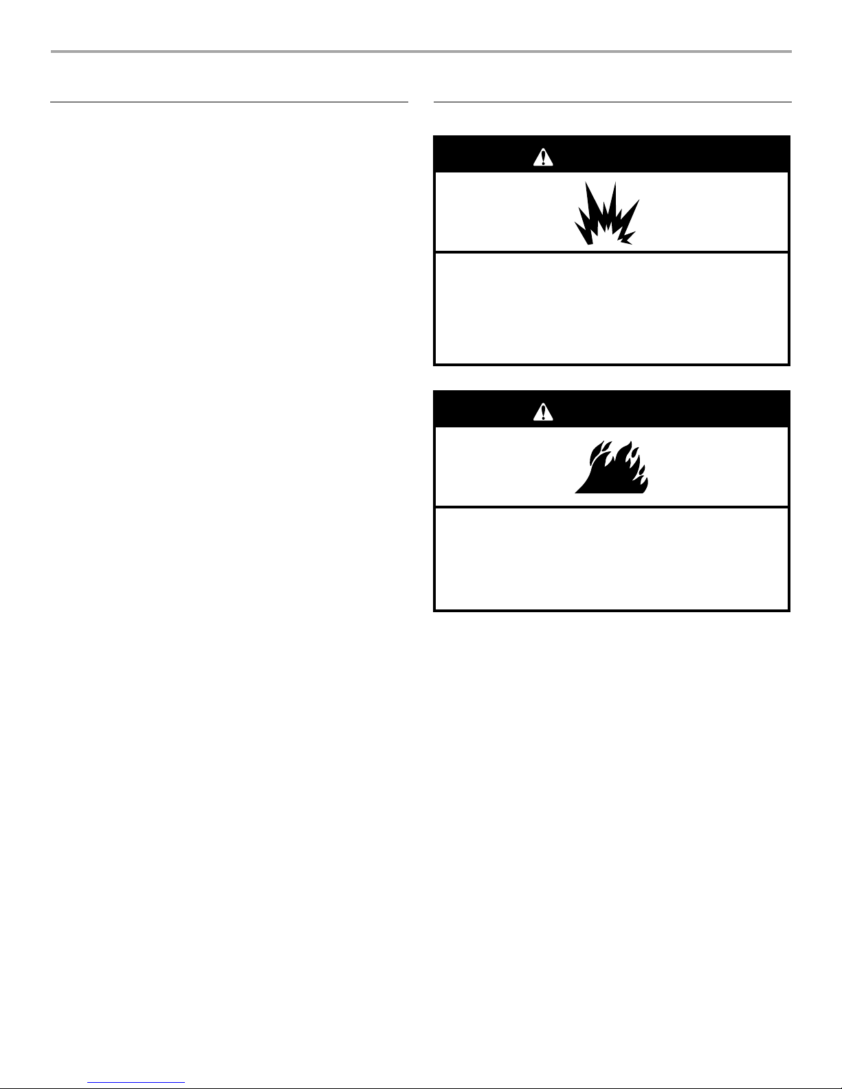
If you smell gas:
1. Shut off gas to the appliance.
2. Extinguish any open flame.
3. Open lid.
4. If odor continues, keep away from the
appliance and immediately call your
gas supplier or your fire department.
DANGER
WARNING
1. Do not store or use gasoline or other
flammable liquids or vapors in the
vicinity of this or any other appliance.
2. An LP cylinder not connected for use
shall not be stored in the vicinity of
this or any other appliance.
State of California Proposition 65 Warnings:
WARNING: This product contains one or more chemicals known to the State of California to cause cancer.
WARNING: This product contains one or more chemicals known to the State of California to cause birth defects or other
reproductive harm.
In the State of Massachusetts, the following installation instructions apply:
■ Installations and repairs must be performed by a qualified or licensed contractor, plumber, or gasfitter qualified or licensed by
the State of Massachusetts.
■ If using a ball valve, it shall be a T-handle type.
■ A flexible gas connector, when used, must not exceed 3 feet.
IMPORTANT: This grill is manufactured for outdoor use only. For grills that are to be used at elevations above 2000 ft (609.6 m) orifice
conversion is required. See “Gas Supply Requirements” section. It is the responsibility of the installer to comply with the minimum
installation clearances specified on the model/serial rating plate. The model/serial rating plate for freestanding models can be found on
the right-hand inside cabinet wall.
3
SAVE THESE INSTRUCTIONS
IMPORTANT SAFETY INSTRUCTIONS
WARNING: To reduce the risk of fire, electrical shock,
injury to persons, or damage when using the outdoor cooking
gas appliance, follow basic precautions, including the
following:
■ Do not install portable or built-in outdoor cooking gas
appliances in or on a recreational vehicle, portable trailer,
boat or in any other moving installation.
■ Always maintain minimum clearances from combustible
construction, see “Location Requirements” section.
■ The outdoor cooking gas appliance shall not be located
under overhead unprotected combustible construction.
■ This outdoor cooking gas appliance shall be used only
outdoors and shall not be used in a building, garage, or any
other enclosed area.
■ Keep any electrical supply cord and fuel supply hose away
from any heated surfaces.
■ Keep outdoor cooking gas appliance area clear and free
from combustible materials, gasoline and other flammable
vapors and liquids.
■ Do not obstruct the flow of combustion and ventilation air.
Keep the ventilation openings of the cylinder enclosure free
and clear from debris.
■ Open the cabinet door and inspect the gas cylinder supply
hose before each use of the outdoor cooking gas
appliance. If the hose shows excessive abrasion or wear,
or is cut, it MUST be replaced before using the outdoor
cooking gas appliance. Contact your dealer and use only
replacement hoses specified for use with the outdoor
cooking gas appliance.
■ Visually check the burner flames.
They should be blue. Slight
yellow tipping is normal for LP
gas. The flames should be
approximately 1" (2.5 cm) high.
■ Check and clean burner/venturi tube for insects and insect
nest. A clogged tube can lead to fire under the outdoor
cooking gas appliance.
■ The LP gas supply cylinder to be used must be:
- constructed and marked in accordance with the
Specification for LP Gas Cylinders of the U.S. Department
of Transportation (DOT) or the National Standard of
Canada, CAN/CSA-B339, Cylinders, Spheres, and Tubes
for Transportation of Dangerous Goods; and Commission.
- provided with a listed overfilling prevention device.
- provided with a cylinder connection device compatible
with the connection for outdoor cooking gas appliances.
■ Always check connections for leaks each time you connect
and disconnect the LP gas supply cylinder. See
“Installation Instructions” section.
■ When the outdoor cooking gas appliance is not in use, the
gas must be turned off at the supply cylinder.
■ Storage of an outdoor cooking gas appliance indoors is
permissible only if the cylinder is disconnected and
removed from the outdoor cooking gas appliance.
■ Cylinders must be stored outdoors and out of the reach of
children and must not be stored in a building, garage, or
any other enclosed area.
■ The pressure regulator and hose assembly supplied with
the outdoor cooking gas appliance must be used. A
replacement pressure regulator and hose assembly
specific to your model is available from your outdoor
cooking gas appliance dealer.
■ Gas cylinder must include a collar to protect the cylinder
valve.
■ For appliances designed to use a CGA791 Connection:
Place a dust cap on cylinder valve outlet whenever the
cylinder is not in use. Only install the type of dust cap on
the cylinder valve outlet that is provided with the cylinder
valve. Other types of caps or plugs may result in leakage
of propane.
If the following information is not followed exactly, a fire
causing death or serious injury may occur.
■ Do not store a spare LP gas cylinder under or near this
outdoor cooking gas appliance.
■ Never fill the cylinder beyond 80 percent full.
1"
(2.5 cm)
4
INSTALLA TION REQUIREMENTS
WARNING
Explosion Hazard
Do not store fuel tank in a garage or indoors.
Do not store grill with fuel tank in a garage or indoors.
Failure to follow these instructions can result in death,
explosion, or fire.
WARNING
Fire Hazard
Do not use grill near combustible materials.
Do not store combustible materials near grill.
Doing so can result in death or fire.
T ools and Parts
Gather the required tools and parts before starting installation.
Read and follow the instructions provided with any tools listed
here.
T ool s Needed
■ Phillips screwdriver
■ Wrench or pliers
■ Pipe wrench
Parts Supplied
■ Gas pressure regulator/hose assembly set for 11” WCP LP gas
■ Right side shelf
■ Left side shelf
■ Side shelf push bar
■ Condiment tray
■ Natural gas orifice for rotisserie/infrared burner
Parts Needed
■ 20 lb LP gas fuel tank - approximately 18" (45.7 cm) height
and 12" (30.5 cm) diameter
Parts Needed for C onversio n to Natura l Gas
■ Natural gas conversion kit Part Number 710-0003. See
“Assistance” section to order. The conversion kit includes:
■ Natural gas regulator 4" W.C. (marked “Natural Gas
Regulator”)
■ 10 ft (3.0 m) Natural gas hose with quick connector
■ 5.9" (150 mm) Natural gas regulator hose
■ 6 mm nut driver
■ 6 mm wrench
■ Allen key
■ Gas line shutoff valve
■ ½" male pipe thread ni pple fo r conne ction t o press ure regu lator.
■ LP gas-resistant pipe- joint compound
■ CSA design-certified outdoor flexible stainless steel appliance
connector (4-5 ft [1.2-1.5 m]) or rigid gas supply line as
needed.
■ Scissors or cutti ng pl iers ( to
remove tiedowns)
■ Noncorrosive leakdetection solution
Location Requirements
Select a location that provides minimum exposure to wind and
traffic paths. The location should be away from strong draft areas.
Do not obstruct flow of combustion and ventilation air.
Clearance to combustible construction for freestanding outdoor
grills:
■ A minimum of 24" (61 cm) must be maintained between the
front of the grill hood, sides and back of the grill and any
combustible construction.
■ A 24" (61 cm) minimum clearance must also be maintained
below the cooking surface, and the grill shall not be used
under overhead combustible construction.
Rotisserie (accessory)*
If you equip your grill with a rotisserie, a 6" (15.2 cm) minimum
clearance is needed for the rotisserie motor.
A grounded, 3-prong outlet located to the left of the grill is
required.
*See “Assistance” section to order.
5
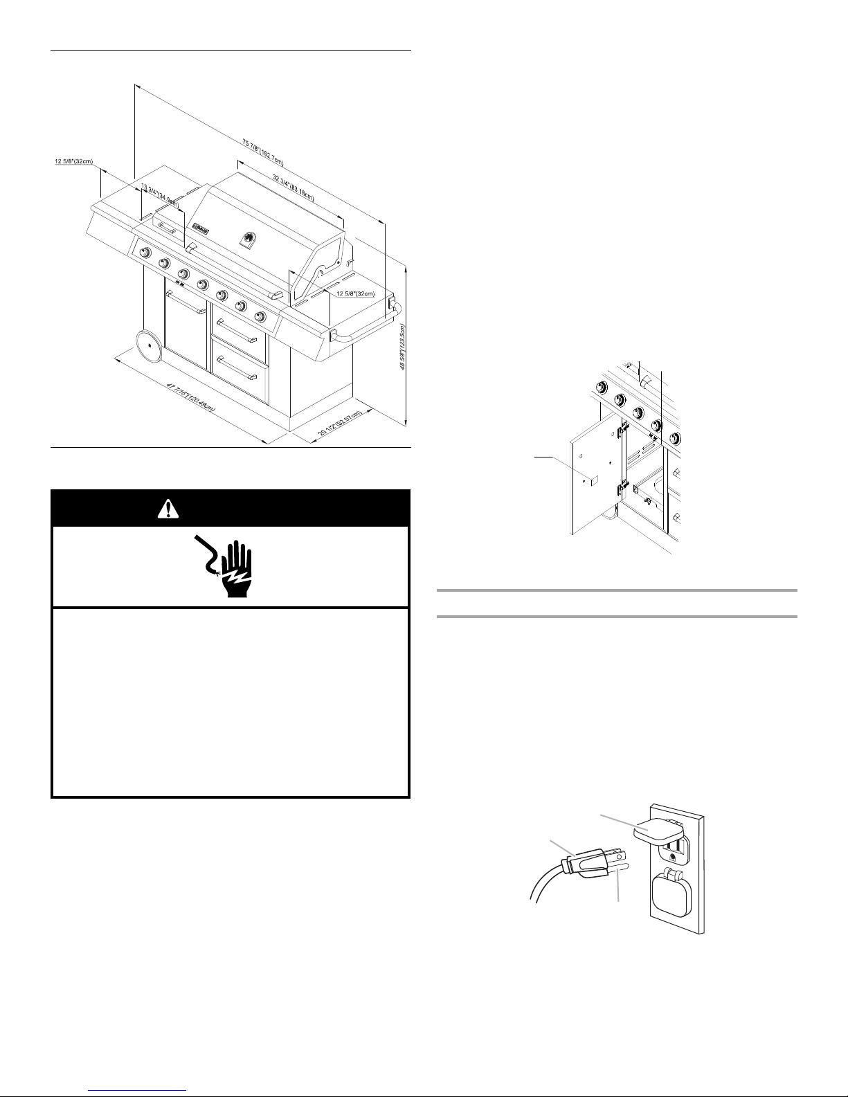
Product Dimensions
Electrical Shock Hazard
Use only a UL listed, 14 gauge, 3 wire extension cord
approved for outdoor use, marked W-A, with a
maximum length of 50 ft.
Plug into a grounded 3 prong outlet.
Do not remove ground prong.
Do not use an adapter.
Failure to follow these instructions can result in death,
fire, or electrical shock.
WARNING
A
A
B
C
■ Do not operate any outdoor cooking gas appliance with a
damaged cord, damaged plug, or after the appliance
malfunctions or has been damaged in any manner. Contact
the manufacturer for repair.
■ Do not let the cord hang over the edge of a table or touch hot
surfaces.
■ Do not use an outdoor cooking appliance for purposes other
than intended.
■ When connecting, first connect plu g to the outdoor cook ing gas
appliance then plug appliance into the outlet.
■ Use only a Grou nd Fa ult In terrupter (GFI) protec ted ci rcuit with
this outdoor cooking gas appliance.
■ Do not remove the ground prong or use with an adapter of
2prongs.
■ Use only extension cords with a 3 prong grounding plug rated
for the power of the equipment and approved for outdoor use
with a W-A marking.
The model/serial number rating plate is located on the inside of
the left cabinet door. See the following illustration.
Electrical Requirements
If codes permit and a separate ground wire is used, it is
recommended that a qualified electrician determine that the
ground path is adequate.
Check with a qualified electrician if you are not sure whether the
grill is properly grounded.
A 120-volt, 60-Hz, AC- only, 15-amp, fused el ectrical supply is
required.
It is recommended that a separate circuit servicing only this grill
be provided.
■ To avoid electrical shock, do not immerse cord or plugs in
water or ot her liquid.
■ Unplug from the outlet when not in use and before cleaning.
Allow to cool before putting on or taking off parts.
6
A.Model/serial number plate
Recommended Ground Method
The outdoor grill, when installed, must be electrically grounded in
accordance with local codes or, in the absence of local codes,
with the National Electrical Code ANSI/NFPA 70, or Canadian
Electrical Code, CSA C22.1.
Copies of the standards listed above may be obtained from:
CSA International
8501 East Pleasant Valley Rd.
Cleveland, Ohio 44131-5 575
National Fire Protection Association
One Batterymarch Park
Quincy, Massachusetts 02269
A.3-prong ground plug
B.3-prong polarized type outdoor GFI outlet
C.Ground prong
Gas Supply Requirements
WARNING
Explosion Hazard
Use a new CSA International approved “outdoor”
gas supply line.
Securely tighten all gas connections.
If connected to LP, have a qualified person make sure
gas pressure does not exceed 11” (28 cm) water
column.
Examples of a qualified person include:
licensed heating personnel,
authorized gas company personnel, and
authorized service personnel.
Failure to do so can result in death, explosion, or fire.
A
A
Observe all governing codes and ordinances.
IMPORTANT: This installation must conform with all local codes
and ordinances. In the absence of local codes, installation must
conform with either the National Fuel Gas Code, ASNI Z223.1/
NFPA 54, Natural Gas and Propane Installation Code, CSA
B149.1, Propane Storage and Handling Code, B149.2, or the
Stan da rd for R e cre ati ona l Vehicles, ASNI A119.2/ NFPA 1192 and
CSA Z240 RV Series Recreational Vehicle Code as applicable.
IMPORTANT: Grill must be connected to a regulated gas supply.
Refer to the model/serial rating plate for information on the type
of gas that can be used. If this information does not agree with
the type of gas available, check with your local gas supplier.
Gas Conversion:
No attempt shall be made to convert the grill from the gas
specified on the model /serial rating plat e for use with a different
gas type without consulting the serving gas supplier. The
conversion kit supplie d with grill m ust be used. See “Gas
Conversions” section for instructions.
Gas Pressure Regulator
The gas pressure regulator supplied with this grill must be used.
The inlet (supply) pressure to the regulator should be as follows
for proper operation:
LP Gas:
Operating pressure: 11" (27.9 cm) WCP
Inlet (supply) pressure: 11" to 14" (27.9 cm to 35.5 cm) WCP
Natural Gas:
Operating pressure: 4" (10.2 cm) WCP
Inlet (supply) pressure: 7" to 14" (17.8 cm to 35.5 cm) WCP
maximum.
Contact local gas supplier if you are not sure about the inlet
(supply) pressure.
Burner Requirements for High Altitude
Input ratings shown on the model/serial rating plate are for
elevations up to 2,000 ft (609.6 m).
For elevations above 2,000 ft (609.6 m), ratings are reduced at a
rate of 4% for each 1,000 ft (304.8 m) above sea level. Orifice
conversion is required. See “Assistance” section to order.
Gas Supply Line Pressure Testing
Testing above ½ psi (3.5 kPa) or 14" (35.5 cm) WCP (gauge):
The grill and its individual shutoff valve must be disconnected
from the gas supply piping system during any pressure testing of
that system at test pressures greater than ½psi (3.5 kPa).
T esting below ½ p si (3.5 kPa) or 14" (35.5 cm) WCP (gauge) or
lower:
The grill must be isolated from the gas supply piping system by
closing its individual manual shutoff valve during any pressure
testing of the gas supply piping system at test pressures equal to
or less than ½ psi (3.5 kPa).
Gas Connection Requirements
20 lb LP Gas Fuel Tank
This grill is equipped for use with a 20 lb LP gas fuel tank (fuel
tank not supplied). A gas pressure regulator/hose assembly is
supplied.
Any brand of 20 lb LP gas fuel tank is acceptable for use with the
grill, provided that it is compatible with the grill’s retention means
(tank tray included).
It is also design-certified by CSA International for local LP gas
supply or for Natural gas with appropriate conversion.
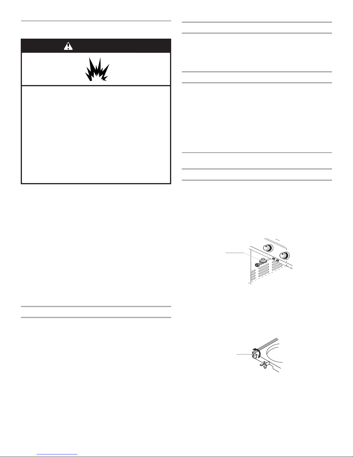
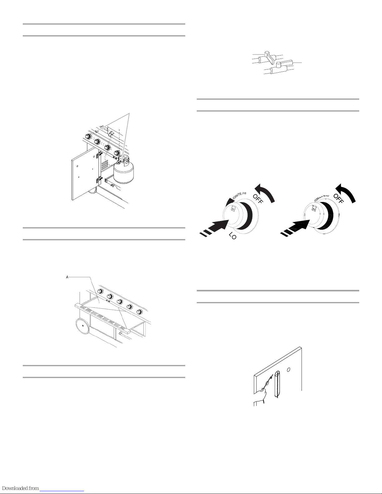
A.Gas pressure regulator/hose assembly
The 20 lb LP gas fuel tank must be mounted and secured.
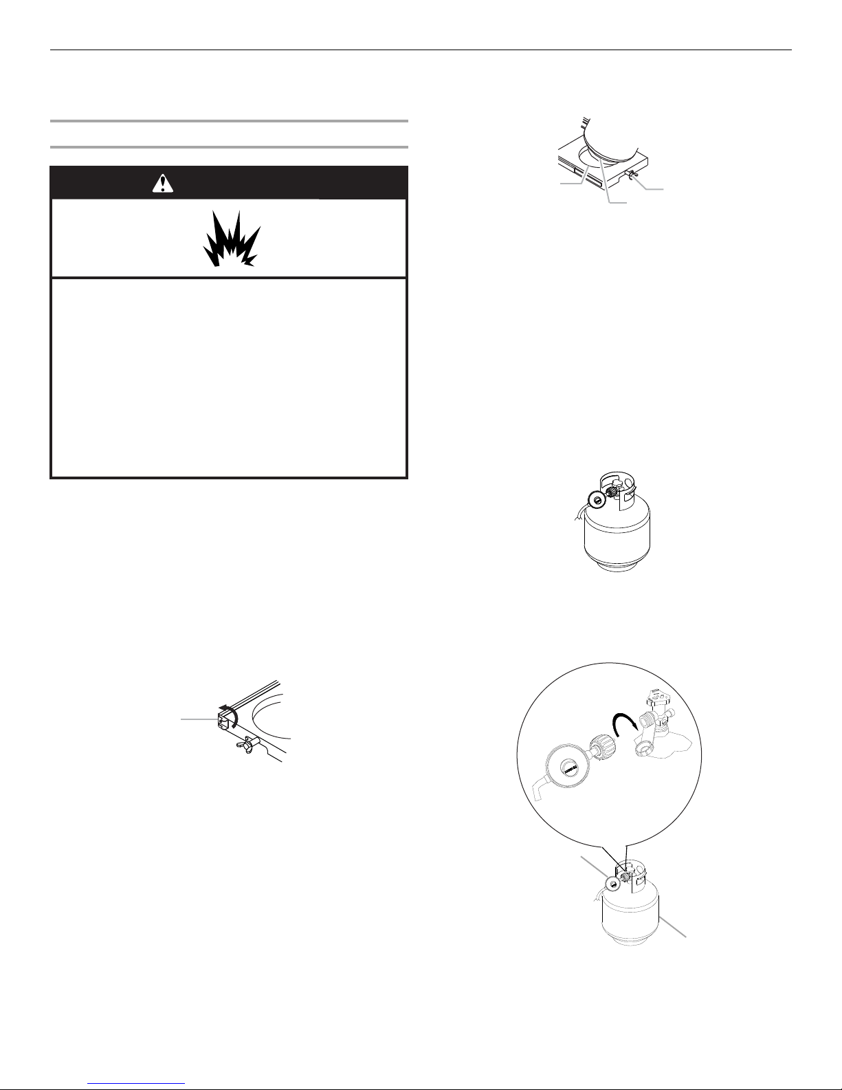
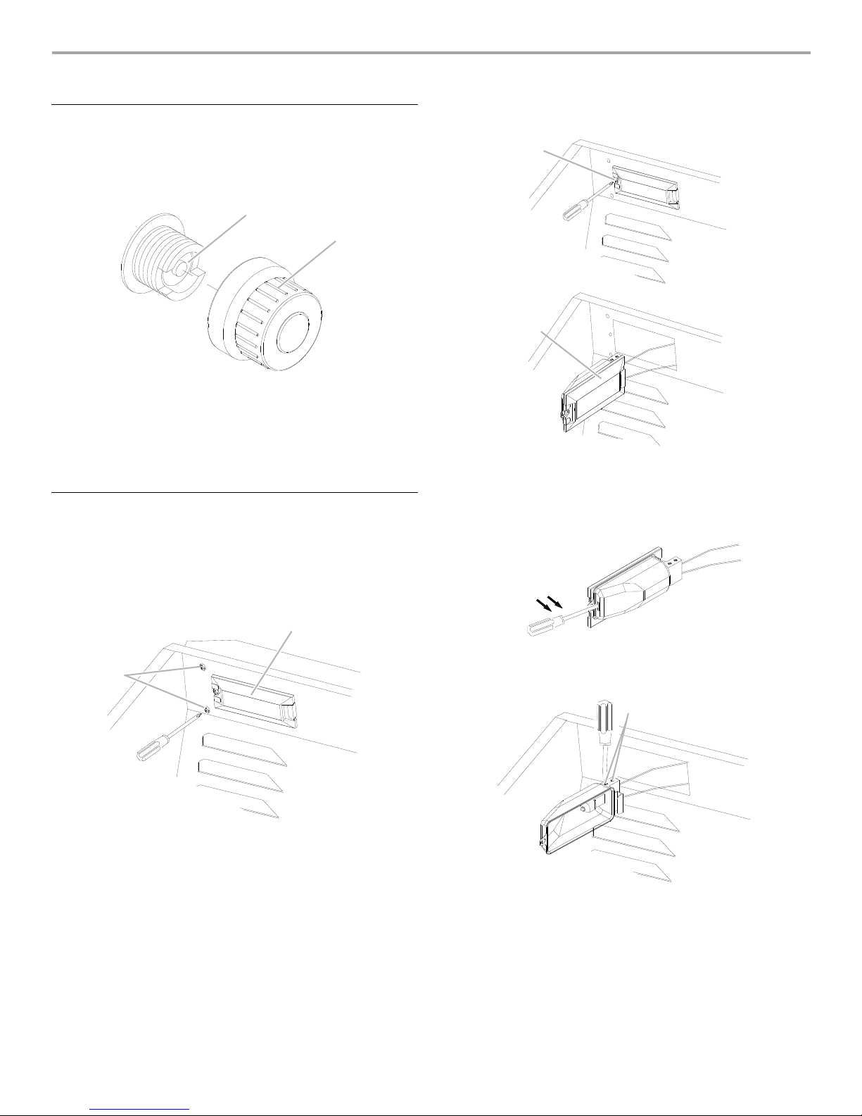
Door Style Tank Tray
1. Open cabinet doors.
2. Slide the tank tray locking bracket counterclockwise 90° and
pull out the tray.
A.Tank tray locking bracker
3. Place the 20 lb LP gas fuel tank bottom collar into the
mounting hole in the tank tray.
7
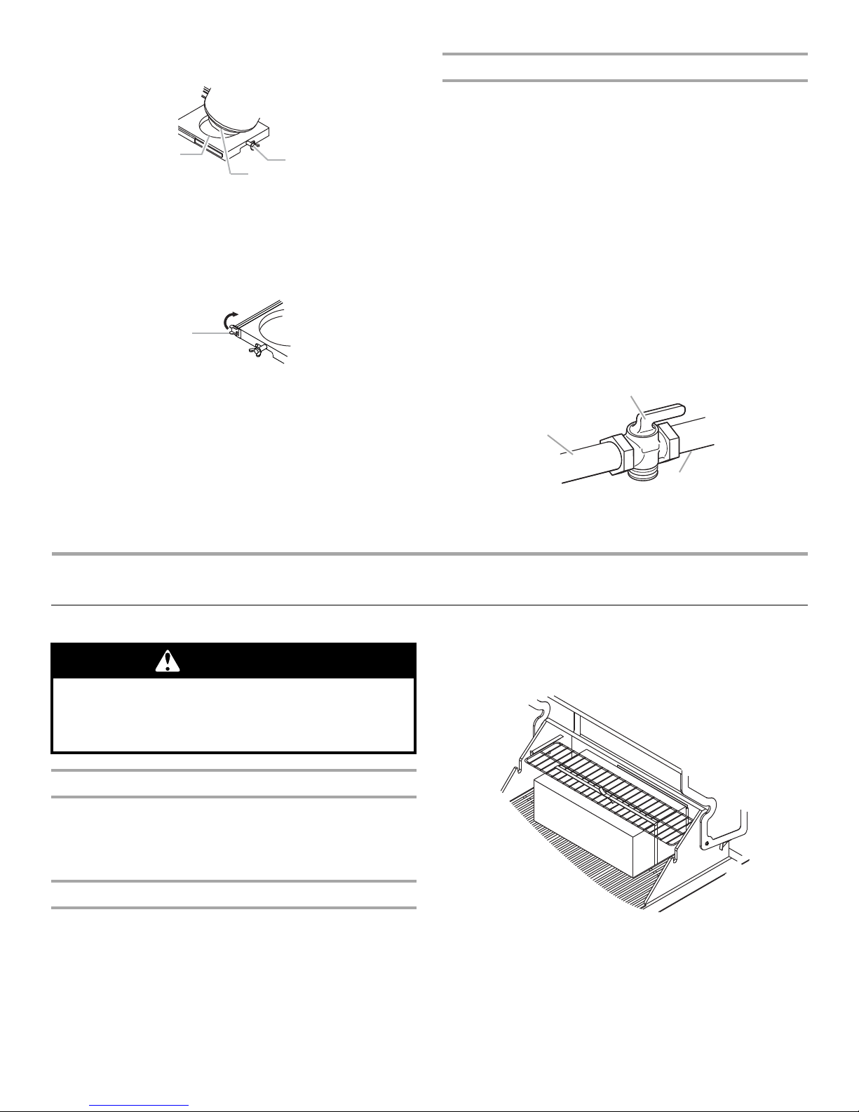
4. Tighten the locking screw against the bottom collar of the
A
C
B
A
A
B
C
Excessive Weight Hazard
Use two or more people to move and install grill.
WARNING
Failure to do so can result in back or other injury.
20 lb LP gas fuel tank to secure.
A.Locking screw
B.Mounting hole
C.Bottom collar
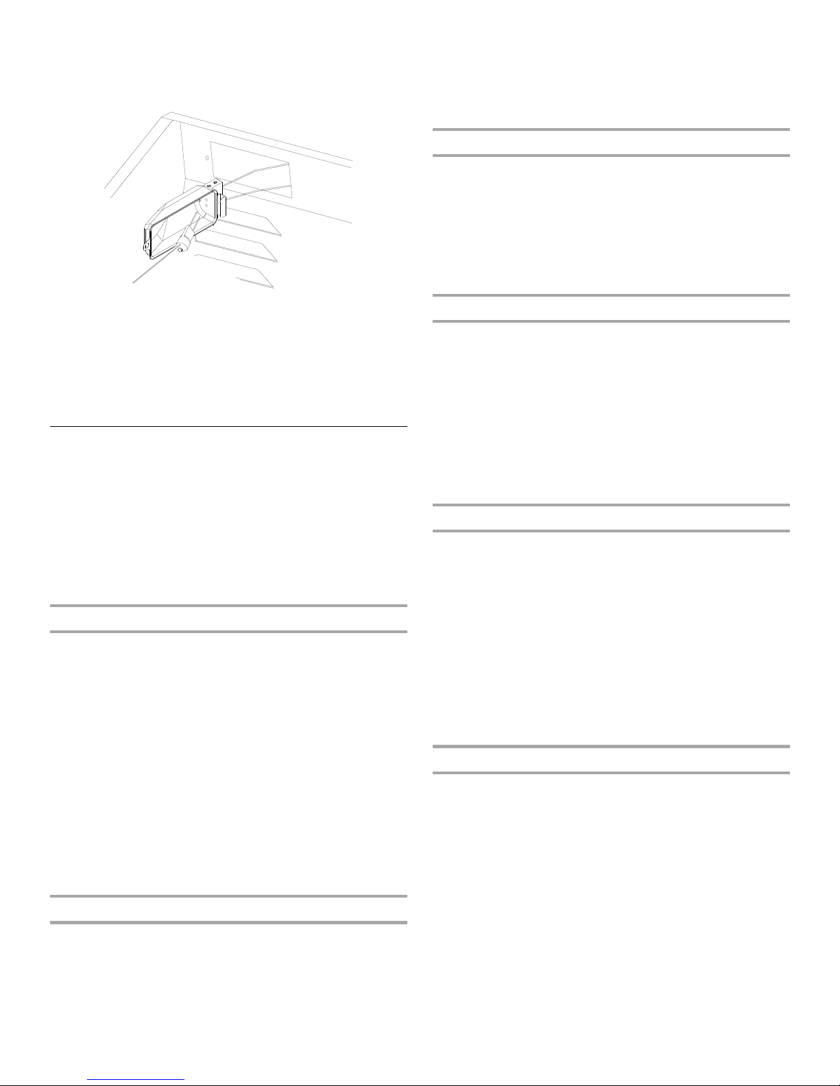
5. Slide the drawer with the 20 lb LP gas fuel tank back into the
cabinet. Turn the tank tray locking bracket clockwise 90° to
tighten.
A.Tank tray locking bracker
Natural Gas Conversion
Conversion must be made by a qualified gas technician. The
qualified Natural gas technician shall provide the Natural gas
supply to the selected grill locati on in accord an ce w ith the
National Fuel Gas Code ANSI Z223.1/NFPA 54 - latest edition,
and local codes. For conversion to Natural gas, the Natural Gas
Conversion Kit supplied with the grill (on some models) or the
Natural Gas Conver sion Kit Part Nu mber 710 -0003 must be used.
See “Assistance” section for information on ordering.
IMPORTANT: The gas ins t allation must conform with local c ode s,
or in the absence of local codes, with the N ational Fu el Gas Code,
ANSI Z223.1/NFPA 54 - latest edition.
Follow instructions for converting to Natural gas in the “Gas
Conversions” section of this manual or the instructions supplied
with Natural Gas Conversion Kit Part Number 710-0003.
The gas supply line shall be equipped with an approved shutoff
valve. This valve should be located in the same area as the grill
and should be in a location that allows ease of opening and
closing. Do not block access to the shutoff valve. The valve is for
turning on or shutting off gas to the grill.
INSTALLA TION INSTRUCTIONS
Freestanding Outdoor Grill Installation
Unpack Gril l
1. Remove all packaging materials and remove grill from the
shipping base.
2. Move grill close to desired outdoor location.
3. Open the grill hood.
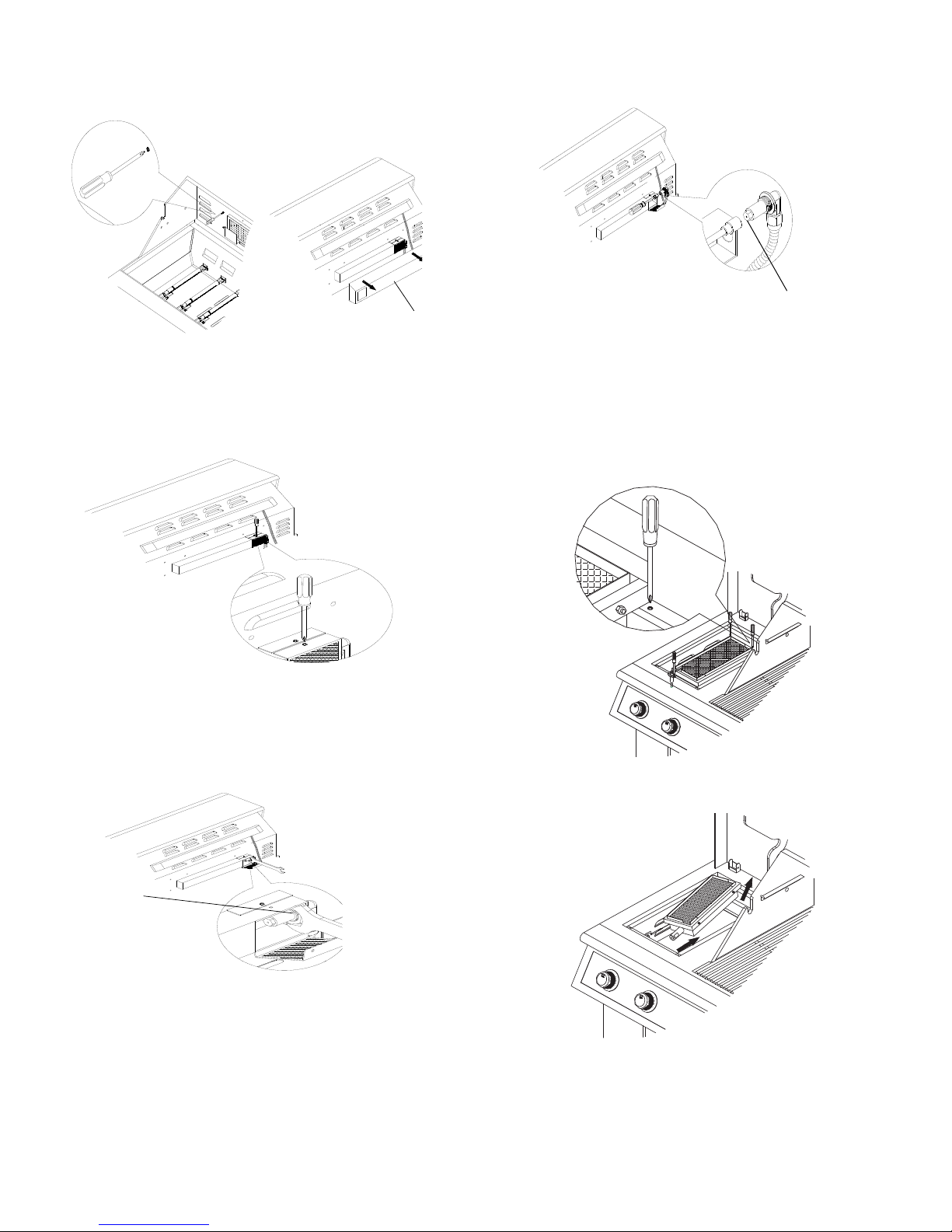
Remove Packaging Materi al Inside the Grill
A.Gas supply line
B.Shutoff valve “open” position
C.To grill
2. Remove the warming shel f and gri ll gr ates from i nside the gril l
and remove the package inside the firebox.
3. Remove foam block and wrap from inside the grill.
1. Use a utility knife to cut yellow straps and packing tape to
open box from top and remove the boxes.
8
4. Replace the grill grates.
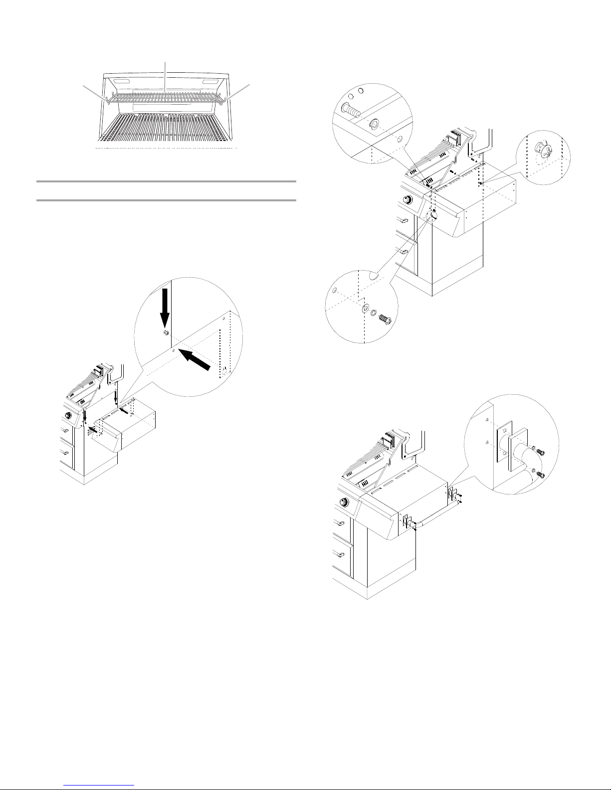
5. Place warming shelf on brackets as shown.
A
B
A
A
B
C
A.Warming shelf brackets
B.Warming shelf
Attach Right Side Shelf
1. Unpack side shelf.
2. Loosen the 2 screws on the side panel and align the bottom
keyhole slots on the side shelf with the loosened screws.
Hook the side shelf onto the two loosened screws and let the
shelf slide down so the screws are in the narrow neck of the
slots.
5. Attach the side shel f to the control p anel (C) by tightenin g the
screw from the side shelf control panel to the main control
panel.
IMPORTANT: This step is meant to help with the installation,
but do not depen d s ol ely o n the tw o sc rew s to hold the weigh t
of the side shelf.
3. Attach the top of the side sh elf to the g rill (A) by in serting thre e
screws into the side shelf from inside the grill hood and
tighten.
4. Attach the bottom of the side shelf to the side pan el (B) of the
grill by tightening the two screws inserted in the keyhole slots
in Step 2.
6. Attach side shelf push bar by aligning the screw holes on the
side shelf with the screw holes in the push bar. Insert the
screws into the push bar screw holes and then into the side
shelf and tighten.
9
Attach Left Side Shelf
A
B
C
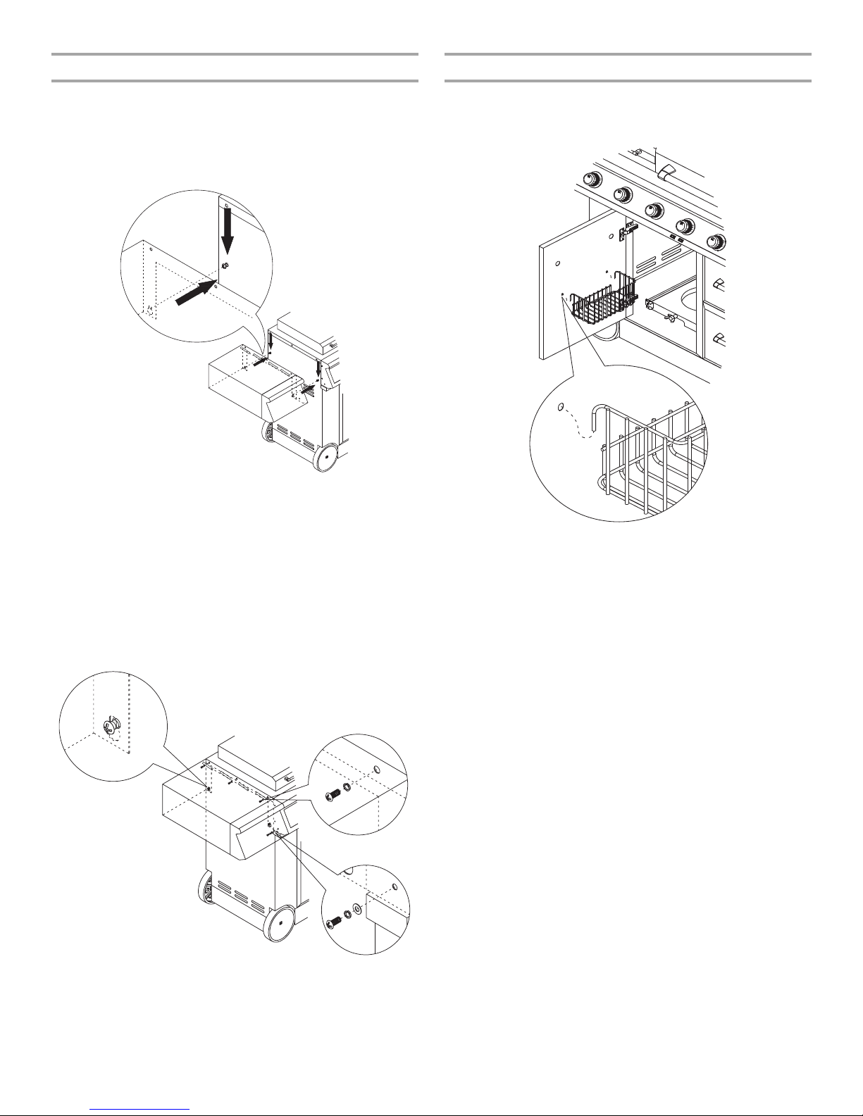
Attach Condiment Tray
1. Unpack side shelf.
2. Loosen the 2 screws on the side panel and align the bottom
keyhole slots on the side shelf with the loosened screws.
Hook the side shelf onto the two loosened screws and let the
shelf slide down so the screws are in the narrow neck of the
slots.
IMPORTANT: This step is meant to help with the installation,
but do not depen d s ol ely o n the tw o sc rew s to hold the weigh t
of the side shelf.
3. Attach the top of the side sh elf (B) to the g rill by in serting three
screws from under the side shelf into the side panel and
tighten.
4. Attach the bottom of the side shelf to the side pan el (A) of the
grill by tightening the two screws inserted in the keyhole slots
in Step 2.
5. Attach the side shelf to the side b urner by ti ghtening the screw
from the side shelf control panel (C) to the side burner.
1. Open cabinet door.
2. Insert hooks on condiment tray into mountin g holes on cabi net
door.
NOTE: It is recommende d to remo ve the c ondiment tra y when
removing or replaci ng the LP tank.
10
Make Gas Connection
WARNING
Explosion Hazard
Securely tighten all gas connections.
If connected to LP, have a qualified person make sure
gas pressure does not exceed 11” (28 cm) water
column.
Examples of a qualified person include:
licensed heating personnel,
authorized gas company personnel, and
authorized service personnel.
Failure to do so can result in death, explosion, or fire.
A
A
C
B
A
B
NOTE: If grill is to be conve rted to Nat ural ga s, fo ll ow instructions
in the “Gas Conversions” section.
20 lb LP Gas Fuel Tank
4. Tighten the locking screw against the bottom collar of the
20 lb LP gas fuel tank to secure.
A.Locking screw
B.Mounting hole
C.Bottom collar
5. Slide the tank tray wit h the 20 lb LP gas fuel tan k bac k in to the
cabinet and lock the locking bracket.
T o Co nnect th e 20 l b LP Gas Fu el Tank:
1. Check that the 20 lb LP gas fuel t ank is in the “Off” position. If
not, turn the valve clockwise until it stops.
2. Check that the 20 lb LP gas fuel tank valve has the proper
type-1 external male thread connections per ANSI Z21.81.
3. Check that the burner control knobs are in the “Off” position.
4. Remove any debris and inspect the valve connections, port,
and gas pressure regulator/hose assembly for damage.
NOTE: Always keep the LP cylinder at 90° (upright)
orientation to provide vapor withdraw.
LP Gas:
IMPORTANT: A 20 lb LP gas fuel tank must be purchased
separately.
IMPORTANT: The gas pressure regulator/hose assembly
supplied with the grill must be used. Replacement gas pressure
regulator/hose assembly specific to your model, is available from
your outdoor grill dealer.
Door Style Tank Tray
1. Open cabinet doors.
2. Slide the tank tray locking bracket counterclockwise 90° and
pull out the tray.
A.Tank tray locking bracker
3. Place the 20 lb LP gas fuel tank bottom collar into the
mounting hole in the tank tray.
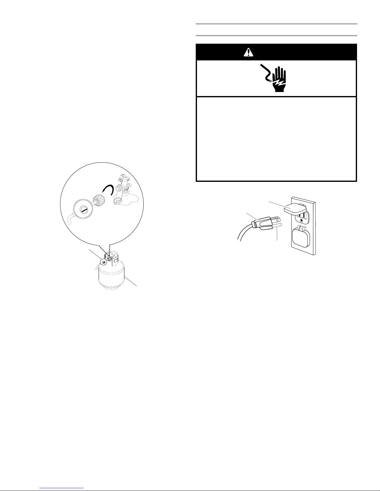
5. Using your hand, turn the gas pressure regulator/hose
assembly clockwis e to connect to the 20 lb LP ga s fuel tank as
shown.
Hand tighten only. Use of a wrench could damage the quick
coupling nut.
A.20 lb LP gas fuel tank
B.Gas pressure regulator/hose assembly
Make sure that the cylinder valve connection device properly
mates with the connection device attached to the inlet of the
pressure regulator.
11
6. Open the tank valve fully by turning the valve
A
B
Electrical Shock Hazard
Use only a UL listed, 14 gauge, 3 wire extension cord
approved for outdoor use, marked W-A, with a
maximum length of 50 ft.
Plug into a grounded 3 prong outlet.
Do not remove ground prong.
Do not use an adapter.
Failure to follow these instructions can result in death,
fire, or electrical shock.
WARNING
A
B
C
counterclockwise. Wait a few minutes for gas to move through
the gas line.
7. Before lighting the grill, test all con nec tio ns by brus hin g on an
approved noncorrosive leak-detection solution. Bubbles will
show a leak.
8. If a leak is found, turn the tank valve off and do not use the
grill. Contact a qualified gas technician to make repairs.
9. Go to “Check and Adjust the Burners” section.
T o Di sconnect t he 20 lb LP Gas Fuel Tank:
1. Check that the burner control knobs are in the “Off” position
and the grill is cool.
2. Check that the 20 lb LP gas fuel tank is in the “Off” position. If
it is not, turn the valve clockwise until it stops.
3. Using your hand, tur n the gas pressure regulator/hose
assembly counterclockwise to disconnect to the 20 lb LP gas
fuel tank as shown.
Hand loosen only. Use of a wrench could damage the quick
coupling nut.
Plug in Grill
1. Plug extension cord into grounded 3-prong GFI outlet.
A.Gas pressure regulator/hose assembly
B.20 lb LP gas fuel tank
4. Place dust cap on cylinder valve outlet whenever the cylinder
is not in use. Only install the type of dust cap on the cylinder
valve outlet that is provided with the cylinder valve. Other
types of caps or plugs may result in leak age of propane.
5. Go to “Plug in Grill” in this section.
12
A.3-prong ground plug
B.3-prong polarized type outdoor GFI outlet
C.Ground prong
■ To avoid electrical shock, do not immerse cord or plugs in
water or other liquid.
■ Unplug from the outlet when not in use and before
cleaning. Allow to cool be fore putt ing on or taking off p art s.
■ Do not operate any outdoor cooking gas appliance with a
damaged cord, damaged plug, or after the appliance
malfunctions or has been damaged in any manner.
Contact the manufacturer for repair.
■ Do not let the cord hang over the edge of a table or touch
hot surfaces.
■ Do not use an outdoor cooking appliance for purposes
other than intended.
■ When connecting , first c onnect p lug to th e outd oor cook ing
gas appliance then plug appliance into the outlet.
■ Use only a Grou nd Fault Interrupter ( GFI) protected circuit
with this outdoor cooking gas appliance.
■ Do not remove the ground prong or use w i th a n adapter of
2prongs.
■ Use only extension cords with a 3 prong grounding plug
rated for the power of the equipment and approved for
outdoor use with a W-A marking.
2. Go to “Check and Adjust the Burners” section
GAS CONV ERSIONS
WARNING
Explosion Hazard
Use a new CSA International approved “outdoor”
gas supply line.
Securely tighten all gas connections.
Failure to do so can result in death, explosion, or fire.
†®TEFLON is a registered trademar k of E.I . Du Pont De Nemo ur s an d Compa ny.
T ools and Parts for Gas Con version
Gather the required tools and parts before starting installation.
Read and follow the instructions provided with any tools listed
here.
T ools n eeded
■ Phillips screwdriver
■ Pipe wrench
■ Adjustable wrench
■ 6 mm socket and wrench or
6 mm nut drive r
Parts supplied
■ Natural gas orifices
Parts needed
■ Natural gas conversion kit Part Number 710-0003. See
“Assistance” section to order. The conversion kit includes:
■ Natural gas regulator 4" W.C. (marked “Natural Gas
Regulator”)
■ 10 ft (3.0 m) Natural gas hose with quick connector
■ 5.9" (150 mm) Natural gas regulator hose
■ 6 mm nut driver
■ 6 mm wrench
■ Allen key
IMPORTANT: Gas conversions must be done by a qualified
installer. Before proceeding with conversion, shut off the gas
supply to the applianc e p r ior to dis connecting the electrica l po we r.
■ Thin flat-blade screwdriver
■ Pliers
■ Pipe thread sealant
certified for LP gas
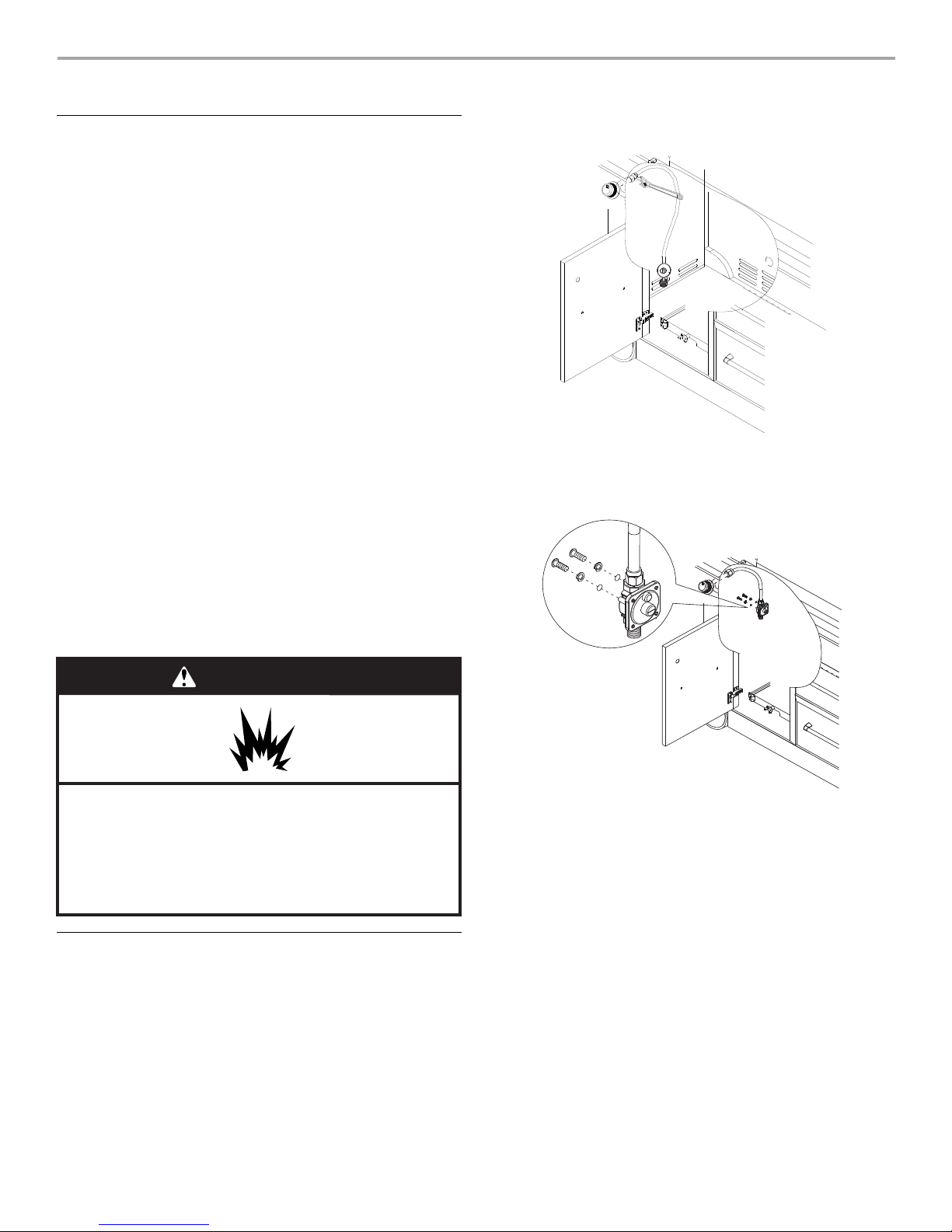
6. Use an adjust able wr ench to remove the L P regul ator from the
manifold.
7. Use an adjustable wrench to install the Natural gas regulator
hose to the manifold and secure. Attach the Natural gas
regulator to the side panel inside the grill cart with the two
screws that are preassembled on the regulator.
Conv ersion from LP Gas to Natural Gas
Installation of the regulator
1. Turn off the main gas supply valve.
2. Unplug grill or disconnect power.
3. Disconnect 20 lb LP gas fuel tank (if present).
4. Turn off all burner control valves.
5. Remove the 20 lb LP gas fuel tank (if present) from the grill
cart.
Make Gas Connection
1. A combination of pipe fitti ngs must be used to connec t the grill
to the existing gas line.
■ The 10 ft (3.0 m) PVC flexible gas supply hose design-
certified by CSA must be used.
■ Pipe-joint compounds suitable for use with Natural gas
must be used. Do not use Teflon®† tape.
■ There must be a certified manual shutoff valve in the gas
supply line near the grill for easy ac cess.
2. Connect the brass connector on one end of the 10 ft (3.0 m)
PVC flexible gas supply hose to the Natural gas pressure
regulator.
13
3. Connect the quick connector on the other end of the
A
B
C
D
A
A
Wind Baffle
10 ft (3.0 m) PVC flexible gas supply hose to the rigid Natural
gas supply pipe.
A.Manifold
B.Left side panel
C.Natural gas pressure regulator/hose assembly
D.10 ft (3.0 m) PVC gas hose
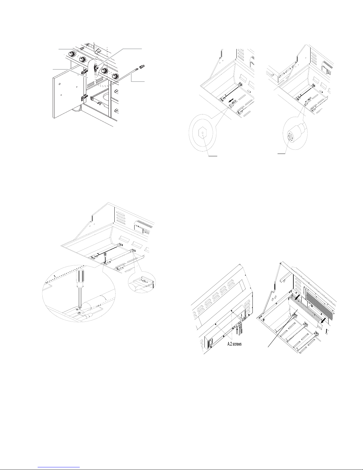
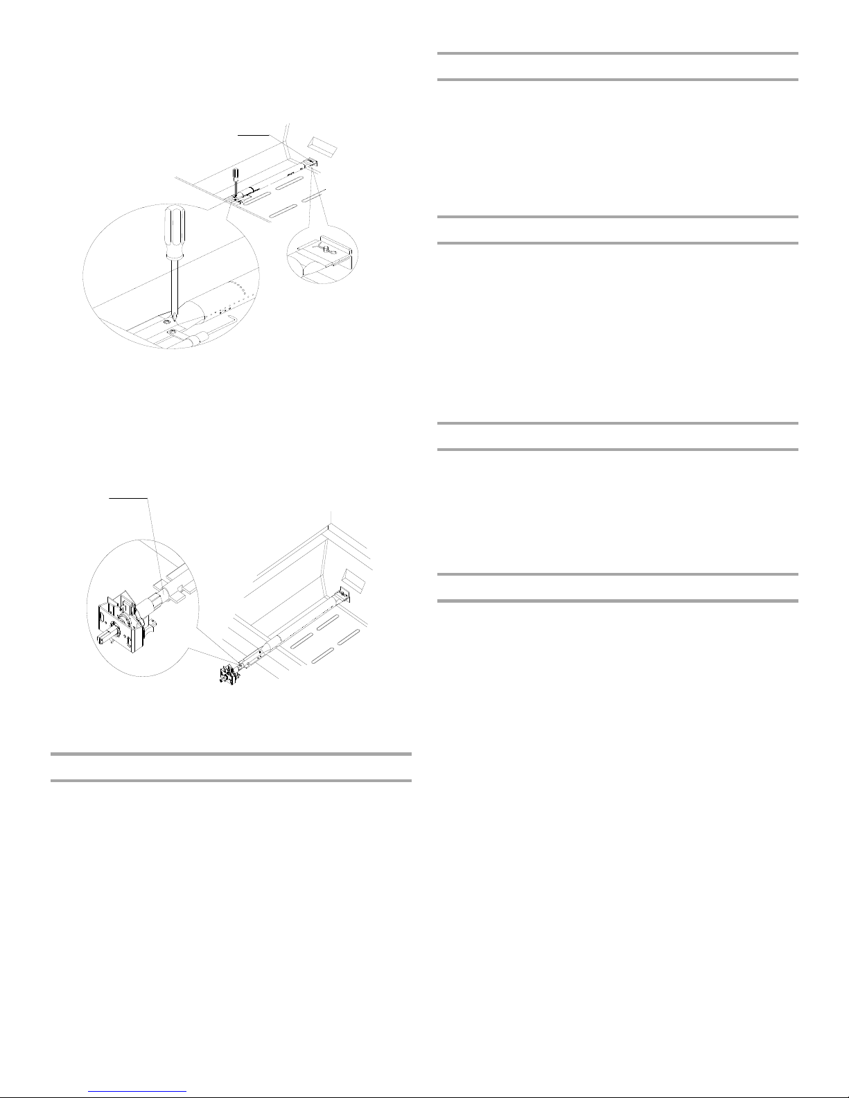
3. Use a 6 mm socket and wrench or 6 mm nut driver to remove
the brass orifice from the end of gas valve. The main burner
orifice is located behind the LP orifice, so no additional orifice
needs to be installed.
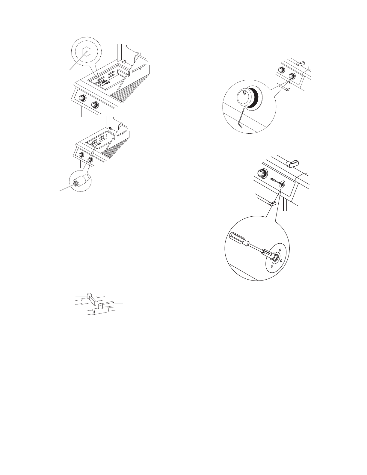
Change Grill Burner Valve Orifices
1. Remove the grates and flame tamers.
2. Remove 1 screw and clip that hold the burner in place. Set the
screw and clip aside. Remove the burner from the grill by
lifting the burner out.
A.Main burner orifice
IMPORTANT: Check that the o rifice is properly inst alled i nside
of the burner opening.
4. Reinsert the burner and reattach using the screw and the clip
previously removed. Repeat the procedure for each main
burner.
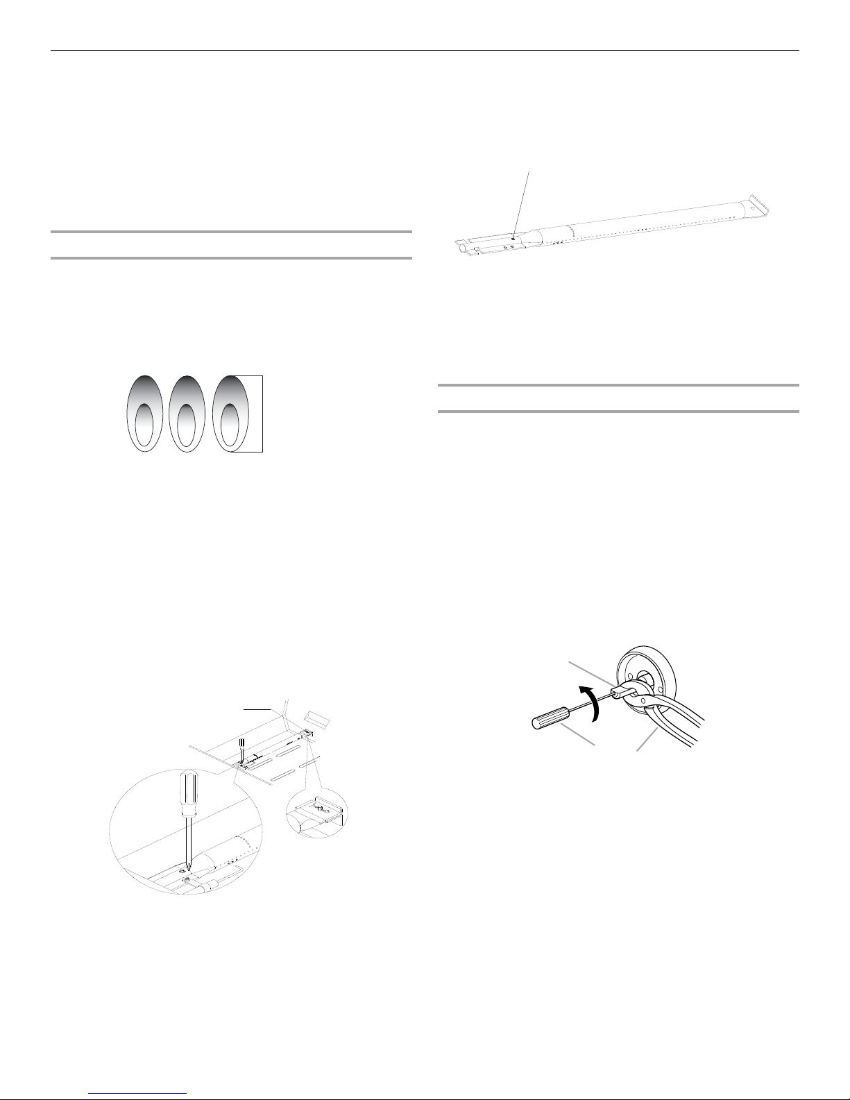
5. Position the igniters so they are ¼" (6.0 mm) away from each
burner.
Change the Rotisserie/ Infrared Burner O rifice
1. Using a Phillips screwdriver, unscrew the 2 screws and
remove the rotisserie/infrared burner wind baffle.
14
2. Remove the access cover at the back of the grill by removing
A
A
Orifice
the 6 screws at the back of firebox.
5. Take out the orifice support, and then use a 6 mm socket and
wrench or 6 mm nut driver to remove the LP orifice at the end
of the supply pipe. Replace with Natural gas orifice.
A.Access cover
3. Using a Phillips screwdriver, remove the screw holding the
spider guard to the burner.
4. Use 24 mm wrench to remove the orifice nut.
IMPORTANT: Check that the o rifice is properly inst alled i nside
of the supply pipe.
6. Reinstall the spider guard, access cover, and wind baffle.
Change the Sear Burne r Orific es
1. Remove the 2 screws securing the igniter and remove the
igniter from the side burner.
2. Remove the searing side burner screws. Set the screws and
cover aside.
A.Orifice nut
3. Lift the searing side burner out of the grill.
15
4. Use 6 mm socket wrench or 6 mm nut driver to remove the
A
A
A
B
orifice. Replace with the Natural gas orifice.
Adjust High Flame Setting Screw
When converting from LP to Natural gas, you will need to adjust
the high flame setting screw for ideal burner flame height.
1. Remove each control knob for the main burners and s ide
burner by loosening the setscrew with the Allen key.
2. Use a flat-blade screwdriver to turn the high flame setscrew
counterclockwise approximate 90°.
A.Orifice
IMPORTANT: Check tha t the orifice is properl y installed ins ide
of the valve.
5. Reinstall the searing side burner. Ma ke sure tha t the igniter is
out of the way to allow proper positioning of burner. Use
Phillips screwdriver to attach the mo unti ng screws.
6. Use Phillips screwdriver to reattach the igniter and searing
side burner plate.
7. Reinstall searing side burner cover. Use Phillips screwdriver
to attach mounting screws.
8. Open the manual shutoff valve in the gas supply line. The
valve is open when the handle is parallel to the gas pipe.
A.Closed valve
B.Open valve
9. Test all connections using an approved noncorrosive leakdetection solution. Bubbles will show a leak. Correct any leak
found.
Record Conversion
1. The appliance nameplate is located inside the grill cabinet on
the left-hand cabinet side. With a permanent marker, check
the box next to “Natural gas” and mark through “LP Propane.”
In the last page of the Use and Care Guide, write “Converted to
Natural Gas.” Also record the conversion date and the technician/
company that performed the conversion.
NOTE: Place LP gas parts in plastic parts bag for future use and
keep with pack containing literature.
3. Check that burner operates at the new high flame setting. It
may be necessary to adjust the screw setting slightly more to
get the ideal burner flame height.
16
Check and Adjust the Burners
1" (2.5 cm)
A
A
A
B
C
The burners are tested and factory-set for most efficient
operation. Howeve r, variations in gas supply and ot he r con dit ion s
may make minor adjustments to air shutter or low flame setting
necessary.
It is recommended that a qualified person make burner
adjustments.
NOTE: The rotisserie burner cannot be adjusted.
Checking and adjusting the grill burner flames requires removing
the grates and flame tamers.
Burner Flame Characteristics
6. If flame is yellow (not enough air), turn air shutter adjustment
screw counterclockwise.
If flame is noisy or lifts away from burner (too much air), turn
air shutter adjustment screw clockwise.
The flames of the g rill burne rs and sid e burner s (on some m odels)
should be blue and stable with no excessive noise or lifting (LP
gas flames will h ave a sli ghtly y ellow t ip). A yello w fla me indic ates
not enough air . If flame is noisy or lif ts awa y from the burner, there
is too much air . Some yel low tips on flames when the burn er is set
to HI setting are accept abl e as lon g as no c arbon or s oot depo sit s
appear. The flames should be approximately 1" (2.5 cm) high.
Check that burners are not blocked by dirt, debris, insect nests,
etc., and clean burners as necessary. If they are clean, adjust air
shutters as needed.
IMPORTANT: Before adjusting air shutters, let burners cool
completely.
To Adjust:
1. Light grill using information in the “Outdoor Grill Use” section.
2. Observe flame to determine which burners need adjustment
and how the flame is acting.
3. Turn off the valve and wait until grill and burners cool
completely.
4. Remove grill grates and flame tamers.
5. Remove 1 screw and clip that hold the burner in place.
Remove gas burner from the grill.
A.Air shutter adjustment screw
Adjustment should be made clockwise or counterclockwise
from 1/8" (3.2 mm) to 1/4" (6.4 mm).
7. Replace gas burner, flame tamers and grates.
8. Light grill using information in the “Outdoor Grill Use” section.
See “Burner Flame Characteristics. ”
Low Flame Adjustment
If flame goes out on the “LOW ” setting , the low flam e settin g must
be adjusted.
1. Turn off the valve and wait until grill and burners are cool.
2. Remove grill grates and flame tamers.
3. Light grill using information in the “Outdoor Grill Use” section.
4. Turn burner to its lowest setting.
5. Remove each control knob for the main burners and s ide
burner by loosening the setscrew with the allen key.
6. Hold valve stem with pliers and insert a small flat-blade
screwdriver into the shaft.
7. Watch the flame and slowly turn the screwdriver
counterclockwise.
8. Adjust flame to minimum stable flame.
A.Clip
A.Valve stem
B.Small flat-blade screwdriver
C.Pliers
9. Replace the control knob and turn off the burner.
10. Repeat steps 3 through 9 for each burner if needed.
11. Replace the flame tamers and grates after the burners have
cooled.
17
OUTDOOR GRILL USE
WARNING
Explosion Hazard
Do not store fuel tank in a garage or indoors.
Do not store grill with fuel tank in a garage or indoors.
Failure to follow these instructions can result in death,
explosion, or fire.
WARNING
Fire Hazard
Do not use grill near combustible materials.
Do not store combustible materials near grill.
Doing so can result in death or fire.
WARNING
Food Poisoning Hazard
Do not let food sit for more than one hour before or
after cooking.
Doing so can result in food poisoning or sickness.
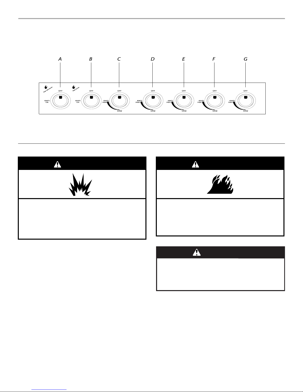
This manual co vers s everal d if fere nt mod els. T he gril l you have purch ase d may h ave s ome o r al l of th e featu res li st ed. The loca tio ns and
appearances of the features shown here may not match those of your model.
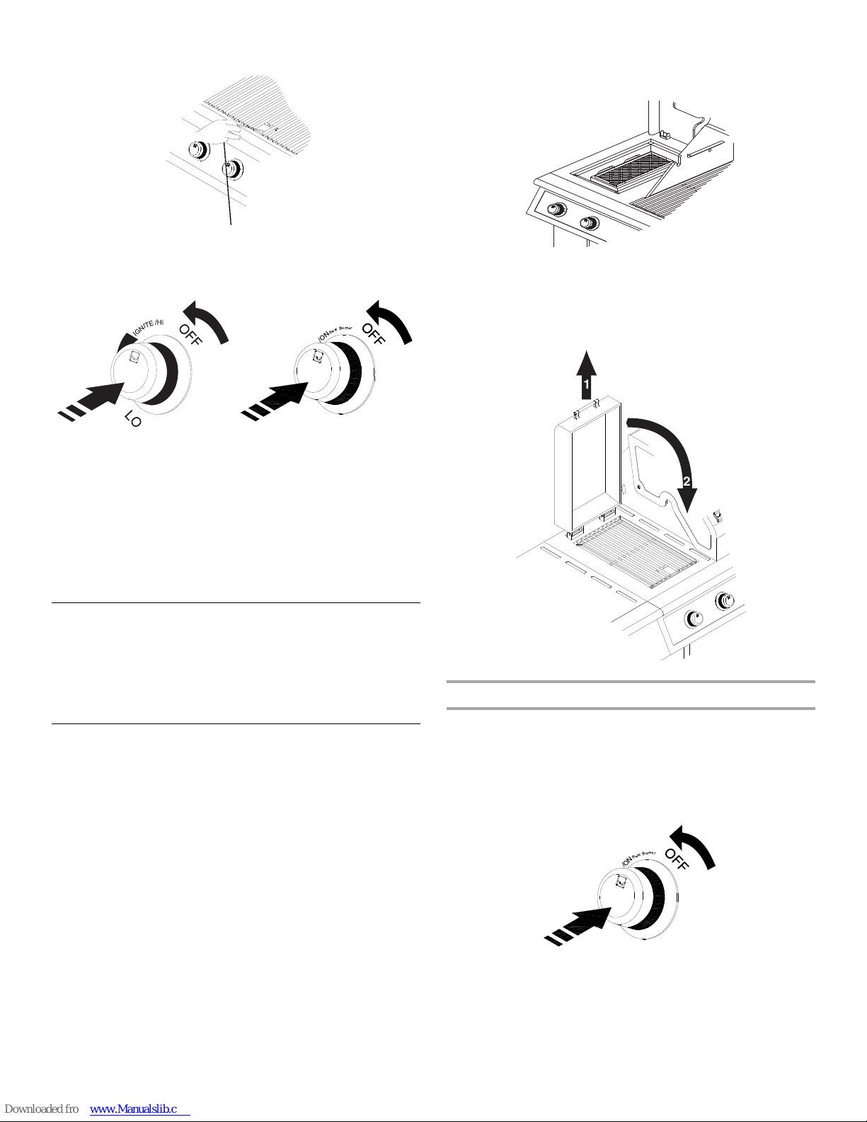
Control Panel
A.Sear burner control knob
B.Rotisserie burner control knob
C.Main burner control knob
D.Main burner control knob
E.Main burner control knob
F. Main burner control knob
G. Main burner control knob
Using Y our Outdoor Grill
18
Inspect the LP Gas Fuel Tank Supply Hose
A
A
B
W
GH
O
F
F
/O
N
R
e
a
B
u
r
n
e
r
r
Inspect the gas pressure regulator/hose assembly before each
use.
1. Open the cabinet door.
2. Inspect the gas pressure regulator/hose assembly for cuts,
abrasions, or excessive wear.
3. If necessary, replace the gas pressure regulator/hose
assembly before using the grill.
Contact the dealer and use only replacement hoses specified
for use with the grill.
2. For outdoor grills us in g g as s up ply s ourc e o the r tha n 20 lb LP
gas fuel tank:
Open the manual shutoff valve in the gas supply line. T he
valve is open when the handle is parallel to the gas pipe.
A.Closed valve
B.Open valve
Lighting the Grill and Searing Side Burner
IMPORTANT: If burner does not light immed iately, turn the burner
knob to OFF and wait 5 minutes before relighting.
1. Open the hood completely. Do not light burners with the hood
closed.
2. Do not lean over the grill.
3. Select the burner you want to light. Push in and turn the grill
burner control knob to IGNITE/HIGH or IGNITE/ON, while
continuing to hold it in.
A.Gas pressure regulator/hose assembly
Prepare the Gril l for Lig hting
1. Open the hood completely. Do not light burners with the hood
closed.
2. Make sure control knobs are turned to OFF . The drip tray must
be in place and pushed all the way to the back.
A.Drip tray
T ur n the Gas Suppl y On
1. For outdoor grills using a 20 lb LP gas fuel tank:
Slowly open the tank valve.
NOTE: If flow limiti ng devi ce ac tivate s, you r grill m ay not ligh t.
If your grill does light, the flames will be low and will not heat
properly. Turn tank valve and all control knobs off and wait 30
seconds. After shutting off the tank, very slowly open tank
valve and wait 5 seconds before lighting.
4. You will hear the “snapping” sound of the spark. When burner
is lit, release the knob. Turn knob to desired setting.
5. Repeat for each of the other burners as needed.
IMPORTANT: If burner does not light immediately, turn the
burner knob to OFF and wait 5 minutes before relighting.
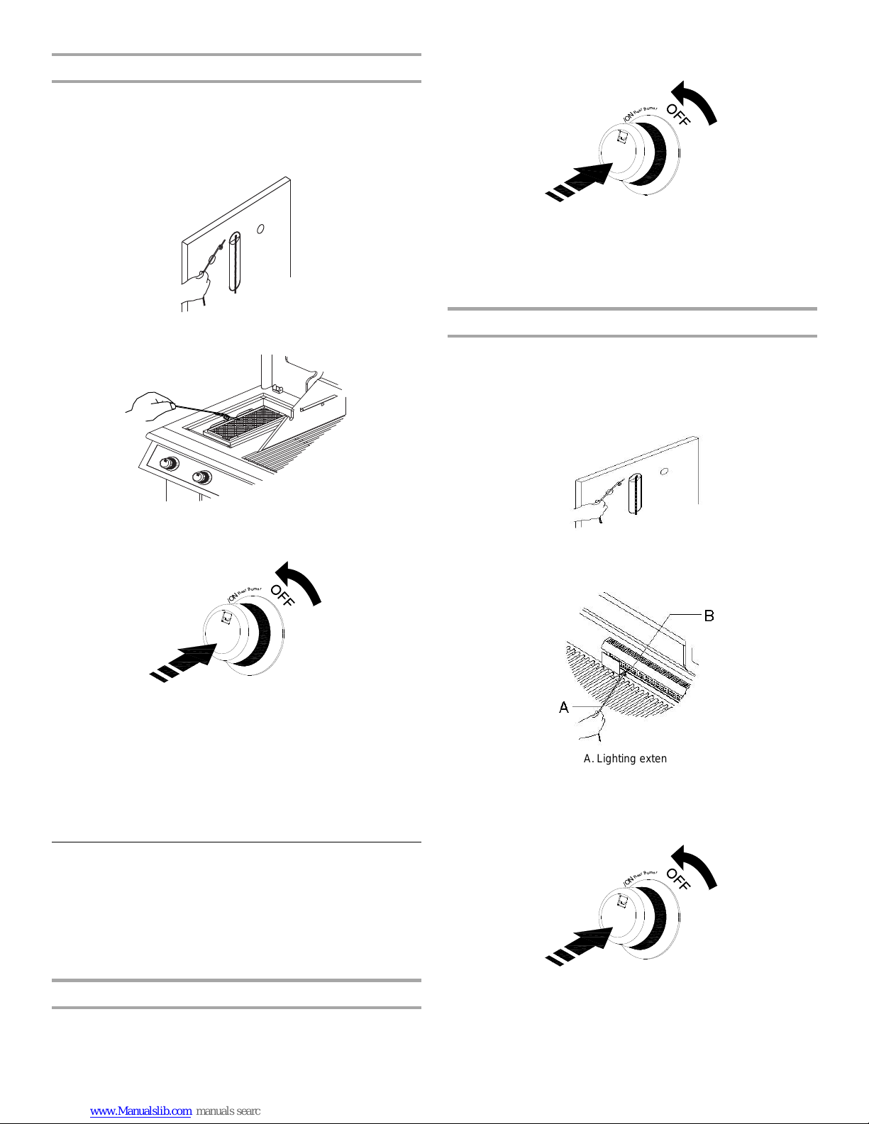
Manually Lighting the Grill and Searing Side Burner
1. Open the hood completely. Do not light burners with the hood
closed.
2. Do not lean over the grill.
3. Remove the manual lighting extension (see following
illustration) and attach a match to the split ring.
4. Strike the match to light it.
19
5. Guide the lit match under the grill grate.
O
F
F
/O
N
R
e
a
B
u
r
n
e
r
r
1
2
O
F
F
/O
N
R
e
a
B
u
r
n
e
r
r
6. Push in and turn the burner knob to IGNITE/HIGH or IGNITE/
ON for the burner closest to the lit matc h. Th e burn er w ill li ght
immediately. When burner is lit, turn knob to desired sett ing.
GH
W
7. Repeat steps 3 through 6 for each main burner.
8. Remove match and replace manual lighting extension on the
right side panel.
IMPORTANT:
If burner does not light immediately, turn the burner knob to OFF
and wait 5 minutes before relighting.
If any burners do not light after attempting to light them manually,
contact the Customer Service Center. See the “Assistance”
section.
■ Use the sear burner to sear me at 1 to 2 min utes on e ach sid e,
then move the meat to the main grill cooking surface to finish
grilling to the desired doneness.
IMPORTANT: It is recommended that the sear side burner lid
be raised when the b urne r is in us e t o el im ina te the possibility
of increased lid and handle temperatures.
■ T o close the searing side burner lid, first lift up the lid to release
the lock then lower it to the closed position.
Hood Lights
The grill must be plu gg ed i n fo r the hood lights to work. See “Plug
in Grill” in the “Freestanding Outdoor Grill Installation” section.
To Us e:
Press the LIGHTS button on the control panel to turn the hood
lights on and off.
Using Y our Searing Side Burner
Infrared grilling produces intense heat which quickly sears the
meat. Searing locks in flavor and juices while allowing the outer
surface to absorb smoke and food aroma that is produced as
grease and drippings are vaporized by the burner. The result is a
crisp, flavorful outside with a tender, juicy inside.
■ Preheat the infrared sear burner for 5 minutes.
■ Ensure that meats are fully thawed and that all excess fat is
trimmed away prior to grilling.
■ Leave the burner set to HI when placing food on the grill to
sear.
Lighting the Searing Side Burner
1. Remove the searing side burner cover. Do not light burners
with the cover on.
2. Do not lean over the grill.
3. Push in and turn the control knob to IGNITE/ON and hold in.
Y ou will hear the “snapping” sound of the spark. When burner
is lit, release the knob. Turn knob to desired setting.
IMPORTANT: If burner does not light immed iately, turn the burner
knob to OFF and wait 5 minutes before relighting.
20
Manually Lighting the Searing Side Burner
O
F
F
/O
N
R
e
a
B
u
r
n
e
r
r
O
F
F
/O
N
R
e
a
B
u
r
n
e
r
r
O
F
F
/O
N
R
e
a
B
u
r
n
e
r
r
1. Remove the searing side burner cover. Do not light burners
with the cover on.
2. Do not lean over the grill.
3. Remove the manual lighting extension (see following
illustration) and attach a match to the split ring.
3. Push in and turn the contro l knob to IGNITE/ ON. You will hear
the “snapping” sound of the spark.
4. When the rotisserie burner lights, continue to hold the knob in
for another 10 seconds, th en re lea se the k no b an d burner will
stay lit. You will hear the “snapping” sound of the spark until
the knob is released.
IMPORTANT: If the rotisserie burner does not light immediat ely,
turn the burner knob to OFF and wait 5 minutes before relighting.
4. Strike the match to light it.
5. Hold the lit match close to the searing side burner.
6. Push in and turn the burner knob to IGNI TE/ON for th e burner
closest to the lit match. The burner will light immediately.
When burner is lit, turn knob to desired setting.
7. Repeat steps 3 through 6 for each burner.
8. Remove match and replace manual lighting extension on the
right side panel.
IMPORTANT:
If burner does not light immediately, turn the burner knob to OFF
and wait 5 minutes before relighting.
If any burners do not light after attempting to light them manually,
contact the Customer Service Center. See the “Assistance”
section.
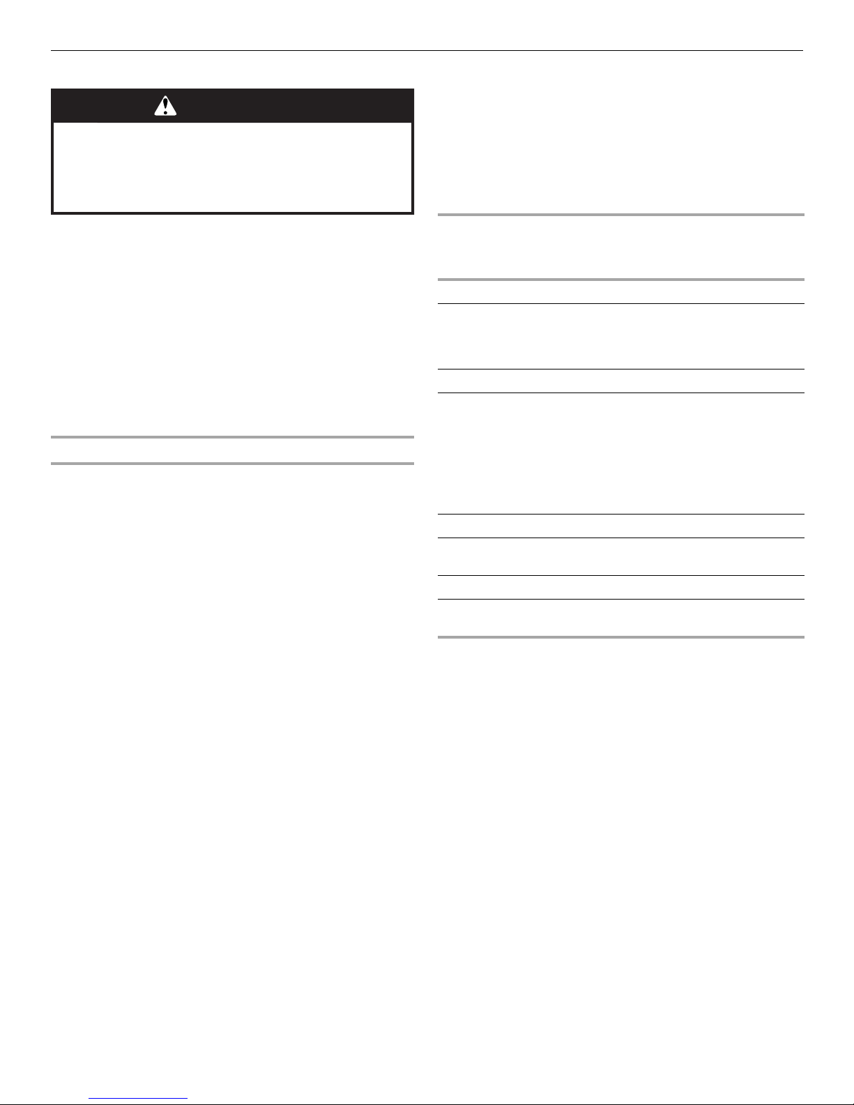
Manually Lighting the Rotisser ie Bur ner
1. Open the hood completely. Do not light burners with the hood
closed.
2. Do not lean over the grill.
3. Remove the manual lighting extension (see following
illustration) and attach a match to the split ring.
4. Strike the match to light it.
5. Gently hold the lit match close to the rotisserie burner.
A.Lighting extension
B.Rotisserie burner
6. Push in and turn the control knob to IGNITE/ON. Hold this
knob in for 10 seconds after the burner is lit. You will hear the
“snapping” sound of the spark until after the knob is released.
Using Y our Rotisserie Burner
A Rotisserie kit can be purchased as an accessory for the grill.
See “Accessories” in the “Assistance” section.
To avoid damage to the warming rack, remove from grill when
using the rotisserie burner.
IMPORTANT: Do not use the main burners when the rotisserie
burner is in use.
Lighting the Rotisse rie Burner
1. Open the hood completely. Do not light burners with the hood
closed.
2. Do not lean over the grill.
IMPORTANT: If the rotisserie burner does not light
immediately, turn the rotisserie burner control knob to OFF
and wait 5 minutes before relighting.
7. Remove the match and repl ac e the ma nu al li ghting extension
inside the cabinet door.
21
Rotisserie Cooking Tips
WARNING
Food Poisoning Hazard
Do not let food sit for more than one hour before or
after cooking.
Doing so can result in food poisoning or sickness.
Rotisserie cooking rotates food in front of the rotisserie burner,
creating an intense heat for searing the outside and sealing in
natural juices.
The rotisserie burner reaches cooking temperatures in about
1 minute. It is not necessary to preheat when using the rotisserie.
■ Select tender meat and poultry.
■ Allow at least 1" (2.5 cm) space between rotiss eri e bu rner a nd
the food.
■ To make cleanup easier, place a pan under the food to catch
drippings.
■ Add barbecue sa uce or gl aze only during t he last 1 0 minutes of
cooking to keep sauce from burning.
Trussing Poultry for the Rotisserie
1. Load the spit rod by sliding one of the forks on the rod, with
the prongs facing inward. Tighten the screw to keep it from
slipping.
2. Push the rod through the center of the bird.
3. Cut 24" (61.0 cm) of butcher’s string and center it under the
bird, breast side up.
4. Wrap each end of the string around the wings; catch each
wing tip. Bring the string tightly together at the top of the
breast and knot. It is not necessary to cut off the extra string.
5. Cut another 20" (50.8 cm) of stri ng and lay i t under the ba ck of
the bird. Wrap it around the tail then around the spit rod,
cinching tightly.
6. Cross the legs on top of sp it rod; tie string a rou nd the c r oss ed
legs.
7. Connect the twine holding the legs, to the string holding the
wings, and knot. Cut off any bits of hanging string.
8. Slide on the second fork pushi ng th e ti nes in to th e dru ms tic ks .
9. Center the food and forks on the rod and tighten the thumb-
screws. The bird s hould be firmly in pl ace on th e rotisser ie spit
rod.
ROTISSERIE CHART
Use a portable meat thermometer to check internal doneness of
the food.
Turn off rotisserie burner when meat thermometer reads 5°F/3°C
lower than desired internal temperature. Continue rotating, hood
closed, for 10 minutes before carving.
Timing is af fected by weathe r conditi ons such a s wind and out side
temperature.
Food Weight Internal
Doneness or
Temperature
(°F/°C)
Beef
Roasts
Rib Eye
Sirloin Tip
Rib, boneless
Poultry
Chicken
Turkey, whole
Lamb
Boneless leg 4-7 lbs
Pork
Loin roast,
boneless
4-6 lbs
(1.5-2.2 kg)
3-6 lbs
(1.1-2.2 kg)
7-10 lbs
(2.6-3.7 kg)
(1.5-2.6 kg)
4-6 lbs
(1.5-2.2 kg)
Medium-rare
(145°F/ 63°C)
Medium
(160°F/71°C)
Breast
(170°F/ 77°C)
Thigh
(180°F/82°C)
Breast
(170°F/77°C)
Thigh
(180°F/82°C)
Medium
(160°F/71°C)
Medium
(160°F/71°C)
Approximate
Grilling Time
(min/lb)
15-20
20-25
25-30
25-30
11-20
11-20
20-25
20-23
22

TIPS FOR OUTDOOR GRILLING
WARNING
Food Poisoning Hazard
Do not let food sit for more than one hour before or
after cooking.
Doing so can result in food poisoning or sickness.
Before Grilling
■ Thaw food items before grilling.
■ Preheat grill on high (use all grill burners) 10 minutes. The
hood must be closed during preheating. There is no need to
use the back rotisserie burner for preheating. Preheating
provides the high heat needed to brown and seal the juices.
■ Shorten the preheat time when grilling high-fat cuts of meat or
poultry, such as chicken thighs. This will help reduce
flare-ups.
■ Lightly oil the grill gra tes or th e fo od w he n c ook in g lo w -fat c uts
of meat, fish or poultry, such as lean hamburger patties,
shrimp or skin less chicken breasts.
■ Using too much oil can cause gray ash to deposit on food.
■ Trim excess fat from meats prior to cooking to reduce
flare-ups.
■ Make vertical cuts at 2 " (5 cm) in terv al s around the fat edge of
meat to avoid curling.
■ Add seasoning or salt only after the cooking is finished.
Indirect Heat
For best results, do not select the indirect heat cooking method
when it is windy.
Cooking by indirect heat means the food is placed on the grill
grate above an unheated burner, allowing heat from lighted
burner(s) on either side to cook the food.
If possible, turn on 2 burners. Cook with the hood down. This will
shorten the cooking time.
During Grilling
■ Turn foods only once. Juices are lost when meat is turned
several times.
■ Turn meat just when juices begin to appear on the surface.
■ Avoid puncturing or cutting the meats to test doneness. This
allows juices to escape.
■ It may be necessary to lower the heat setting for foods that
cook a long time or are marinated or basted in a sugary
sauce.
■ If using a high flame, add barbecue sauce only during the last
10 minutes of cooking to avoid burning the sauce.
■ The degree of doneness is influenced by the type of meat, cut
of meat (size, shape and thickness), heat setting selected,
and length of time on the grill.
■ Cooking time will be longer with an open grill cover.
Cooking Methods
Direct Heat
Cooking by direct heat means the food is placed on grill grates
directly above lighted burners. Hood position can be up or down.
If hood is in the up position, total cooking times may be longer.
Direct heat sears th e fo od . Searing is a proces s that seals natural
juices in food by cooking with intense heat for a short period of
time. While juices stay inside, the outside is browned with a
flavorful grilled coating.
23

■ Knobs have High, Medium and Low settings for flame
adjustment.
■ Heat settings indicated are approximate.
■ Grilling times are affected by weather conditions.
Grilling Chart
■ When 2 temperatures are listed, for example: Medium to
Medium-Low, start with the first and adjust based on cooking
progress.
■ Cooking times may vary from chart times depending on the
type of fuel, Natural or LP gas.
FOOD COOKING METHOD/
BURNER SETTING
Beef
Hamburgers ½" (1.3 cm) to
¾" (1.9 cm) thick
Roasts
Rib Eye, Sirloin
Steaks, 1" (2.5 cm)
Porterhouse, Rib, T-bone,
DIRECT
Medium
INDIRECT
Medium/OFF/Medium
DIRECT
Medium
Top Loin, Sirloin
Steaks, 1½" (3.8 cm)
Porterhouse, Rib, T-bone,
DIRECT
Medium
Top Loin, Sirloin
Top Round or Shoulder/
Chuck (London Broil)
DIRECT
Medium
1½" (3.8 cm) thick
Flank, ½" (1.3 cm) thick
DIRECT
Medium
Pork
Chops,
1" (2.5 cm)
1½" (3.8 cm) thick
Ribs
2½-4 lbs (0.9-1.5 kg)
Roast, boneless tenderloin,
1 lb (0.37 kg)
Ham half,
8-10 lbs (3-3.7 kg)
DIRECT
Medium to Med-Low
INDIRECT
Med/OFF/Med
DIRECT
Medium
INDIRECT
Med/OFF/Med
INTERNAL TEMP. TIME
(total minutes)
Medium (160°F/71°C)
Med-Rare (145°F/63°C)
to Medium (160°F/71°C)
Med-Rare (145°F/63°C)
10-15
32-40 per lb
(15-18 per kg)
11-16
to Medium (160°F/71°C)
Med-Rare (145°F/63°C)
18-25
to Medium (160°F/71°C)
Med-Rare (145°F/63°C)
22-29
to Medium (160°F/71°C)
Med-Rare (145°F/63°C)
Medium (160°F/71°C)
11-16
12-22
30-40
Medium (160°F/71°C)
Medium (160°F/71°C)
Reheat (140°F/60°C)
40-60
18-22
2-2½ hours
SPECIAL INSTRUCTIONS
Grill, turning once.
Tent with foil first 45-60 minutes
of cooking time.
Rotate steaks ¼ turn to create
criss-cross grill marks.
Grill, turning occasionally.
During last few minutes brush
with barbecue sauce if desired.
When done, wrap in foil.
Turn during co oking to brown on
all sides.
Wrap entire ham in foil and put
on grill without pan or drip pan.
Ham steak precooked,
½" (1.3 cm) thick
DIRECT
Preheat Medium
Grill Medium
Hot Dogs
DIRECT
Medium
Chicken
Breast, boneless
DIRECT
Medium
Pieces, 2-3 lbs (0.75-
1.1 kg)
DIRECT
Med-Low to Medium
Lamb
Chops and Steaks,
Loin, Rib, Sirloin
1" (2.5 cm) thick
DIRECT
Medium
1½" (3.8 cm) thick
DIRECT
Medium
24
Reheat (145°F/63°C)
Reheat (145°F/63°C)
170°F/77°C
Breast 170°F/77°C
Thigh 180°F/82°C
Med-rare (145°F/63°C)
to Medium (160°F/71°C)
Med-rare (145°F/63°C)
to Medium (160°F/71°C)
7-10
5-10
Slit skin if desired.
15-22 For even cooking, poun d breas t
to ¾" (2.0 cm) thick.
Start bone side down.
10-20
16-20

FOOD COOKING METHOD/
BURNER SETTING
Fish and Seafood
Fillets, Steaks, Chunks
Halibut, Salmon,
DIRECT
Medium
Swordfish, 8 oz (0.25 kg)
Whole, Catfish, Rainbow
Trout, 8-11 oz (0.25-
DIRECT
High
0.34 kg)
Shellfish, Scallops, Shrimp
DIRECT
Medium
Turkey
INTERNAL TEMP. TIME
(total minutes)
4-6 per
½" (1.3 cm)
thickness of fish
5-7 per side
4-8
SPECIAL INSTRUCTIONS
Grill, turning once. Brush grill
with oil to keep fish from
sticking. Remove when inside is
opaque and flaky with skin
easily removed.
Whole breast (bone-in)
Half breast (bone-in)
Whole,
7-12 lbs (2.6-5.4 kg)
Fresh Vegetables
Corn on the cob
Eggplant
Onion,
½" (1.3 cm) thick
Potatoes,
Sweet, whole
Baking, whole
Peppers,
Roasted
Squash,
Summer, Zucchini
Garlic
Roasted
INDIRECT
HI/OFF/HI
INDIRECT
Medium/OFF/Medium
INDIRECT
HI/OFF/HI
DIRECT
Medium
DIRECT
Medium
DIRECT
Medium
DIRECT
Medium
DIRECT
High
DIRECT
High
DIRECT
Medium
DIRECT
Medium
170°F/77°C
170°F/77°C
Breast 170°F/77°C
Thigh 180°F/82°C
14-18 per lb
(7-8 per kg)
25-30 per lb
(11-14 per kg)
11-16 per lb
(5-7 per kg)
20-25
7-10
8-20
40-70
45-90
15-22
7-10
20-25
Tent with foil until last
30 minutes of cooking time.
Start skin side down.
Less than 11 lbs (5.0 kg)
Soak in cold water 20 minutes.
Do not husk. Shake off excess
water.
Wash and cut into ½" (1.3 cm)
slices or lengthwise. Brush with
olive oil.
Grill, turning once. Brush with
olive oil. Put a skewer through
several slices to hold together.
Individually wrap in heavy-duty
foil. Grill, rotating occasionally.
Wash and place on grill whole.
Char skin all around. Cool in a
paper bag or plastic wrap to
loosen blackened skin. Peel
and remove seeds.
Wash and cut into ½" (1.3 cm)
slices or lengthwise. Brush with
olive oil.
Cut off top, drizzle with olive oil
and wrap in double layer of foil.
25
OUTDOOR GRILL C ARE
A
B
A
B
A
B
A
Replacing the Igniter Battery
If igniters stop sparking, the battery should be replaced.
1. Open cabinet door.
2. Unscrew igniter button cap counterclockwise to remove.
A.“AA” size battery
B.Igniter push button
3. Remove battery from the battery compartment.
4. Replace with a new alkaline “AA” size battery. Install battery
with negative end in first.
5. Screw igniter button cap clockwise into place.
4. Loosen the screw securi ng the lig ht asse mbly to the grill ho od
and pull out the light with glass light cover.
A.Screw
B.Light assembly
Changing the Light Bulb
1. Unplug grill or disconnect power.
2. Make sure the light power sw it ch on the control p an el is in the
OFF position.
3. Use a Phillips screwdriver to loosen the two screws securing
the glass light cover to the grill hood.
A.Screws
B.Hood light cover
NOTE: When removing final screw from the glass light cover,
make sure to hold the cover in place, ensuring it doesn’t fall
and shatter.
5. To remove glass light cover, remove screw and gently pry
downward with a small flat-blade screwdriver at the left edge
of the cover near the screw and pull away from the retainer.
6. Use a flat-blade screwdriv er to remove the two scre ws locking
the bulb into place.
A.Screws
7. Remove bulb from socket.
26
8. Replace bulb with a new 12-volt, 10-watt maximum, halogen
A
bulb, using a tissue or w earing cotton gloves to handle the
bulb. To avoid damaging the bulb, do not touch the bulb with
bare fingers.
When completely cool, grill racks can be removed for thorough
cleaning. Clean them with a mild detergent and warm water.
For baked-on soil, prepare a solution of 1 cup (250 mL) ammonia
to 1 gal. (3.75 L) water. Soak grates for 20 minutes, then rinse
with water and dry completely.
WARMI NG SH ELF
Cleaning Method:
■ Liquid detergent or an all-purpose cleaner.
■ Rinse with clean water and dry with soft, lint-free cloth.
■ For tough spots or baked-on grease, use a commercial
degreaser designed for stainless steel.
IMPORTANT: Make sure gas supply is off and all control knobs
are in the Off position.
A.Bulb
9. Tighten the two screws to lock the bulb into place.
10. Replace glass light cover onto light assembly. Secure light
assembly into the grill hood with the removed in Step 4.
Secure glass light cover onto grill hood with two screws
removed in Step 3.
11. Plug in grill or reconnect power.
General Cleaning
IMPORTANT: Before cleaning, make sure all controls are off and
the grill is cool. Always follow label instructions on cleaning
products.
For routine cleaning, wash with soap and water using a soft cloth
or sponge. Rinse with clean water and dry at once with a soft, lintfree cloth to avoid spots and streaks.
Do not use steel wool to clean the grill, as it will scratch the
surface.
To avoid weather damage to finish, use vinyl grill cover.
ST AINLESS STEEL
IMPORTANT: T o a void d amag e to st ain less steel surfac es, do not
use soap-filled scouring pads, abrasive cleaners, cooktop
polishing creme, ste e l wool, gritty washc loths or paper towels.
Cleaners should not contain chlorine. Damage may occur.
Food spills shou ld be c le ane d as so on as entire grill is co ol. Spills
may cause permanent discoloration.
Cleaning Method:
■ Rub in direction of grain to avoid scratching or damaging the
surface.
■ Stainless steel cleaner
■ Liquid detergent or all-purpose cleaner:
■ Rinse with clean water and dry with soft, lint-free cloth.
■ Vinegar to remove hard water spots.
■ Glass cleaner to remove fingerprints.
EXTERIOR
The quality of this material resists most stains and pitting,
providing that the surface is kept clean, polished and covered.
■ Apply stainless s teel po lish to al l non-cooki ng areas be fore first
use. Reapply afte r each cl eanin g to avoi d perma nent da mage
to surface.
■ Cleaning should al ways b e followed b y rinsin g with cl ean warm
water.
■ Wipe the surface completely dry with a soft cloth.
■ For tough spots or baked-on grease, use a commercial
degreaser designed for stainless steel.
INTERIOR
Discoloration of stainless steel on these parts is to be expected,
due to intense heat from the burners. Always rub in the direction
of the grain. Cleaning should always be followed by rinsing with
clean, warm water.
Cleaning Method:
■ Liquid detergent or all-purpose cleaner.
■ Rinse with clean water and dry completely with a soft, lint-free
cloth.
■ A heavy-duty scrub sponge can be used with mild cleaning
products.
■ For small, diffi cult-to-cl ean area s, use a c ommerci al degre aser
designed for stainless steel.
BURNERS
Cleaning Method:
■ Clean the exterior of the burner with a wire brush.
■ Clear any clogged burner ports with a straightened paper clip.
■ Do not use a toothpick as it may break off and clog the port.
GRILL GRATES
IMPORTANT: To avoid damage to grill grates, do not use a steel
or fiber scraper. Immediately after you are finished cooking,
loosen food soil with a brass bristle brush. Turn all burners to HI
for 10-15 minutes with the hood closed to burn off food soil. Turn
off all burners, raise the hood and let grates cool. Use the brass
bristle brush to remove ash from the grill grate s.
27
■ Check and clean burner/venturi tubes.
A
A
1. Remove grill grates and flame tamers.
2. Remove 1 screw and clip that hold the burner in place.
Remove gas burner from the grill.
A.Clip
3. Use a flashlight to inspect into the burner through the
burner inlet to ensure there is no blockage. I f any
obstruction is se en, use a met al coat hange r that has be en
straightened to clear them.
4. After inspecting the inside of burner for blockage,
reassemble burner by sliding the middle tube of the gas
burner over the gas orifice.
ROTISSIERE BURNER
Cleaning Method:
1. Light the rotisserie burner. See the “Using Your Rotisserie
Burner” section.
2. Close the grill hood.
3. Leave the burner on high for approximately 30 minutes.
4. Turn knob to OFF and let cool completely.
5. Brush off ash particles from the rotisserie burner.
DRIP TRAY
IMPORTANT: The drip tray should only be removed when grill is
completely cool.
The full-width drip tray collects grease and food particles that fall
through the grill. Clean often to avoid grease buildup.
Cleaning Method:
■ Remove tray and set on a flat surface.
■ Wipe excess grease with paper towels.
■ Mild detergent and warm water. Rinse and dry thoroughly.
■ Replace tray.
KNOBS AND FLANGE ARE A AROUND KN OBS
IMPORTANT: To avoid damage to knobs or flange area around
knobs, do not use steel wool, abrasive cleaners, or oven cleaner.
Do not soak knobs.
Cleaning Method:
■ Mild detergent, a soft cloth and warm water.
■ Rinse and dry.
A.Burner/orifice connection
5. Reattach gas burner using the screw and the clip.
SEARING SIDE BURNER
Cleaning Method:
■ Clean the exterior of the sear burner with a wire brush.
CONTROL PANEL GRAPHICS
IMPORTANT: To avoid damage to control panel graphics, do not
use steel wool, abrasive cleaners or oven cleaner.
Do not spray cleaner directly onto panel.
Cleaning Method:
■ Clean around the burner labels gently; scrubbing may remove
printing.
■ Mild detergent, soft cloth and warm water.
■ Rinse and dry.
28

TROUBLESHOOTING
Grill will not ligh t
■ Is the 20 lb LP gas fuel tank valve turned off?
Turn the 20 lb LP gas fuel tank on.
■ Is the grill properly connected to the gas supply?
Contact a trained repair specialist or see Installation
Instructions.
■ Is there gas in the 20 lb LP gas fuel tank?
Check the gas level.
■ Is the igniter working?
Check that the igniter battery is properly installed or check to
see if the battery needs to be replaced. See the “Replacing
the Igniter Battery” section.
Check to see if the grill will match-light. See “Manually
Lighting the Main Grill” in the “Outdoor Grill Use” section.
Check for loose wire connections to the igniter or electrodes.
Check to see if debris is blocking the electrodes.
If a spark occurs anywhere but the igniter tip, replace the
igniter.
Burner flame will not stay lit
■ Is the gas supply fully turned on?
Check that the 20 lb LP gas fuel tank valve is fully open.
■ Is the gas supply in the 20 lb LP fuel gas tank low?
Check the gas level.
■ Is the burner properly installed and in good condition?
Check that the burner is installed properly. Check for defects
in the burner.
Flame is noisy, low or erratic
■ Is the gas supply fully turned on?
Check that the 20 lb LP gas fuel tank valve is fully open.
■ Is the gas supply in the 20 lb LP fuel gas tank low?
Check the gas level.
■ Does only one burner appear low?
Check and clean the burner ports if clogged or dirty. See
“General Cleaning” section.
■ Is the gas supply hose bent or kinked?
Straighten the gas supply hose.
■ Is the flame noisy or lifting away from the burner?
Burner may be getting too much air. Check the air shutter
adjustment, see “Check an d Adjust Burne rs” section.
■ Is the burner flame mostly yellow or orange?
Grill may be in an area that is too windy, or not receiving
enough air. Check the burner air inlets for ob st ruction s. Che ck
the air shutter adjustment, see “Check and Adjust Burners”
section.
Excessive flare-up s
■ Is there excessive fat in the food being grilled?
Keep flame on low or turn one burner off.
Keep the hood up when grilling to avoid excessive flare-ups.
Move food to the warming rack until flames subside.
To avoid damage to the grill, do not spray water on gas
flames.
Low heat
LP Gas:
For outdoor grills using a 20lb LP gas fuel tank, slowly open the
tank valve.
NOTE: If flow limiting device activates, your grill may not light. If
your grill does light, the flames will be low and will not heat
properly.
1. Turn tank valve and all control knobs off and wait 30 seconds.
2. After shutting of f th e t ank, v ery sl owly o pen the tan k val ve and
wait 5 seconds before lighting.
3. Light the burners one at a time. See “Lighting the Main Grill”
section.
Natural Gas:
Gas pressure is affected by size and length of the gas line from
the house to the grill. C ontact a qualified g as technic ian to provi de
the Natural gas supply to the selected grill location in accordance
with the National Fuel Gas Code ANSI Z223.1/NFPA54 - latest
edition, and local codes.
ASSISTANCE
Before calling for assistance, please check “Troubleshooting.” If
you still need help, follow the instructions below.
When calling, please know the purchase date and the complete
model and serial number of your appliance. This information will
help us to better respond to your request.
If you need replacement p a rt s
If you have questions o r nee d to order replacement pa r t s , co nt ac t
Customer Service Center at 1-800-554-5799 or fax to
1-800-598-8829.
Please direct all correspondence to:
Nexgrill Industries, Inc.
5270 Edison Avenue
Chino, CA 91710
Please include a daytime phone number in your correspondence.
Accessories
Natural Gas Conversion Kit
Order Part Number 710-0003
Rotisserie Kit
Order Part Number 790-0007
29
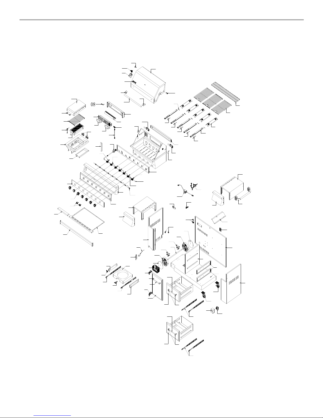
08
03
02
01
95
16
15
94
93
09
06
07
05
11
02
04
96
25
21
24
23
85
84
84
82
26
22
20
19
18
17
12
87
88
89
90
86
12
92
91
83
10
14
13
30
80
81
36
79
78
77
41
74
2
8
29
34
3
7
35
33
32
31
73
27
70
45
43
44
56
55
47
38
39
46
7
2
40
45
42
46
71
75
76
69
65
62
60
68
66
67
53
50
48
49
44
51
52
51
50
49
5
7
61
60
59
5
8
53
54
50
51
54
6
3
64
REPLA CEMENT PARTS
30
 Loading...