

Page 1
Downdraft
Ducting
Guide
T
HE
S
IGN OF A
G
REAT
C
OOK
®
®
Downdraft
Ducting
Guide
Page 2
Important Information
Dealer
Installer
Model and Serial Numbers
Equivalent Length
Fittings Required
Questions
Page 3
When considering the location for a Jenn-Air product, environmental influences that can affect ventilation performance must be considered.
Make-Up Air - The air that is exhausted by the unit
must be replaced. If a room or house is too “tight”,
the unit may not vent properly. If a house or room is
too tight, it will be necessary to introduce more air
into the environment. Some air conditioning and
heating units allow for make-up air.
Air Movement - Any other air movement devices
such as, ceiling fans, air conditioner registers, etc.
can create air currents which interfere with downdraft ventilation.
Adjacent Cabinets - Cabinets that are closer than
the minimum distance allowed can create dead air
pockets that impair performance. For maximum
performance, the recommended distance to adjacent
cabinets or walls is 6”. However, the minimum
clearance can be from 2 inches for cooktops to 1
inch for ranges. Please refer to the installation
instructions for the particular product.
Jenn-Air downdraft ranges and cooktops will adapt
to various installation locations. The blower assembly is capable of duct runs up to 60 equivalent feet.
When planning a particular installation, please refer
to this guide to ensure that all of the ducting needs
will be met. Always refer to the product and ducting installation instructions included with the JennAir product.
Jenn-Air downdraft ventilation systems are
designed to move air at a high rate of speed. High
speed air flow will ensure the exhausting of smoke
and fumes and will hold grease and moisture in suspension until exiting the home.
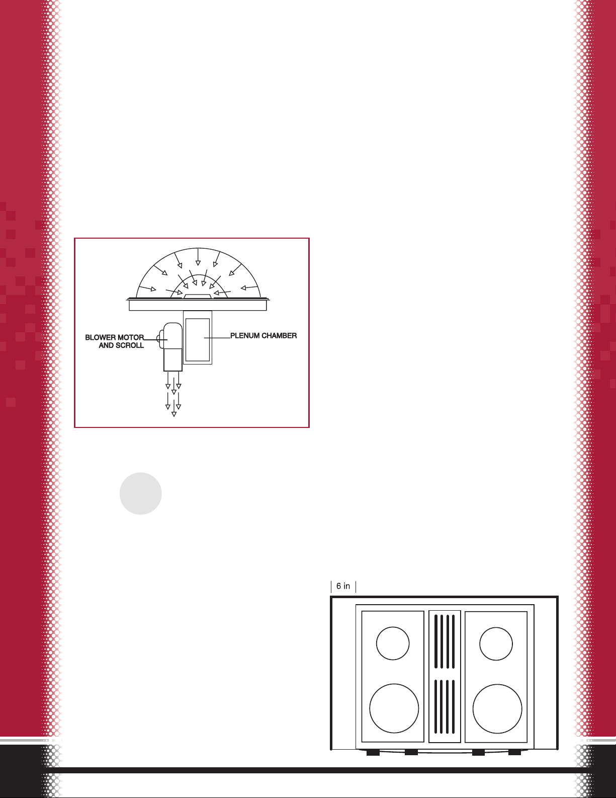
The downdraft cooking system operates on the
principle of localized or “proximity” ventilation.
This system creates a high velocity exhaust air pattern near the cooking surface. The air movement is
created by a blower motor and squirrel cage fan
blade encapsulated by a blower scroll. This scroll is
aligned with a plenum chamber. On cooktops, the
scroll is attached directly to the plenum chamber.
On ranges it mounts remotely under the range.
Since this system differs from the familiar forced-air
heating and air conditioning system you may have
in your home that uses low velocity air flow, the
Jenn-Air system will require different duct work
design techniques.
This guide will take you step-by-step through the
planning process and will assist you in determining
the types of materials needed to properly install a
Jenn-Air product.
The goal of the system is to maintain the proper
amount of airflow to efficiently pull smoke and
other cooking fumes to the outside without pulling
excessive air across the cooking surface. Too little air
movement will result in a smoke filled kitchen
while too much air movement will result in prolonged cooking times due to cooled off food.
The equipment design is flexible enough that the
ducting can be done simply with up to three turns
(elbows) and not rely on fancy sheet-metal work.
Proximity Ventilation Cooktop Example
Introduction
1
STEP
Environment
Page 4

Downdraft Ranges - Blower mounts to floor and has a flexible
connection to the range.
Rear Duct (Inside Wall) to the roof
Through the wall in back of the grillrange directly to the outside
Down through the floorF, along the
floor joists and through the foundation
or an outside wall
5” Dia. Duct
5” Dia. Duct
5”
Wall
Cap
6” Wall
Cap
The ability to rotate the blower 90 degrees provides
great flexibility to most installation types. On
ranges, the blower is positioned on the floor.
On cooktops, it is positioned under the cooking surface. The following graphics depict common installation types.
Cooktops - Blower mounted to cooktop (Expression
®
Collection examples shown)
5” to 6”
Transition
5” to
3-1/4” x 10”
Transition
Elbow
Jenn-Air Roof Rack
Up Inside Wall to
Roof or Overhang
Inside Wall Cabinet
Maximum of 54’
of 3-1/4” x 10”
Duct
5” to 3-1/4” x
10” Elbow
Directly to Outside
Outside Wall Cabinet
Thru Cabinet Toe Space
Peninsula
(no wall behind)
3-1/4” x 10”
Transition
Elbow
Between Floor Joist
Peninsula or island
6” Elbow
Maximum
of 51-1/2’
of 6" Duct
Jenn-Air 6”
Wall Cap
5” to 6”
Transition
Notes:
A.For venting up to the equivalent of 60’, use standard aluminum or steel
ducting and elbows.
B. IMPORTANT: See installation instructions shipped with product before
selecting island cabinetry, making cutouts or beginning installation. For
best performance, it is suggested that no more than three 90 degree elbows be used with 6" or 3-
1
/4" x 10"
duct. Each foot of metal flex duct counts as two feet of rigid metal duct. Each flex elbow counts as two
metal elbows. For longer duct runs of 31' to 60', the restricter ring on the blower inlet housing must be
removed. 6" round or 3-1/4" x 10" duct must be used for ducting beyond 10' (up to 60'). Failure to follow
ducting recommendations or use recommended ducting accessories may result in substandard performance.
C. Count each 90 degree elbow as 5' of duct.
D.When venting electric ranges or cooktops, 5" diameter round duct may be used to vent straight out the
back of appliance and directly through the wall for runs of 10' or less.
E. When venting dual-fuel ranges and gas cooktops, 5" diameter round duct must be used for runs of 10'
or less.
F. When installing through a slab, it is essential that the system be properly calculated, designed and
installed before the house is built, when the slab is poured.
Duct Length Recommendations
A
(Maximum)
B
5” Diameter
C
All Electric
D
All Gas
E
10’
10’
60’
60’
6” Diameter
or 3-1/4” x 10”
C
Installation Types
2
STEP
Page 5

DO NOT EXCEED
60 EQUIVALENT FEET
Example
5˝ to 6˝ Transition 1 ft
2 ft of 6˝ Round + 2 ft
6˝ Elbow + 5 ft
4 ft of 6˝ Round + 4 ft
6˝ Elbow + 5 ft
6 ft of 6˝ Round + 6 ft
Jenn-Air Wall Cap + 0 ft
23
EQUIVALENT
FEET
5˝, 6˝ or 3 1/4˝ x 10˝ 90 Degree Elbow
6˝ Diameter, 5˝ Diameter or
3
1
/4˝ x 10˝ Straight Duct
5 Feet
(5˝) 580357
(6˝) 580356
(3
1
/4˝x 10˝) 580359
(5˝) 580362
(6˝) 580361
A456
701944
701944
(no MCS #)
701945
701945
580360
(3
1
/4˝x 10˝) A403
(5˝) A405
Roof Cap 701943
708786
21/2Feet
1 Feet
5 Feet
9 Feet
6 Feet
1 Feet
4
1
/2Feet
12 Feet
0 Feet
2 Feet
1 Foot per Foot
(Metal Flex= 2
Feet per Foot)
Duct Fitting
Equivalent
Length
No. of
Fittings
Total Equivalent
Lengh-Fitting
Use Table Below to Calculate Total Systems
5˝ or 6˝ 45 Degree Elbow
5˝, 6˝ Transition
6˝ to 3
1
/4˝ x 10˝ Transition Elbow
6˝ to 3
1
/4˝ x 10˝ Transition Elbow
5˝ to 3 1/4˝ x 10˝ Transition Elbow
6˝ to 3 1/4˝ x 10˝ Transition
6˝ to 3
1
/4˝ x 10˝ Transition
3
1
/4˝ x 10˝ Flat Elbow
Jenn-Air Wall or Roof Jack
Jenn-Air Thermal Break
System Equivalent Length:
Equivalent Length Calculation Table
Since fittings such as elbows and transitions affect
air flow through the ducting, they must be accounted for in calculating a duct run. This is done by utilizing a formula that deducts an equivalent length
from the duct run. The following table depicts these
equivalent lengths and may be used as a worksheet
to determine your equivalent length deductions.
3
STEP
Calculating the Duct Length
(6˝) A406
Air Flow
in this Direction
Not Recommended
Air Flow
Air Flow in
this Direction
Only!
Air Flow
Air Flow
Air Flow
5˝ to 6˝ Transition
2´ of 6˝ Round
6˝ Elbow
4´ of 6˝ Round
6˝ Elbow
16´ of 6˝ Round
6˝ Wall Cap
Page 6

Sketching Area
Recommended Materials Include:
■ 3
1
/4in. X 10 in., ALUMINUM\STEEL
(For runs greater than 10 ft. )
■ 6 in. ROUND, ALUMINUM\STEEL
(For runs greater than 10 ft.)
■ 5 in. ROUND, ALUMINUM\STEEL
(For runs under 10 ft.)
Note: 5 in. MUST be used on Gas or Dual-Fuel
Ranges with runs less than 10 ft.
■ 6 in. PVC (Limited to under Concrete Slab. Subject
to Local Codes!)
Note: PVC Elbows count as 10 equivalent feet.
Non-Recommended Materials:
■ Metal Flex Duct (May be used for short runs only)
Note: If Metal Flex is used, multiply equivalent feet
by 2.
■ Vinyl Flex Duct (NEVER!)
■ Any material with less than 5” diameter (NEVER!)
e.g. Dryer Ducting
4
STEP
Use Recommended Ducting Material
3 1/4 in. x 10 in.
5 or 6 in. Round
P.V.C.
Metal Flex
Page 7

We hope this planner has assisted you in your planning for your new Jenn-Air Downdraft product.
Each installation is unique and requires insight and
careful planning. For further product information,
contact your Jenn-Air Dealer or call us at 1-800-6881100 or in Canada, 1-800-688-2002.
Thank You
DO
■ Use recommended wall caps and ducting material
■ Tape and seal all seams and connections
■ Use only professional elbows, fittings and crimps on ducting
■ Duct system to the outdoors
■ Maintain 12 inches from the bottom of the wall cap to the ground
■ Understand environmental influences on air movement
■ Calculate equivalent feet
■ Refer to installation instructions packed with the product
DON’T
■ Cause any restrictions
One of the most common and severe duct restrictions is caused by putting two elbows or fittings next to each other. Frequently, this
configuration is an attempt to get past a floor joist or other obstacle. Elbows and fittings cause turbulence in the air stream. This turbulence carries down the ducting for a considerable distance before it smoothes out again. Putting elbows or fittings together can create a
higher than desired resistance to the air movement.
To prevent this, it is required that a straight duct run be placed between the fittings. As a rule of thumb, this straight section should be at
least two and one half times the diameter of the duct.
Example
: For 6” diameter ducting the straight section should be at least 15 inch-
es ( 2
1
/2x 6” ).
■ Use non-recommended ducting materials
Another commonly found source of poor performance is the use of inadequate ducting material. Their size and configuration effect the
air movement within them. Choose the ducting material carefully and use only those that are Jenn-Air
®
recommended and comply with
Federal and Local building codes.
■ Use screws to attach ducting together
The ventilation system is designed to hold grease and smoke in suspension until it reaches the outdoors where it will condense. If the
duct has any open holes or seams in it, the suspended grease may condense in an undesirable location.
■ Reduce the size of the duct
While the mixing of ducting material is acceptable, you should NEVER reduce the duct size down. If 6” material is used, a reduction to 5”
will create a restriction in the air flow that cannot be overcome. The mixing of 3
1
/4” x 10” with 6” material is acceptable and will not hin-
der performance.
■ Use too many elbows or fittings
The number of elbows should be limited to three per duct run. Due to the restriction each elbow or fitting creates, performance will be
sacrificed if more than three are used.
■ Use a common duct for more than one downdraft
If installing more than one downdraft, each blower assembly will require its own dedicated duct run. If two systems are sharing a common run, some performance situations may occur. Smoke and odor will come out of the unit not operating and poor ventilation performance if both units are operated at the same time. Common duct runs NEVER should be used.
5
STEP
Do’s and Don’ts of Ducting
Page 8

403 West Fourth Street North
Newton, Iowa 50208
Specifications subject to change without notice.
© 1998 Maytag AppliancesPart No. 16009426
T
HESIGN OF AGREATCOOK
®
 Loading...